EP2184652B1 - Spiralfeder mit Endkurvenerhöhung aus mikro-bearbeitbarem Material - Google Patents
Spiralfeder mit Endkurvenerhöhung aus mikro-bearbeitbarem Material Download PDFInfo
- Publication number
- EP2184652B1 EP2184652B1 EP09173722A EP09173722A EP2184652B1 EP 2184652 B1 EP2184652 B1 EP 2184652B1 EP 09173722 A EP09173722 A EP 09173722A EP 09173722 A EP09173722 A EP 09173722A EP 2184652 B1 EP2184652 B1 EP 2184652B1
- Authority
- EP
- European Patent Office
- Prior art keywords
- balance spring
- main body
- curve
- micro
- mechanical fastener
- Prior art date
- Legal status (The legal status is an assumption and is not a legal conclusion. Google has not performed a legal analysis and makes no representation as to the accuracy of the status listed.)
- Active
Links
Images
Classifications
-
- G—PHYSICS
- G04—HOROLOGY
- G04B—MECHANICALLY-DRIVEN CLOCKS OR WATCHES; MECHANICAL PARTS OF CLOCKS OR WATCHES IN GENERAL; TIME PIECES USING THE POSITION OF THE SUN, MOON OR STARS
- G04B17/00—Mechanisms for stabilising frequency
- G04B17/04—Oscillators acting by spring tension
- G04B17/06—Oscillators with hairsprings, e.g. balance
- G04B17/066—Manufacture of the spiral spring
-
- F—MECHANICAL ENGINEERING; LIGHTING; HEATING; WEAPONS; BLASTING
- F16—ENGINEERING ELEMENTS AND UNITS; GENERAL MEASURES FOR PRODUCING AND MAINTAINING EFFECTIVE FUNCTIONING OF MACHINES OR INSTALLATIONS; THERMAL INSULATION IN GENERAL
- F16F—SPRINGS; SHOCK-ABSORBERS; MEANS FOR DAMPING VIBRATION
- F16F1/00—Springs
- F16F1/02—Springs made of steel or other material having low internal friction; Wound, torsion, leaf, cup, ring or the like springs, the material of the spring not being relevant
- F16F1/04—Wound springs
- F16F1/10—Spiral springs with turns lying substantially in plane surfaces
-
- G—PHYSICS
- G04—HOROLOGY
- G04B—MECHANICALLY-DRIVEN CLOCKS OR WATCHES; MECHANICAL PARTS OF CLOCKS OR WATCHES IN GENERAL; TIME PIECES USING THE POSITION OF THE SUN, MOON OR STARS
- G04B17/00—Mechanisms for stabilising frequency
- G04B17/20—Compensation of mechanisms for stabilising frequency
-
- G—PHYSICS
- G04—HOROLOGY
- G04D—APPARATUS OR TOOLS SPECIALLY DESIGNED FOR MAKING OR MAINTAINING CLOCKS OR WATCHES
- G04D3/00—Watchmakers' or watch-repairers' machines or tools for working materials
- G04D3/0002—Watchmakers' or watch-repairers' machines or tools for working materials for mechanical working other than with a lathe
- G04D3/0035—Watchmakers' or watch-repairers' machines or tools for working materials for mechanical working other than with a lathe for components of the regulating mechanism
- G04D3/0041—Watchmakers' or watch-repairers' machines or tools for working materials for mechanical working other than with a lathe for components of the regulating mechanism for coil-springs
Definitions
- the invention relates to a spiral curve elevation and its manufacturing process and, more particularly, to such a spiral made of a micro-machinable material.
- the regulating member of a timepiece generally comprises an inertia flywheel called a balance wheel and a resonator called a spiral. These pieces are decisive for the running quality of the timepiece. In fact, they regulate the movement's movement, that is, they control its frequency.
- the document FR 2 315 714 discloses an example of manufacture of a metal balance spring whose spiral spring is extended by a terminal curve to verify the Phillips theory.
- the object of the present invention is to overcome all or part of the drawbacks mentioned above by proposing a curve-bearing spiral made of micro-machinable material of simple manufacture and which allows a reduced running gap.
- the invention relates to a spiral with a curve elevation of micro-machinable material comprising a spiral spring mounted in one piece and coaxially with a ferrule, a terminal curve and an elevating device between the coil external of said spiral spring and said end curve to improve the development concentricity of said hairspring characterized in that the elevating device comprises a mechanical fastener comprising a main body on which resiliently mounted pinch means for connecting and locking respectively the ends of said outer turn and said end curve against the main body.
- a simple multi-plane assembly is made almost insensitive to magnetism and temperature change which no longer requires the complex developmental steps currently being carried out for the manufacture of such a hairspring from a metal blade.
- the invention relates to a timepiece characterized in that it comprises a spiral curve elevation according to one of the preceding variants.
- a spiral made of a micro-machinable material is produced with a better precision compared to the complex developmental stages currently being carried out for the manufacture of such a spiral from a metal blade. .
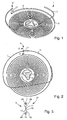
- the hairspring 1 is intended to be mounted in a timepiece in cooperation with a pendulum. It comprises a spiral spring 3, a ferrule 5, a terminal curve 7 and an elevating device 9.
- the spiral spring 3 and the ferrule 5 form a single piece in order to avoid inaccuracies in their interface. which would harm the symmetry of development of the hairspring 1.
- the spiral spring 3 preferably comprises an inner coil 11 comprising a Grossmann type curve.
- a Grossmann type curve makes it possible to compensate for the use of a ferrule 5 by correcting the internal turn 11 with respect to the ideal curve of a perfect spiral of the Archimedes type.
- the shell 5 is generally triangular in shape and is adapted to receive a balance shaft 13.
- the general shape of the axis 13 balance may differ without departing from the scope of the invention.
- the terminal curve 7 is of the Phillips type, that is to say a curve which, during the development of the hairspring 1, makes it possible to keep a center of gravity located on the axis 13.
- the heights of the terminal curve 7 and the spiral spring 3 are identical.
- a silicon-based material can be used. Indeed, it is a micro-machinable material, that is to say a material that can be manufactured with a precision less than one micrometer, for example, by deep reactive ion etching of a crystalline silicon-based plate (also known by the abbreviation "DRIE" from the English terms “Deep Reactive Ion Etching”).
- DRIE deep reactive ion etching of a crystalline silicon-based plate
- silicon is not the only material that has these characteristics.
- Other micro-machinable materials are conceivable, such as, for example, crystalline silica or crystallized alumina.
- the silicon-based material may also be covered with its oxide in order to adapt its expansion but also its thermoelastic coefficient relative to that of the balance to finely adjust the isochronism of the movement of the timepiece, it that is to say, to make minimum its gap of march.
- an elevating device 9 is used to make the outer turn 15 of the hairspring 3 with the end curve 7 situated above said spring spiral.
- the lifting device 9 comprises a mechanical fastener 17 comprising a main body 19 extended on each side by a clamping means 23, 25.
- the Mechanical fastener 17 is also preferably made from a micro-machinable material such as, for example, a silicon-based material.
- the main body 19 of the mechanical fastener 17 is substantially parallelepipedal and comprises a thickness substantially equivalent to the heights of the end curve 7 and the outer turn 15 of the spiral spring 3.
- the clamping means 23, 25 are substantially symmetrical by relative to the main body 19 and each comprise a substantially U-shaped profile intended respectively to attach to the end of the end curve 7 and the end of the outer coil 15 of the spiral spring 3 by at least partial overlap.
- the U-shaped profiles are made over the entire width of the mechanical fastener 17 and cover respectively the entire thickness of the end curve 7 and the outer turn 15 of the spiral spring 3 leaving only one of the faces parallel to the heights not covered.
- the profiles of the clamping means 23, 25 may be different from each other and / or not be uniform over the entire width of the mechanical fastener 17 and / or extend only over a part of said width. It can also be envisaged that at least one of the profiles is not U-shaped but substantially circular, elliptical, square or rectangular, thus allowing the end of the end curve 7 and / or the turn to be completely covered. external 15 of the spiral spring 3.
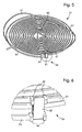
- a spiral with a curve elevation 51 is produced as illustrated in FIGS. Figures 5 to 8 .
- the hairspring 51 is also of the Breguet type and has the same characteristics as the first embodiment except for its lifting device 59. The latter is intended to make the external turn 65 of the hairspring 53 with the terminal curve 57 integral with the hairspring. located above said spiral spring.
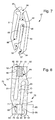
- the elevating device 59 comprises a mechanical fastener 67 comprising a main body 69 on which resiliently clamping means 73, 75 are mounted so as to respectively block the ends 61, 63 of the outer turn 65 and of the end curve 57 against the main body 69.
- the mechanical fastener 67 is also preferably made from a micro-machinable material such as, for example, a silicon-based material.
- the mechanical fastener 67 has a substantially parallelepipedal main body 69 and, preferably, has, like the mechanical fastener 17 of the first embodiment, a central symmetry with respect to the center O of the main body 69.
- nip 73, 75 comprise a first 81 and a second 83 arms respectively attached to a first 71 and a second 77 ends of the main body 69 and are respectively intended to attach to the end 61 of the terminal curve 57 and to the end 63 of the outer turn 65 of the spiral spring 53 by at least partial overlap.
- the arms 81, 83 are substantially parallel to the main body 69.
- the arms 81 and 83 are made elastically movable by forming recesses 88, 90 allowing their movement relative to the main body 69.
- each of the ends 61, 63 is blocked according to its thickness by pushing a contact 82, 86 of one of said arms 81, 83 against a stop 72, 76 of the main body 69.
- the contact 82 of the first arm 81 pushes the end 61 of the end curve 57 against the abutment 72 of the end 77 of the main body 69.
- the contact 86 of the second arm 83 pushes the end 63 of the outer coil 65 the spring-spring 53 against the abutment 76 of the end 71 of the main body 69.
- the fastener 67 makes it possible to pinch each of the ends 61, 63 according to its thickness.
- each contact 72, 76 is resiliently mounted on its end 77, 71 by forming recesses 68, 92 allowing their movement relative to the rest of the main body 69.
- the elevating device 59 also allows each of the ends 61, 63 to be locked also according to its height by pushing a second contact 80, 84 of one of said arms 81, 83 against a second stop 70, 74 of the main body 69.
- each arm 81, 83 has a hook-like lug 85, 87 which supports one of said second contacts 80, 84 located substantially perpendicular to the first contact 82, 86.
- the lugs 85 and 87 are rendered movable elastically by forming recesses 66, 94 allowing their movement relative to their arm 81, 83.
- the contact 80 of the first arm 81 pushes the end 61 of the end curve 57 against the stop 70 of the tip 77 of the main body 69.
- the contact 84 of the second arm 83 pushes the end 63 of the turn external 65 of the spiral spring 53 against the abutment 74 of the end 71 of the main body 69.
- the fastener 67 can also pinch each of the ends 61, 63 according to its height.
- the profiles of the clamping means 73, 75 may be different from each other and / or not be uniform over the entire width of the mechanical fastener 67 and / or extend only over a part of said width. It can also be envisaged that at least one of the profiles is substantially circular, elliptical, square or rectangular, thus completely covering the end 61 of the end curve 57 and / or the end 63 of the outer turn 65 spiral spring 53.
- the elevating device 59 comprises, on at least one of said ends, bulges 62, 64 making it possible to limit the position of the fastener 67 with respect to the length of said at least one of said ends.
- the beads 62, 64 visible only to Figures 5 to 8 , but perfectly applicable to the first embodiment which is not part of the claimed invention, form a frame of four studs for blocking, respectively, on the one hand, the first arm 81 and the end 77 of the main body 69 according to a certain position with respect to the length of the end curve 57 and, secondly, the second arm 83 and the end 71 of the main body 69 at a certain position relative to the length of the spiral spring 53.
- the elevating devices 9, 59 may also comprise securing means 27 intended to improve the fixing force of the elevating device 9, 59.
- the securing means comprise a layer 29 between the mechanical fastener 17, 67 and the ends of the end curve 7, 57 and the outer turn 15, 65 of the spiral spring 3, 53.
- Such a layer 29 can thus have a adhesive material, a metallic material, an oxide or a melting alloy of the materials used or even a solder.
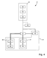
- the method 31 for manufacturing a curve-elevating hairspring 1, 51 according to the invention will now be explained using the figure 4 .
- the method 31 mainly comprises a component manufacturing step 33 and a component assembly step 37.
- the method also comprises a step of mechanically reinforcing said components and a step 41 of reinforcing the assembly.
- the first step 33 is intended to manufacture, during the respective phases 30, 32 and 34, the components of the upward-spiral balance spring 1, 51, that is to say the spiral spring assembly 3, 53-ferrule 5, 55, the end curve 7, 57 and the elevating device 9, 59.
- a wet or dry micro-machining method is used.
- the micromachining can be an anisotropic dry attack of the deep reactive ion etching type of a crystalline silicon-based plate (also known as "Deep Reactive Ion Etching").
- the phases 30, 32 and 34 consist initially of coating the plate with a protective mask, for example by means of a photolithography process of a photoresist.
- a protective mask for example by means of a photolithography process of a photoresist.
- the plate is subjected to the anisotropic attack, only the parts of the unprotected plate being etched.
- the protective mask is removed. It is therefore clear that the protective mask directly determines the final shape of the etched components.
- the spiral curve elevation 1, 51 according to the dimensions of movements or calibres existing.
- the movements or calibres can always be made by swapping only the curve-up spiral.
- the second step 37 is intended to assemble the components etched in step 33, that is to say the spiral spring assembly 3, 53 - ferrule 5, 55, the terminal curve 7, 57 and the device of FIG. 9, 59.
- each necessary component is detached from the engraved plate, for example by breaking bridges of material left between each component and its plate.
- the three flat components are assembled to make the hairspring 1 from three parts.
- the end of the outer turn 15, 65 of the spiral spring 3, 53 is thus engaged in one of the clamping means 25, 75 of the mechanical fastener 17, 67 and that of the end curve 7, 57 in the other clamping means 23, 73.
- the hairspring 1 comprises an overall height equal to twice the thickness of the engraved plate, representing the end curve 7 and the hairspring assembly 3 - ferrule 5, and the length of the mechanical fastener 17 which does not cover the latter.
- the mechanical fastener 17 is preferably etched in the plate according to the pattern of the figure 3 .
- the hairspring 51 has an overall height equal to the height of the mechanical fastener 67.
- the method 31 may also include a step 35 for reinforcing the etched components.
- a step 35 for reinforcing the etched components may consist in producing a plasma oxidation capable of creating on the surface of the dioxide of silicon.
- the reinforcing step 35 is carried out between the etching step 33 and the assembly step 37, which makes it possible to oxidize the entire etched plate, that is to say all the components at the same time.
- step 35 can also be performed after phases 30 and / or 32 and / or 34.
- the method 31 may also include a step 41 for reinforcing the assembly of the etched components.
- a step 41 for reinforcing the assembly of the etched components there are three distinct embodiments whose processes are represented using double, triple or quadruple lines.
- step 41 of reinforcing may consist in depositing, during a phase 43, a layer 29 inside the clamping means 23, 73 and / or 25, 75 in order to allow the driving of the mechanical fastener 17, 67 on the ends of the end curve 7, 57 and the outer coil 15, 65 of the spiral spring 3, 53.
- a layer 29 could consist of a metal layer obtained, for example, by physical vapor deposition.
- the absence of silicon plastic field may require the use of a layer 29 capable of deforming to prevent the breaking of the clamping means 23, 73, 25, 75 because the driving force necessary for proper operation the spiral 1, 51 can generate a stress greater than the limit of the elastic zone of said silicon.
- the layers 29 may also be deposited not inside the clamping means 23, 73, 25, 75 but on the ends of the terminal curve 7, 57 and the outer coil 15, 65 of the spring -spiral 3, 53.
- the layers 29 must be, in the first embodiment, deposited before the assembly step 37.
- the filing of phase 43 may also consist of a layer 29 of solder. The brazing could then be carried out either during the assembly step 37 or after.
- step 41 of strengthening the assembly may consist in depositing, during a process 45, an adhesive layer 29 between the clamping means 23, 73 and / or 25, 75 and the terminal curve 7, 57 and of the outer coil 15, 65 of the spiral spring 3, 53 to improve the fixing force of the elevating device 9, 59.
- a first phase 40 may consist in depositing an adhesive material at the interface of the assembled components then, preferentially, in a second phase 42 to heat the assembly in order to activate said adhesive material.
- a layer 29 could then consist, for example, in a layer of polymer adhesive.
- the deposition phase 40 may also be carried out before the assembly step 37 if the adhesive material in the non-activated state is not sufficiently viscous.
- the deposit could then be made inside the clamping means 23, 73, 25, 75 and / or on the ends of the end curve 7, 57 and the outer turn 15, 65 of the spiral spring 3, 53 before the assembly step 37 and, preferably, heated, after the assembly step 37, during the phase 42. It is therefore understood, in this example of the second embodiment, that the layers 29 allow, thanks to their provide adhesion, firmly hold the assembly in place.
- step 41 of reinforcing the assembly may consist in forming, during a process 47, a bonding layer 29 between the gripping means 23, 73 and / or 25, 75 and the terminal curve 7, 57 and spiral spring 3, 53 to improve the fastening force of the lifting device 9, 59.
- a first phase 44 may consist in oxidizing, for example by plasma etching, the surface of the spiral 1, 51 based on silicon in order to form a silicon dioxide gangue capable of improving the joining of its assembled components and then, preferably, in a second phase 46 to heat the assembly to complete said joining.
- the oxidation phase 44 can also be carried out before the assembly step 37 and replaced by the optional oxidation step 35.
- the already oxidized components would be assembled during step 37 and , preferably heated during phase 46 to create a single layer 29 of silicon dioxide at the interface between the mechanical fastener 17, 67, the terminal curve 7, 57 and the spiral spring 3, 53.
- a prior hydrophilization phase in the heating phase 46 makes it possible to improve the step of unification of the silicon dioxide layers. It is therefore understood in this example of the third embodiment that the layers 29, like the two other embodiments, allow a strengthening of the assembly between the mechanical fastener 17, 67, the terminal curve 7, 57 and the spiral spring 3, 53.
- a process 47 comprising a single step 46 for heating the silicon components assembled during step 37 for soldering the interfaces under constraints of said components.
Landscapes
- Engineering & Computer Science (AREA)
- Physics & Mathematics (AREA)
- General Physics & Mathematics (AREA)
- General Engineering & Computer Science (AREA)
- Mechanical Engineering (AREA)
- Manufacturing & Machinery (AREA)
- Springs (AREA)
- Micromachines (AREA)
- Wire Processing (AREA)
Claims (17)
- Spirale (51) mit Krümmungserhöhung, die eine Spiralfeder (53), die einteilig aus einem mikrobearbeitbaren Material koaxial mit einer Spiralrolle (55) angebracht ist, eine Endkrümmung aus einem mikrobearbeitbaren Material (57) und eine Erhöhungsvorrichtung (59) aus einem mikrobearbeitbaren Material zwischen der äußeren Windung (65) der Spiralfeder und der Endkrümmung, um die Konzentrizität der Entwicklung der Spirale zu verbessern, umfasst, dadurch gekennzeichnet, dass die Erhöhungsvorrichtung (59) eine mechanische Befestigung (67) umfasst, die einen Hauptkörper (69) aufweist, an dem Klemmmittel (73, 75) elastisch angebracht sind, um die Enden der äußeren Windung und der Endkrümmung zu verbinden und gegen den Hauptkörper (69) zu blockieren.
- Spirale (51) nach Anspruch 1, dadurch gekennzeichnet, dass die Klemmmittel (73, 75) einen ersten Arm (81) und einen zweiten Arm (83) aufweisen, die an einem ersten Ende (71) bzw. einem zweiten Ende (77) des Hauptkörpers (69) befestigt sind.
- Spirale (51) nach Anspruch 2, dadurch gekennzeichnet, dass die Erhöhungsvorrichtung dazu ausgelegt ist, jedes der Enden (61, 63) entsprechend ihrer Dicke durch Schieben eines Kontakts (82, 86) eines der Arme (81, 83) gegen einen Anschlag (72, 76) des Hauptkörpers zu blockieren.
- Spirale (51) nach Anspruch 3, dadurch gekennzeichnet, dass die Erhöhungsvorrichtung dazu ausgelegt ist, jedes der Enden (61, 63) entsprechend ihrer Höhe durch Schieben eines zweiten Kontakts (80, 84) eines der Arme (81, 83) gegen einen zweiten Anschlag (70, 74) des Hauptkörpers zu blockieren.
- Spirale (51) nach einem der Ansprüche 2 bis 4, dadurch gekennzeichnet, dass die Arme (81, 83) zu dem Hauptkörper (69) im Wesentlichen parallel sind.
- Spirale (51) nach einem der vorhergehenden Ansprüche, dadurch gekennzeichnet, dass die mechanische Befestigung (67) eine Mittelsymmetrie in Bezug auf das Zentrum des Hauptkörpers (69) besitzt.
- Spirale (51) nach einem der vorhergehenden Ansprüche, dadurch gekennzeichnet, dass die Erhöhungsvorrichtung (59) an wenigstens einem ihrer Enden Wulste (62, 64) aufweist, die ermöglichen, die Position der Befestigung (67) in Bezug auf die Länge des wenigstens einen dieser Enden zu begrenzen.
- Spirale (51) nach einem der vorhergehenden Ansprüche, dadurch gekennzeichnet, dass die Erhöhungsvorrichtung (59) außerdem Befestigungsmittel (27) zwischen der mechanischen Befestigung und den Enden aufweist, um die Befestigungskraft der Erhöhungsvorrichtung zu verbessern.
- Spirale (51) nach Anspruch 8, dadurch gekennzeichnet, dass die Befestigungsmittel (27) ein Klebstoffmaterial enthalten.
- Spirale (51) nach einem der vorhergehenden Ansprüche, dadurch gekennzeichnet, dass das mikrobearbeitbare Material ein Material auf Siliciumbasis ist.
- Spirale (51) nach Anspruch 10, wenn abhängig von Anspruch 8, dadurch gekennzeichnet, dass die Befestigungsmittel (27) eine Oxidschicht des mikrobearbeitbaren Materials enthalten.
- Spirale (51) nach Anspruch 10 oder 11, dadurch gekennzeichnet, dass sie wenigstens einen Siliciumoxidteil enthält, um sie mechanisch beständiger zu machen und um ihren thermoelastischen Koeffizienten einzustellen.
- Spirale (51) nach einem der vorhergehenden Ansprüche, dadurch gekennzeichnet, dass die Endkrümmung (7) vom Phillips-Typ ist, um die Konzentrizität der Entwicklung der Spirale zu verbessern.
- Spirale (51) nach einem der vorhergehenden Ansprüche, dadurch gekennzeichnet, dass wenigstens eine innere Windung (11) der Spiralfeder (3, 53) eine Krümmung vom Grossmann-Typ besitzt, um die Konzentrizität der Entwicklung der Spirale zu verbessern.
- Spirale (51) nach einem der vorhergehenden Ansprüche, dadurch gekennzeichnet, dass die Dicke des Hauptkörpers im Wesentlichen gleich der Höhe der Enden ist.
- Zeitmessgerät, dadurch gekennzeichnet, dass es eine Spirale (51) mit Krümmungserhöhung nach einem der vorhergehenden Ansprüche umfasst.
- Verfahren für die Herstellung (31) einer Spirale (51) mit Krümmungserhöhung, das den folgenden Schritt umfasst:a) selektives Ätzen (30) wenigstens eines Hohlraums in einer Schicht aus mikrobearbeitbarem Material, um eine Spiralfeder (53) zu definieren, die koaxial zu einer Spiralrolle (55) definiert ist;
dadurch gekennzeichnet, dass es außerdem die folgenden Schritte umfasst:b) selektives Ätzen (32) wenigstens eines Hohlraums in einer Schicht aus mikrobearbeitbarem Material, um eine mechanische Befestigung (67) zu definieren, die einen Hauptkörper (69) aufweist, an dem Klemmmittel (73, 75) elastisch angebracht sind;c) selektives Ätzen (34) wenigstens eines Hohlraums in einer Schicht aus mikrobearbeitbarem Material, um eine Endkrümmung (57) zu definieren;d) Einfügen (37) der mechanischen Befestigung (67) zwischen die Spiralfeder und die Endkrümmung, um die Spirale (51) mit Krümmungserhöhung zu bilden, unddass die Schritte a), b) und c) gleichzeitig (33) in derselben Schicht aus mikrobearbeitbarem Material ausgeführt werden.
Priority Applications (1)
| Application Number | Priority Date | Filing Date | Title |
|---|---|---|---|
| EP09173722A EP2184652B1 (de) | 2008-11-06 | 2009-10-22 | Spiralfeder mit Endkurvenerhöhung aus mikro-bearbeitbarem Material |
Applications Claiming Priority (2)
| Application Number | Priority Date | Filing Date | Title |
|---|---|---|---|
| EP08168453A EP2184653A1 (de) | 2008-11-06 | 2008-11-06 | Spiralfeder mit Endkurvenerhöhung aus mikro-bearbeitbarem Material |
| EP09173722A EP2184652B1 (de) | 2008-11-06 | 2009-10-22 | Spiralfeder mit Endkurvenerhöhung aus mikro-bearbeitbarem Material |
Publications (2)
| Publication Number | Publication Date |
|---|---|
| EP2184652A1 EP2184652A1 (de) | 2010-05-12 |
| EP2184652B1 true EP2184652B1 (de) | 2011-10-05 |
Family
ID=40578213
Family Applications (2)
| Application Number | Title | Priority Date | Filing Date |
|---|---|---|---|
| EP08168453A Withdrawn EP2184653A1 (de) | 2008-11-06 | 2008-11-06 | Spiralfeder mit Endkurvenerhöhung aus mikro-bearbeitbarem Material |
| EP09173722A Active EP2184652B1 (de) | 2008-11-06 | 2009-10-22 | Spiralfeder mit Endkurvenerhöhung aus mikro-bearbeitbarem Material |
Family Applications Before (1)
| Application Number | Title | Priority Date | Filing Date |
|---|---|---|---|
| EP08168453A Withdrawn EP2184653A1 (de) | 2008-11-06 | 2008-11-06 | Spiralfeder mit Endkurvenerhöhung aus mikro-bearbeitbarem Material |
Country Status (8)
| Country | Link |
|---|---|
| US (2) | US7950847B2 (de) |
| EP (2) | EP2184653A1 (de) |
| JP (1) | JP5243389B2 (de) |
| CN (1) | CN101738923B (de) |
| AT (1) | ATE527583T1 (de) |
| CH (1) | CH699882A2 (de) |
| SG (1) | SG161187A1 (de) |
| TW (1) | TWI477932B (de) |
Families Citing this family (34)
| Publication number | Priority date | Publication date | Assignee | Title |
|---|---|---|---|---|
| CH705276B1 (fr) * | 2007-12-28 | 2013-01-31 | Chopard Technologies Sa | Organe d'entraînement et de transmission pour un échappement à ancre, plateau et échappement en étant équipés, et pièce d'horlogerie les comportant. |
| EP2105807B1 (de) * | 2008-03-28 | 2015-12-02 | Montres Breguet SA | Monoblockspirale zur Erhöhung der Kurve und ihr Herstellungsverfahren |
| CH701846B8 (fr) * | 2009-09-21 | 2015-06-15 | Rolex Sa | Spiral plat pour balancier d'horlogerie et ensemble balancier-spiral. |
| EP2317407A1 (de) * | 2009-10-29 | 2011-05-04 | Nivarox-FAR S.A. | System zum Befestigen eines Teils ohne Eintreiben oder Kleben |
| CH703172B1 (fr) | 2010-05-18 | 2014-11-14 | Montres Breguet Sa | Spiral à élévation de courbe en silicium. |
| EP2397919B1 (de) * | 2010-06-21 | 2017-11-08 | Montres Breguet SA | Herstellungsverfahren einer Spiralfederanordnung einer Uhr aus mikro-bearbeitbarem Material oder Silizium |
| EP2405312A1 (de) * | 2010-07-09 | 2012-01-11 | Montres Breguet S.A. | Spiralfeder für Unruh mit zwei Stufen und unbeweglichem Massenzentrum |
| CH704649B1 (fr) | 2011-03-23 | 2019-04-15 | Lvmh Swiss Mft Sa | Elément oscillant pour organe réglant horloger. |
| CH704906B1 (fr) | 2011-05-09 | 2020-06-30 | Lvmh Swiss Mft Sa C/O Zenith Succursale De Lvmh Swiss Mft Sa | Ressort spiral en silicium pour montre mécanique. |
| EP2613206B1 (de) * | 2012-01-05 | 2022-05-11 | Montres Breguet SA | Spirale mit zwei Spiralfedern mit verbessertem Isochronismus |
| CH706424B1 (fr) * | 2012-04-20 | 2015-09-30 | Nivarox Sa | Procédé de solidarisation de deux pièces en silicium cristallin. |
| JP6118037B2 (ja) * | 2012-05-08 | 2017-04-19 | セイコーインスツル株式会社 | ひげ玉、てんぷおよび時計 |
| CN104412175B (zh) * | 2012-06-28 | 2017-05-17 | 尼瓦洛克斯-法尔股份有限公司 | 钟表的主发条 |
| EP2690506B1 (de) * | 2012-07-25 | 2015-01-14 | Nivarox-FAR S.A. | Antischwingungsspirale für Uhr |
| CN104797989B (zh) * | 2012-11-16 | 2017-08-08 | 尼瓦洛克斯-法尔股份有限公司 | 对气候变化的敏感度降低的谐振器 |
| HK1193537A2 (en) * | 2013-07-29 | 2014-09-19 | Master Dynamic Limited | Silicon overcoil balance spring |
| JP6199114B2 (ja) * | 2013-08-14 | 2017-09-20 | シチズン時計株式会社 | 時計用ぜんまい装置 |
| EP2881804B1 (de) * | 2013-12-09 | 2017-08-02 | Montres Breguet S.A. | Spiralfeder-spiralklötzchen-einheit für uhrwerk |
| EP2916177B1 (de) * | 2014-03-05 | 2018-11-07 | Nivarox-FAR S.A. | Spirale, die mit einer Federscheibe gesichert werden muss |
| EP3023844B1 (de) * | 2014-11-20 | 2017-06-28 | Nivarox-FAR S.A. | Flexible Spiralrolle |
| EP3106929A1 (de) * | 2015-06-16 | 2016-12-21 | Nivarox-FAR S.A. | Werkstück mit verbesserter schweissoberfläche |
| EP3106932A1 (de) * | 2015-06-16 | 2016-12-21 | Nivarox-FAR S.A. | Herstellungsverfahren, das einen modifizierten montageschritt umfasst |
| EP3106931A1 (de) * | 2015-06-16 | 2016-12-21 | Nivarox-FAR S.A. | Werkstück mit entkoppelter schweissoberfläche |
| EP3118692B1 (de) * | 2015-07-16 | 2018-12-26 | Nivarox-FAR S.A. | Befestigung der spiralfeder eines uhrwerks durch verklebung |
| EP3309625B1 (de) * | 2016-10-13 | 2020-07-29 | Nivarox-FAR S.A. | Spirale zur befestigung mit einer federscheibe |
| CH713329B1 (fr) * | 2016-12-16 | 2022-04-29 | Mft Et Fabrique De Montres Et Chronometres Ulysse Nardin Le Locle S A | Procédé d'assemblage de deux pièces d'un composant horloger, notamment d'une ancre d'échappement. |
| CN107433820A (zh) * | 2017-04-01 | 2017-12-05 | 吴福来 | 灵便式书画牵纸器 |
| EP3502785B1 (de) * | 2017-12-21 | 2020-08-12 | Nivarox-FAR S.A. | Spiralfeder für uhrwerk, und ihr herstellungsverfahren |
| EP3968097B1 (de) | 2020-09-09 | 2025-03-26 | Nivarox-FAR S.A. | Uhrenreihe und ihr herstellungsverfahren |
| JP7476768B2 (ja) * | 2020-11-13 | 2024-05-01 | セイコーエプソン株式会社 | テンプ、ムーブメント、機械式時計およびテンプの製造方法 |
| JP2024514353A (ja) * | 2021-04-21 | 2024-04-01 | パテック フィリップ ソシエテ アノニム ジュネーブ | 時計機構又は時計を備えることを意図し且つ少なくとも1つの弾性要素及び少なくとも1つの第1及び第2時計コンポーネントを含む組立体 |
| US12338897B2 (en) | 2022-05-19 | 2025-06-24 | Saint-Gobain Performance Plastics Corporation | Energizing element and methods of making and using the same |
| CH720429B1 (fr) * | 2023-01-12 | 2025-07-31 | Vaucher Mft Fleurier S A | Ensemble piton-spiral pour mouvement d'horlogerie |
| TWI886960B (zh) | 2023-05-18 | 2025-06-11 | 美商聖高拜塑膠製品公司 | 賦能元件及密封件 |
Family Cites Families (31)
| Publication number | Priority date | Publication date | Assignee | Title |
|---|---|---|---|---|
| US469914A (en) * | 1892-03-01 | Watch balance-spring | ||
| US30247A (en) * | 1860-10-02 | Watch | ||
| US539578A (en) * | 1895-05-21 | Sulky | ||
| US548169A (en) * | 1895-10-22 | Moses anzelewitz | ||
| US570394A (en) * | 1896-10-27 | Hair-spring for watches | ||
| US109826A (en) * | 1870-12-06 | Improvement in the hair-springs of watches | ||
| US811346A (en) * | 1903-09-21 | 1906-01-30 | Joseph F Weser | Regulating-spring. |
| US1311501A (en) * | 1916-01-24 | 1919-07-29 | Frederic Ecaubert | Hair-spring and balance mounting. |
| US2105966A (en) * | 1937-05-08 | 1938-01-18 | John E Bowen | Watch construction |
| US2584786A (en) * | 1948-05-04 | 1952-02-05 | Ingraham E Co | Method for providing timepieces with spiral-helix hairsprings |
| US2698509A (en) * | 1951-11-23 | 1955-01-04 | Rhodes Inc M H | Balance spring for clockwork mechanisms |
| US2717487A (en) * | 1954-06-02 | 1955-09-13 | Hamilton Watch Co | Balance wheel motion limiter |
| US3016688A (en) * | 1956-08-03 | 1962-01-16 | Hamilton Watch Co | Hairspring stud |
| US2997841A (en) * | 1957-03-03 | 1961-08-29 | Loge Lars | Security devices for the balance springs of watches |
| US3958410A (en) * | 1975-06-02 | 1976-05-25 | Timex Corporation | Termination device from hairspring-hub to drive coil on two conductor hairspring |
| FR2315714A1 (fr) * | 1975-06-27 | 1977-01-21 | Anvar | Procede et dispositif pour obtenir la linearite du couple de rappel d'un ressort spiral d'horlogerie ou d'appareillage en fonction de l'angle d'armage |
| FR2731715B1 (fr) * | 1995-03-17 | 1997-05-16 | Suisse Electronique Microtech | Piece de micro-mecanique et procede de realisation |
| EP1445670A1 (de) * | 2003-02-06 | 2004-08-11 | ETA SA Manufacture Horlogère Suisse | Spiralfeder der Resonatorunruh und Fabrikationsmethode |
| CH695395A5 (fr) * | 2003-02-06 | 2006-04-28 | Eta Sa Mft Horlogere Suisse | Spiral de résonateur balancier-spiral. |
| DE60333191D1 (de) * | 2003-09-26 | 2010-08-12 | Asulab Sa | Spiralfeder-Unruh-Resonator mit Thermokompensation |
| EP1605323A3 (de) * | 2004-04-13 | 2006-07-12 | Coredem S.A. | Spiralfeder für mechanisches Uhrwerk |
| DE602004027471D1 (de) * | 2004-06-08 | 2010-07-15 | Suisse Electronique Microtech | Unruh-Spiralfeder-Oszillator mit Temperaturkompensation |
| EP1612626B1 (de) * | 2004-07-02 | 2010-04-28 | Nivarox-FAR S.A. | Spiralfeder mit modifizierter Aussenkurve |
| ATE430953T1 (de) * | 2004-07-02 | 2009-05-15 | Nivarox Sa | Spiralfeder aus zwei materialen mit selbstkompensation |
| EP1886194A2 (de) * | 2005-05-14 | 2008-02-13 | Gideon Levingston | Unruhe, regulierte unruhebaugruppe und herstellungsverfahren dafür |
| EP1818736A1 (de) * | 2006-02-09 | 2007-08-15 | The Swatch Group Research and Development Ltd. | Stossfeste Spiralrolle |
| EP1837722B1 (de) * | 2006-03-24 | 2016-02-24 | ETA SA Manufacture Horlogère Suisse | Mikromechanisches Bauteil aus Isoliermaterial und Herstellungsverfahren dafür |
| CH705284B1 (fr) * | 2007-04-04 | 2013-01-31 | Manuf Et Fabrique De Montres Et Chronometres Ulysse Nardin Le Locle S A | Organe de bâti pour montre. |
| EP2105807B1 (de) * | 2008-03-28 | 2015-12-02 | Montres Breguet SA | Monoblockspirale zur Erhöhung der Kurve und ihr Herstellungsverfahren |
| DE102008046325A1 (de) | 2008-08-29 | 2010-03-11 | SSI Schäfer PEEM GmbH | Verfahren und Vorrichtung zum mannlosen, vollautomatisierten Kommissionieren von Artikeln in Auftragsladehilfsmittel |
| CH700059A2 (fr) * | 2008-12-15 | 2010-06-15 | Montres Breguet Sa | Spiral à élévation de courbe en matériau à base de silicium. |
-
2008
- 2008-11-06 CH CH01741/08A patent/CH699882A2/fr not_active Application Discontinuation
- 2008-11-06 EP EP08168453A patent/EP2184653A1/de not_active Withdrawn
-
2009
- 2009-10-22 EP EP09173722A patent/EP2184652B1/de active Active
- 2009-10-22 AT AT09173722T patent/ATE527583T1/de not_active IP Right Cessation
- 2009-10-26 US US12/605,487 patent/US7950847B2/en active Active
- 2009-10-27 SG SG200907141-6A patent/SG161187A1/en unknown
- 2009-10-29 TW TW098136706A patent/TWI477932B/zh not_active IP Right Cessation
- 2009-11-06 JP JP2009254834A patent/JP5243389B2/ja active Active
- 2009-11-06 CN CN2009102208291A patent/CN101738923B/zh active Active
-
2011
- 2011-04-26 US US13/094,377 patent/US8215828B2/en active Active
Also Published As
| Publication number | Publication date |
|---|---|
| CN101738923A (zh) | 2010-06-16 |
| SG161187A1 (en) | 2010-05-27 |
| JP2010112954A (ja) | 2010-05-20 |
| US7950847B2 (en) | 2011-05-31 |
| EP2184652A1 (de) | 2010-05-12 |
| US20100110840A1 (en) | 2010-05-06 |
| TW201033767A (en) | 2010-09-16 |
| US8215828B2 (en) | 2012-07-10 |
| CN101738923B (zh) | 2013-02-27 |
| EP2184653A1 (de) | 2010-05-12 |
| JP5243389B2 (ja) | 2013-07-24 |
| HK1145269A1 (en) | 2011-04-08 |
| TWI477932B (zh) | 2015-03-21 |
| US20110199866A1 (en) | 2011-08-18 |
| CH699882A2 (fr) | 2010-05-14 |
| ATE527583T1 (de) | 2011-10-15 |
Similar Documents
| Publication | Publication Date | Title |
|---|---|---|
| EP2184652B1 (de) | Spiralfeder mit Endkurvenerhöhung aus mikro-bearbeitbarem Material | |
| EP2196868B1 (de) | Spirale mit Kurvenerhöhung aus Material auf Siliziumbasis | |
| EP2104006B1 (de) | Monoblock-Doppelspirale und ihr Herstellungsverfahren | |
| CH703172B1 (fr) | Spiral à élévation de courbe en silicium. | |
| EP2105807B1 (de) | Monoblockspirale zur Erhöhung der Kurve und ihr Herstellungsverfahren | |
| EP2257855B1 (de) | Herstellungsverfahren einer kompositen unruh | |
| EP2359197B1 (de) | Verfahren zur herstellung eines mikromechanischen bauteils | |
| EP2257856B1 (de) | Integriertes einstellungselement und herstellungsverfahren dafür | |
| EP2860592B1 (de) | Montagesystem, bei dem ein flaches elastisches blockierelement verwendet wird | |
| EP2326995B1 (de) | Getriebesystem für uhrwerk | |
| WO2009115470A1 (fr) | Spiral monobloc en matériau à base de silicium et son procédé de fabrication | |
| EP2469351A1 (de) | Zusammenbau eines Teils, das keinen Plastikbereich enthält | |
| EP2860591A1 (de) | Montagesystem, bei dem ein konisches elastisches Blockierelement verwendet wird | |
| EP2482144A1 (de) | Zusammenbausystem mit Sperrklinkenblockierung | |
| EP4332687B1 (de) | Spiralfeder einer unruh-spiralfeder einer mechanischen uhr | |
| EP3615470B1 (de) | Verfahren zur herstellung eines uhrenoszillators | |
| CH699974A2 (fr) | Procédé de fabrication d'une pièce de micromécanique. | |
| CH704386A2 (fr) | Assemblage par blocage à cliquet et pièce d'horlogerie comportant un tel assemblage. | |
| EP4738024A1 (de) | Verfahren zur herstellung einer uhrenkomponente | |
| CH722211A1 (fr) | Plaquette gravée comprenant une structure de composant horloger et procédé d'assemblage d'un composant horloger | |
| CH708670A2 (fr) | Système d'assemblage utilisant un élément de blocage élastique conique. | |
| CH706252B1 (fr) | Procédé de fabrication d'un spiral monobloc et spiral monobloc en matériau à base de silicium. | |
| WO2024175797A1 (fr) | Assemblage horloger et procédé de fabrication d'un assemblage horloger | |
| CH714705B1 (fr) | Ressort de rappel angulaire pour oscillateur thermo-compensé. | |
| CH714704B1 (fr) | Ressort de rappel angulaire pour oscillateur thermo-compensé |
Legal Events
| Date | Code | Title | Description |
|---|---|---|---|
| PUAI | Public reference made under article 153(3) epc to a published international application that has entered the european phase |
Free format text: ORIGINAL CODE: 0009012 |
|
| AK | Designated contracting states |
Kind code of ref document: A1 Designated state(s): AT BE BG CH CY CZ DE DK EE ES FI FR GB GR HR HU IE IS IT LI LT LU LV MC MK MT NL NO PL PT RO SE SI SK SM TR |
|
| 17P | Request for examination filed |
Effective date: 20101112 |
|
| 17Q | First examination report despatched |
Effective date: 20101207 |
|
| GRAP | Despatch of communication of intention to grant a patent |
Free format text: ORIGINAL CODE: EPIDOSNIGR1 |
|
| RIC1 | Information provided on ipc code assigned before grant |
Ipc: G04B 17/06 20060101AFI20110429BHEP Ipc: G04D 3/00 20060101ALI20110429BHEP |
|
| GRAS | Grant fee paid |
Free format text: ORIGINAL CODE: EPIDOSNIGR3 |
|
| GRAA | (expected) grant |
Free format text: ORIGINAL CODE: 0009210 |
|
| AK | Designated contracting states |
Kind code of ref document: B1 Designated state(s): AT BE BG CH CY CZ DE DK EE ES FI FR GB GR HR HU IE IS IT LI LT LU LV MC MK MT NL NO PL PT RO SE SI SK SM TR |
|
| REG | Reference to a national code |
Ref country code: GB Ref legal event code: FG4D Free format text: NOT ENGLISH |
|
| REG | Reference to a national code |
Ref country code: CH Ref legal event code: EP Ref country code: CH Ref legal event code: NV Representative=s name: ICB INGENIEURS CONSEILS EN BREVETS SA |
|
| REG | Reference to a national code |
Ref country code: IE Ref legal event code: FG4D |
|
| REG | Reference to a national code |
Ref country code: DE Ref legal event code: R096 Ref document number: 602009002918 Country of ref document: DE Effective date: 20111222 |
|
| REG | Reference to a national code |
Ref country code: NL Ref legal event code: VDEP Effective date: 20111005 |
|
| PG25 | Lapsed in a contracting state [announced via postgrant information from national office to epo] |
Ref country code: SI Free format text: LAPSE BECAUSE OF FAILURE TO SUBMIT A TRANSLATION OF THE DESCRIPTION OR TO PAY THE FEE WITHIN THE PRESCRIBED TIME-LIMIT Effective date: 20111005 |
|
| LTIE | Lt: invalidation of european patent or patent extension |
Effective date: 20111005 |
|
| REG | Reference to a national code |
Ref country code: AT Ref legal event code: MK05 Ref document number: 527583 Country of ref document: AT Kind code of ref document: T Effective date: 20111005 |
|
| BERE | Be: lapsed |
Owner name: MONTRES BREGUET SA Effective date: 20111031 |
|
| PG25 | Lapsed in a contracting state [announced via postgrant information from national office to epo] |
Ref country code: IS Free format text: LAPSE BECAUSE OF FAILURE TO SUBMIT A TRANSLATION OF THE DESCRIPTION OR TO PAY THE FEE WITHIN THE PRESCRIBED TIME-LIMIT Effective date: 20120205 Ref country code: LT Free format text: LAPSE BECAUSE OF FAILURE TO SUBMIT A TRANSLATION OF THE DESCRIPTION OR TO PAY THE FEE WITHIN THE PRESCRIBED TIME-LIMIT Effective date: 20111005 Ref country code: NO Free format text: LAPSE BECAUSE OF FAILURE TO SUBMIT A TRANSLATION OF THE DESCRIPTION OR TO PAY THE FEE WITHIN THE PRESCRIBED TIME-LIMIT Effective date: 20120105 |
|
| REG | Reference to a national code |
Ref country code: IE Ref legal event code: FD4D |
|
| PG25 | Lapsed in a contracting state [announced via postgrant information from national office to epo] |
Ref country code: SE Free format text: LAPSE BECAUSE OF FAILURE TO SUBMIT A TRANSLATION OF THE DESCRIPTION OR TO PAY THE FEE WITHIN THE PRESCRIBED TIME-LIMIT Effective date: 20111005 Ref country code: LV Free format text: LAPSE BECAUSE OF FAILURE TO SUBMIT A TRANSLATION OF THE DESCRIPTION OR TO PAY THE FEE WITHIN THE PRESCRIBED TIME-LIMIT Effective date: 20111005 Ref country code: GR Free format text: LAPSE BECAUSE OF FAILURE TO SUBMIT A TRANSLATION OF THE DESCRIPTION OR TO PAY THE FEE WITHIN THE PRESCRIBED TIME-LIMIT Effective date: 20120106 Ref country code: MC Free format text: LAPSE BECAUSE OF NON-PAYMENT OF DUE FEES Effective date: 20111031 Ref country code: PT Free format text: LAPSE BECAUSE OF FAILURE TO SUBMIT A TRANSLATION OF THE DESCRIPTION OR TO PAY THE FEE WITHIN THE PRESCRIBED TIME-LIMIT Effective date: 20120206 Ref country code: HR Free format text: LAPSE BECAUSE OF FAILURE TO SUBMIT A TRANSLATION OF THE DESCRIPTION OR TO PAY THE FEE WITHIN THE PRESCRIBED TIME-LIMIT Effective date: 20111005 Ref country code: NL Free format text: LAPSE BECAUSE OF FAILURE TO SUBMIT A TRANSLATION OF THE DESCRIPTION OR TO PAY THE FEE WITHIN THE PRESCRIBED TIME-LIMIT Effective date: 20111005 |
|
| PG25 | Lapsed in a contracting state [announced via postgrant information from national office to epo] |
Ref country code: CY Free format text: LAPSE BECAUSE OF FAILURE TO SUBMIT A TRANSLATION OF THE DESCRIPTION OR TO PAY THE FEE WITHIN THE PRESCRIBED TIME-LIMIT Effective date: 20111005 |
|
| PG25 | Lapsed in a contracting state [announced via postgrant information from national office to epo] |
Ref country code: IE Free format text: LAPSE BECAUSE OF FAILURE TO SUBMIT A TRANSLATION OF THE DESCRIPTION OR TO PAY THE FEE WITHIN THE PRESCRIBED TIME-LIMIT Effective date: 20111005 Ref country code: CZ Free format text: LAPSE BECAUSE OF FAILURE TO SUBMIT A TRANSLATION OF THE DESCRIPTION OR TO PAY THE FEE WITHIN THE PRESCRIBED TIME-LIMIT Effective date: 20111005 Ref country code: EE Free format text: LAPSE BECAUSE OF FAILURE TO SUBMIT A TRANSLATION OF THE DESCRIPTION OR TO PAY THE FEE WITHIN THE PRESCRIBED TIME-LIMIT Effective date: 20111005 Ref country code: BG Free format text: LAPSE BECAUSE OF FAILURE TO SUBMIT A TRANSLATION OF THE DESCRIPTION OR TO PAY THE FEE WITHIN THE PRESCRIBED TIME-LIMIT Effective date: 20120105 Ref country code: SK Free format text: LAPSE BECAUSE OF FAILURE TO SUBMIT A TRANSLATION OF THE DESCRIPTION OR TO PAY THE FEE WITHIN THE PRESCRIBED TIME-LIMIT Effective date: 20111005 Ref country code: BE Free format text: LAPSE BECAUSE OF NON-PAYMENT OF DUE FEES Effective date: 20111031 Ref country code: DK Free format text: LAPSE BECAUSE OF FAILURE TO SUBMIT A TRANSLATION OF THE DESCRIPTION OR TO PAY THE FEE WITHIN THE PRESCRIBED TIME-LIMIT Effective date: 20111005 |
|
| PLBE | No opposition filed within time limit |
Free format text: ORIGINAL CODE: 0009261 |
|
| STAA | Information on the status of an ep patent application or granted ep patent |
Free format text: STATUS: NO OPPOSITION FILED WITHIN TIME LIMIT |
|
| PG25 | Lapsed in a contracting state [announced via postgrant information from national office to epo] |
Ref country code: RO Free format text: LAPSE BECAUSE OF FAILURE TO SUBMIT A TRANSLATION OF THE DESCRIPTION OR TO PAY THE FEE WITHIN THE PRESCRIBED TIME-LIMIT Effective date: 20111005 Ref country code: PL Free format text: LAPSE BECAUSE OF FAILURE TO SUBMIT A TRANSLATION OF THE DESCRIPTION OR TO PAY THE FEE WITHIN THE PRESCRIBED TIME-LIMIT Effective date: 20111005 Ref country code: IT Free format text: LAPSE BECAUSE OF FAILURE TO SUBMIT A TRANSLATION OF THE DESCRIPTION OR TO PAY THE FEE WITHIN THE PRESCRIBED TIME-LIMIT Effective date: 20111005 |
|
| 26N | No opposition filed |
Effective date: 20120706 |
|
| REG | Reference to a national code |
Ref country code: DE Ref legal event code: R097 Ref document number: 602009002918 Country of ref document: DE Effective date: 20120706 |
|
| PG25 | Lapsed in a contracting state [announced via postgrant information from national office to epo] |
Ref country code: AT Free format text: LAPSE BECAUSE OF FAILURE TO SUBMIT A TRANSLATION OF THE DESCRIPTION OR TO PAY THE FEE WITHIN THE PRESCRIBED TIME-LIMIT Effective date: 20111005 |
|
| PG25 | Lapsed in a contracting state [announced via postgrant information from national office to epo] |
Ref country code: MT Free format text: LAPSE BECAUSE OF FAILURE TO SUBMIT A TRANSLATION OF THE DESCRIPTION OR TO PAY THE FEE WITHIN THE PRESCRIBED TIME-LIMIT Effective date: 20111005 Ref country code: MK Free format text: LAPSE BECAUSE OF FAILURE TO SUBMIT A TRANSLATION OF THE DESCRIPTION OR TO PAY THE FEE WITHIN THE PRESCRIBED TIME-LIMIT Effective date: 20111005 |
|
| PG25 | Lapsed in a contracting state [announced via postgrant information from national office to epo] |
Ref country code: SM Free format text: LAPSE BECAUSE OF FAILURE TO SUBMIT A TRANSLATION OF THE DESCRIPTION OR TO PAY THE FEE WITHIN THE PRESCRIBED TIME-LIMIT Effective date: 20111005 Ref country code: ES Free format text: LAPSE BECAUSE OF FAILURE TO SUBMIT A TRANSLATION OF THE DESCRIPTION OR TO PAY THE FEE WITHIN THE PRESCRIBED TIME-LIMIT Effective date: 20120116 |
|
| PG25 | Lapsed in a contracting state [announced via postgrant information from national office to epo] |
Ref country code: LU Free format text: LAPSE BECAUSE OF NON-PAYMENT OF DUE FEES Effective date: 20111022 |
|
| PG25 | Lapsed in a contracting state [announced via postgrant information from national office to epo] |
Ref country code: FI Free format text: LAPSE BECAUSE OF FAILURE TO SUBMIT A TRANSLATION OF THE DESCRIPTION OR TO PAY THE FEE WITHIN THE PRESCRIBED TIME-LIMIT Effective date: 20111005 |
|
| PG25 | Lapsed in a contracting state [announced via postgrant information from national office to epo] |
Ref country code: TR Free format text: LAPSE BECAUSE OF FAILURE TO SUBMIT A TRANSLATION OF THE DESCRIPTION OR TO PAY THE FEE WITHIN THE PRESCRIBED TIME-LIMIT Effective date: 20111005 |
|
| PG25 | Lapsed in a contracting state [announced via postgrant information from national office to epo] |
Ref country code: HU Free format text: LAPSE BECAUSE OF FAILURE TO SUBMIT A TRANSLATION OF THE DESCRIPTION OR TO PAY THE FEE WITHIN THE PRESCRIBED TIME-LIMIT Effective date: 20111005 |
|
| REG | Reference to a national code |
Ref country code: FR Ref legal event code: PLFP Year of fee payment: 8 |
|
| REG | Reference to a national code |
Ref country code: FR Ref legal event code: PLFP Year of fee payment: 9 |
|
| REG | Reference to a national code |
Ref country code: FR Ref legal event code: PLFP Year of fee payment: 10 |
|
| P01 | Opt-out of the competence of the unified patent court (upc) registered |
Effective date: 20230611 |
|
| PGFP | Annual fee paid to national office [announced via postgrant information from national office to epo] |
Ref country code: GB Payment date: 20250923 Year of fee payment: 17 |
|
| PGFP | Annual fee paid to national office [announced via postgrant information from national office to epo] |
Ref country code: FR Payment date: 20250923 Year of fee payment: 17 |
|
| REG | Reference to a national code |
Ref country code: CH Ref legal event code: U11 Free format text: ST27 STATUS EVENT CODE: U-0-0-U10-U11 (AS PROVIDED BY THE NATIONAL OFFICE) Effective date: 20251101 |
|
| PGFP | Annual fee paid to national office [announced via postgrant information from national office to epo] |
Ref country code: DE Payment date: 20250923 Year of fee payment: 17 |
|
| PGFP | Annual fee paid to national office [announced via postgrant information from national office to epo] |
Ref country code: CH Payment date: 20251101 Year of fee payment: 17 |