EP2186479B1 - Messung intrinsischer geometrischer Größenmaße eines anatomischen Systems - Google Patents
Messung intrinsischer geometrischer Größenmaße eines anatomischen Systems Download PDFInfo
- Publication number
- EP2186479B1 EP2186479B1 EP09161145.9A EP09161145A EP2186479B1 EP 2186479 B1 EP2186479 B1 EP 2186479B1 EP 09161145 A EP09161145 A EP 09161145A EP 2186479 B1 EP2186479 B1 EP 2186479B1
- Authority
- EP
- European Patent Office
- Prior art keywords
- geometric
- dimensional
- images
- plane
- location data
- Prior art date
- Legal status (The legal status is an assumption and is not a legal conclusion. Google has not performed a legal analysis and makes no representation as to the accuracy of the status listed.)
- Active
Links
Images


Classifications
-
- A—HUMAN NECESSITIES
- A61—MEDICAL OR VETERINARY SCIENCE; HYGIENE
- A61B—DIAGNOSIS; SURGERY; IDENTIFICATION
- A61B6/00—Apparatus or devices for radiation diagnosis; Apparatus or devices for radiation diagnosis combined with radiation therapy equipment
- A61B6/02—Arrangements for diagnosis sequentially in different planes; Stereoscopic radiation diagnosis
- A61B6/022—Stereoscopic imaging
-
- A—HUMAN NECESSITIES
- A61—MEDICAL OR VETERINARY SCIENCE; HYGIENE
- A61B—DIAGNOSIS; SURGERY; IDENTIFICATION
- A61B5/00—Measuring for diagnostic purposes; Identification of persons
- A61B5/45—For evaluating or diagnosing the musculoskeletal system or teeth
- A61B5/4504—Bones
-
- A—HUMAN NECESSITIES
- A61—MEDICAL OR VETERINARY SCIENCE; HYGIENE
- A61B—DIAGNOSIS; SURGERY; IDENTIFICATION
- A61B6/00—Apparatus or devices for radiation diagnosis; Apparatus or devices for radiation diagnosis combined with radiation therapy equipment
- A61B6/04—Positioning of patients; Tiltable beds or the like
-
- A—HUMAN NECESSITIES
- A61—MEDICAL OR VETERINARY SCIENCE; HYGIENE
- A61B—DIAGNOSIS; SURGERY; IDENTIFICATION
- A61B6/00—Apparatus or devices for radiation diagnosis; Apparatus or devices for radiation diagnosis combined with radiation therapy equipment
- A61B6/06—Diaphragms
-
- A—HUMAN NECESSITIES
- A61—MEDICAL OR VETERINARY SCIENCE; HYGIENE
- A61B—DIAGNOSIS; SURGERY; IDENTIFICATION
- A61B6/00—Apparatus or devices for radiation diagnosis; Apparatus or devices for radiation diagnosis combined with radiation therapy equipment
- A61B6/40—Arrangements for generating radiation specially adapted for radiation diagnosis
- A61B6/4007—Arrangements for generating radiation specially adapted for radiation diagnosis characterised by using a plurality of source units
- A61B6/4014—Arrangements for generating radiation specially adapted for radiation diagnosis characterised by using a plurality of source units arranged in multiple source-detector units
-
- A—HUMAN NECESSITIES
- A61—MEDICAL OR VETERINARY SCIENCE; HYGIENE
- A61B—DIAGNOSIS; SURGERY; IDENTIFICATION
- A61B6/00—Apparatus or devices for radiation diagnosis; Apparatus or devices for radiation diagnosis combined with radiation therapy equipment
- A61B6/46—Arrangements for interfacing with the operator or the patient
- A61B6/461—Displaying means of special interest
- A61B6/463—Displaying means of special interest characterised by displaying multiple images or images and diagnostic data on one display
-
- A—HUMAN NECESSITIES
- A61—MEDICAL OR VETERINARY SCIENCE; HYGIENE
- A61B—DIAGNOSIS; SURGERY; IDENTIFICATION
- A61B6/00—Apparatus or devices for radiation diagnosis; Apparatus or devices for radiation diagnosis combined with radiation therapy equipment
- A61B6/46—Arrangements for interfacing with the operator or the patient
- A61B6/461—Displaying means of special interest
- A61B6/466—Displaying means of special interest adapted to display 3D data
-
- A—HUMAN NECESSITIES
- A61—MEDICAL OR VETERINARY SCIENCE; HYGIENE
- A61B—DIAGNOSIS; SURGERY; IDENTIFICATION
- A61B6/00—Apparatus or devices for radiation diagnosis; Apparatus or devices for radiation diagnosis combined with radiation therapy equipment
- A61B6/52—Devices using data or image processing specially adapted for radiation diagnosis
- A61B6/5211—Devices using data or image processing specially adapted for radiation diagnosis involving processing of medical diagnostic data
- A61B6/5229—Devices using data or image processing specially adapted for radiation diagnosis involving processing of medical diagnostic data combining image data of a patient, e.g. combining a functional image with an anatomical image
- A61B6/5235—Devices using data or image processing specially adapted for radiation diagnosis involving processing of medical diagnostic data combining image data of a patient, e.g. combining a functional image with an anatomical image combining images from the same or different ionising radiation imaging techniques, e.g. PET and CT
-
- A—HUMAN NECESSITIES
- A61—MEDICAL OR VETERINARY SCIENCE; HYGIENE
- A61B—DIAGNOSIS; SURGERY; IDENTIFICATION
- A61B5/00—Measuring for diagnostic purposes; Identification of persons
- A61B5/103—Measuring devices for testing the shape, pattern, colour, size or movement of the body or parts thereof, for diagnostic purposes
- A61B5/107—Measuring physical dimensions, e.g. size of the entire body or parts thereof
- A61B5/1072—Measuring physical dimensions, e.g. size of the entire body or parts thereof measuring distances on the body, e.g. measuring length, height or thickness
Definitions
- the invention relates to the measurement of geometric quantities intrinsic to an anatomical system.
- a practitioner for example a radiologist, a surgeon, or the like, can in fact use geometric quantities, for example a length of a bone, an angle of a scoliosis, or the like, to establish a diagnosis.
- the document EP 1 168 249 A1 describes a radiographic imaging method for the three-dimensional reconstruction at low dose of irradiation of a patient's skeleton from two perpendicular radiographic images and a priori knowledge of this skeleton.
- the invention overcomes this drawback by proposing a method for measuring geometric quantities intrinsic to an anatomical system, according to claim 1.
- the geometric quantities measured are intrinsic to the anatomical system, typically an osteo-articular system. These quantities are therefore independent of the patient's position in the repository of the imaging installation. If an image acquisition has to be repeated, in order for example to follow the evolution of a given geometric quantity, the measured geometric quantities are not affected by the variations in the patient's position from one acquisition to another.
- This process is relatively simple for the user and relatively simple to implement.
- Stereoscopic images are taken from two different points of view. It is possible to plan to use a sensor for each point of view so as to acquire the two stereoscopic images simultaneously.
- an arm carrying a source and a detector can be used, able to rotate around the patient (“C-arm” in English).
- the stereoscopic images are here geometrically calibrated, that is to say that the two stereoscopic images can be on the same scale, or that the two images are each on a particular scale, data of scales making it possible to pass from the scale of each of the two images to the scale of the other of the two images.
- the scale data can for example include, for each of the images, a scale value of the image making it possible to determine a dimension of an object represented on the image from the dimension of the representation of this object on the image.
- the scale data may simply comprise a ratio between the scale values of each of the images, which may be sufficient to measure geometric quantities of the angle type.
- the two two-dimensional stereoscopic images of said osteo-articular system can be obtained by two respective detectors. It may for example be images obtained by X-rays, ultrasound, photographs, or the like.
- the two images can be obtained by two respective projections of a three-dimensional model of the osteoarticular system of the patient according to distinct directions on virtual planes simulating acquisition planes.
- the three-dimensional model can for example be a reconstructed model, for example according to the method described in the document EP1168249 .
- the images can for example be obtained by geometric projections of the contours of the model, which makes it possible to obtain relatively precise images, or alternatively by simulation of X-rays from the model, which makes it possible to obtain images resembling x-rays, i.e. a type of images to which the practitioner is accustomed, or even by another projection.
- the method described above and below can be applied to the orthopedic measurement of geometric quantities intrinsic to the osteo-articular system, but also to the measurement of geometric quantities intrinsic to other organs, such as the soft tissues visible in the images. stereoscopic.
- the location data may include an indication of the geometric quantity that the user intends to measure.
- a 4-point angle can be defined as an angle between two lines of three-dimensional space each defined by two points of three-dimensional space.
- three sets of two-dimensional coordinates are expected; two three-dimensional geometric primitives, here lines which converge at a point, are determined from these sets of two-dimensional coordinates, and an angle value between these lines is calculated.
- This primitive definition data makes it possible to define a primitive from one or more sets of two-dimensional coordinates of the tracking data.
- the locating data can comprise two sets of coordinates and primitive definition data comprising an indication of mediator plane.
- primitive definition data comprising an indication of mediator plane.
- the locating data can comprise four sets of coordinates and primitive definition data comprising a correction indication so as to define two perpendicular lines in at least one of the planes of the stereoscopic images.
- two primitives of lines are defined, each comprising two points of 3D space respectively defined by sets of corresponding coordinates of the location data.
- one of these two lines, chosen according to the primitive definition data is moved so that its projection in at least one of the planes of the stereoscopic images forms a right angle with the projection in this same shot from the other right.
- the location data may include other data, for example distances.
- geometric calibration information of stereoscopic images is meant information making it possible to deduce a point of view or a sensor-detector distance of an image from the point of view or of the sensor-detector distance of the other image .
- the geometric calibration information of the stereoscopic images can include the absolute positions of the sources and the detectors for each of the images.
- the geometric calibration information may include a relative position of the source relative to the detector for each image.
- the calibration information may include a ratio between the scale values of each of the images, as well as an oriented angle between the viewpoints of the images.
- a three-dimensional geometric primitive can be described by an analytical expression, that is to say with a limited number of parameters.
- the primitive determined in step (b) can include a sphere, a straight line, a cylinder, a cone, a block.
- the geometric primitive is defined by at least part of the location data received in step (a), without a priori knowledge of the object represented in the images. At least some parameter values describing the primitive are deductible from a corresponding part of the tracking data, using the calibration information. For example, using geometric calibration information, one can determine a line in three-dimensional space (3D) from two sets of 2D coordinates received in step (a). This 3D line can be described by a line equation with a relatively small number of parameters.
- the geometric magnitude intrinsic to the osteo-articular system can be calculated in 3D space, for example an angle in 3D space, for example a cervico-diaphyseal angle, a volume.
- the geometric magnitude can be measured in a plane.
- the intrinsic geometric quantity can be calculated from one or more primitives. It can for example be the radius of a spherical primitive, or even a distance between a point primitive and a primitive right.
- the geometric magnitude can be measured in a plane of a local coordinate system, attached to the osteo-articular system, and capable of being defined on the basis of location data received in step (a).
- step (c) provision is made to calculate at least one value of geometric quantity in at least one plane, from at least one projected onto this at least one plane of at least one three-dimensional geometric primitive determined at l step (b), this at least one plan being defined from location data received in step (a).
- the geometric quantities for example an angle, or an area, are calculated in a plane attached to the osteoarticular system rather than in the plane of one of the detectors.
- the plane (s) can be determined using the calibration information. For example, the user clicks on three points of each of the stereoscopic images and a plane is defined from the three sets of coordinates thus received.
- the practitioner may be used to measuring certain quantities in a plane, typically the plane of an X-ray image. Also it may be more comfortable for the practitioner to access quantities in a plane, in particular for the purposes of comparison with geometric quantities measured from a single radiographic image, according to a method of the prior art.
- the geometric magnitude may include, for example, an angle in 3D space, an angle between projections of lines of 3D space on a plane of a local coordinate system, a volume, or an area.
- the tracking data are received following the selection, by a user, of points on the images using a user interface.
- the user thus points to points on each of the images, and the value of geometric magnitude is obtained from these points, without using a priori knowledge of the imaged object.
- the value of geometric quantity calculated in step (c) is displayed on a screen, so as to allow the practitioner to continue his analysis. It can be expected that following this display, the practitioner enters new tracking data, so that steps (a), (b) and (c), as well as the display step, are repeated. Such interactivity can be interesting for the practitioner, depending on the desired applications.
- a computer program comprising instructions for the implementation of the method described above, when these instructions are executed by a processor.
- the invention relates to a device for measuring geometric quantities intrinsic to an anatomical system, according to claim 10.
- Such a device for example a processor, a computer connected to a device for acquiring stereoscopic images, or the like, makes it possible to implement the method described above.
- the reception means can for example include an input port, and the processing means can be integrated into a processor.
- osteo-articular system means both part of the complete osteo-articular system of a patient and the complete osteo-articular system.
- the patient can be human or animal.
- FIG. 1 shows a stereoscopic image acquisition system 1 comprising a support 2 movable along guides 3, in the vertical directions represented by the double arrow 3a.
- the support 2 defines an observation field 4, in which a patient P can be placed, for example standing, for the purpose of observing the osteo-articular system of this patient.
- first detector 6 On the support 2 are mounted a first X-ray source 5 and a first detector 6 facing the source 5.
- This first detector 6 comprises at least one horizontal line 6a of detection cells.
- the detector 6 can comprise a gas detector, for example example of the type described in the document US5959302 .
- other types of detectors can be used in the context of the present invention.
- the source 5 is adapted to emit ionizing radiation, in particular X-rays, capable of being detected by the detector 6, in a shooting direction 7.
- This direction 7 is substantially antero-posterior or postero-anterior for the patient P.
- the rays pass through a slot 8 made in a mask 9, for example a metal plate, so as to generate a horizontal beam 10 of ionizing radiation in the field of observation 4.
- a second detector 12 similar to the detector 6 is mounted on the support 2 so as to face the source 11.
- This detector 12 comprises at least one line horizontal 12a of detection cells.
- the source 11 is adapted to emit ionizing radiation in a shooting direction 13 which is substantially lateral with respect to the patient P.
- the rays emitted by the source 11 pass through a horizontal slot 14 formed in a mask 15, for example a metal plate, so that a horizontal beam 16 of X-rays is generated in the observation field 4.
- the shooting directions 7 and 13 may not be substantially perpendicular to each other. For example, an angle of 30 ° can be provided between these shooting directions.
- the plane defined by the shooting directions 7, 13 may not be parallel, or even substantially parallel, to the ground plane.
- the shooting directions 7 and 13 can therefore be arbitrary, provided that they effectively make it possible to obtain two images of the system osteo-articular of the patient and provided that they are not collinear with each other.
- a device for reconstructing a 3D model from two stereoscopic images This device is for example integrated in the processor 17.
- the processor 17 can include or be connected to a memory, not shown, storing at least one a priori model of the structure to be reconstructed. This a priori model is established from a priori knowledge of the structure to be reconstructed.
- the computer 37 can be connected to motorized means contained in the guide 3, and to the sources 5, 11, so as to control the vertical movement of the support 2 and the emission of X-rays.
- the support 2 is moved vertically, so as to cover a relatively large part of the osteo-articular system.
- Such a system 1 thus makes it possible to obtain two stereoscopic images, acquired simultaneously, of the osteoarticular system of the patient.
- the position of the patient relative to the repository of the imaging installation determines the point of view of the representation of the osteo-articular system on each of these images.
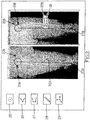
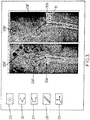
- the figures 2 and 3 show an example of a graphical interface that can be displayed on the screen 19 of the computer 37, or well on another screen.
- the graphical interface is identical; only the stereoscopic images displayed and the quantities measured vary.
- This graphical interface makes it possible to display the stereoscopic images 20A, 20B, 20A ', 20B'.
- icons 25, 26, 27, 28, 29 There are also icons 25, 26, 27, 28, 29. Each of the icons 25, 26, 27, 28 corresponds to a type of geometrical quantity, for example 3 point angle, 4 point angle, distance. Icon 25 can correspond to a size of radius or diameter of a sphere.
- the figure 4 shows an example of an orthopedic measurement algorithm of geometric quantities intrinsic to an osteo-articular system, from two stereoscopic geometrically calibrated views of this osteo-articular system. These two images can be obtained using the figure 1 , and be displayed on the graphical interface of figures 2 and 3 . The figures 2 , 3 and 4 will be commented on simultaneously.
- the user can start by clicking on one of the icons 25 to 29, so that the processor (reference 17 on the figure 1 ) receives during a step 40 information relating to the type of geometric quantity that the user wishes to measure.
- the user selects certain points on the images 20A, 20B, 20A ', 20B'.
- the device thus receives, during a step (a) location data comprising sets of two-dimensional coordinates, each set of two-dimensional coordinates comprising two pairs of two-dimensional coordinates corresponding to two points on the one and the other of the images respectively. stereoscopic.
- the number of sets of coordinates received varies depending on the icon selected.
- the end of acquisition test 41 therefore varies according to the information received in step 40.
- Test 41 therefore consists in comparing the number of sets of coordinates received with a threshold.
- this acquisition step (a) is terminated when four sets of coordinates are received.
- this acquisition step (a) is terminated when two sets of coordinates are received.
- the user can, in order to position two circles corresponding to the sphere respectively on the two images, on the one hand move these circles, and on the other hand stretch these circles.
- the device is therefore capable of receiving a number of sets of coordinates which may not be predefined.
- the test 41 can then consist in detecting this click.
- each pair of coordinates is located on a place of the possible of the corresponding image, this place of the possibilities being determinable from the other pair of coordinates and of geometric calibration information between the images.
- the sources references 5, 11 on the figure 1 , or S A , S B on the figure 5
- detectors references 6, 12 on the figure 1 , or D A , D B on the figure 5
- sets of coordinates defining points in 3D space.
- a step 42 for receiving a first pair of coordinates x A , y A that is to say that the user begins with select a point on one of the images 20A, called the first image.
- a line ⁇ 3D is defined in 3D space between a point P A on the detector D A corresponding to the coordinates x A , y A on the first image and a point S A in 3D space corresponding to the source. Then we simulate taking an image of this line ⁇ 3D with the other source (corresponding to point S B ) and the other detector (corresponding to point D B ). The location of the possible ⁇ therefore corresponds to the simulated image of this straight line ⁇ 3D on the other image 20B.
- Each point of this place of possible ⁇ of image 20B defines with the point corresponding to the coordinates x A , y A on image 20A a point of 3D space.
- This location of possible ⁇ is displayed on the second image 20B.
- the user then clicks on a point of this possible location on the second image 20B, so that the device receives, during a step 44, a second pair of coordinates x B , y B.
- Steps 42, 43, 44 represent a relatively simple tracking data acquisition algorithm. Additional steps, not shown, can be provided to give the user more freedom to fix the coordinate sets. For example, we could let the user choose to click on the second image elsewhere than on the place of the possibilities defined in step 43. A place of the possibilities on the first image would then be determined, defined by the new point clicked . The set of coordinates could thus be defined by successive selections.
- step (b) during which is determined, using geometric calibration information, at least one three-dimensional geometric primitive defined by at least part of the location data received in step (a).
- each pair of coordinates obtained corresponds to a pair of points P A , P B on the figure 6 , and at a point P 3D in 3D space.
- This point in 3D space can be determined relatively easily, using for example the relative positions of sources and detectors. And once the point or points of 3D space have been determined, it is relatively easy for a person skilled in the art to obtain geometric primitives of the straight lines, spheres, or other type.
- step (a) For example, if the user has chosen to measure a 3-point angle, the three sets of coordinates received in step (a) make it possible to define, using the calibration information, three points in 3D space. These three points in 3D space make it possible to define two straight lines competing at a point (step 45).
- step (a) For example, if the user has chosen to measure a 4-point angle, the four sets of coordinates received in step (a) allow two lines of 3D space to be defined in step 45.
- step (a) For example, if the user chose to measure a distance, the two sets of coordinates received in step (a) make it possible to define two points of 3D space, or a straight line segment of 3D space during step 45.
- the sets of coordinates received make it possible to define a sphere of 3D space during step 45.
- step (c) one calculates from at least one three-dimensional geometric primitive determined in step (b) a value of geometric magnitude intrinsic to the osteoarticular system of the two stereoscopic images.
- an angle between these two lines is calculated from the two lines defined in step 45.
- the distance in 3D space is calculated between the two points of 3D space determined during step 45.
- a radius of the sphere is determined from the sphere defined in step 45.
- step (b) a sphere is defined in 3D space from these adjusted circles 21A, 21B.
- the radius of the sphere can be determined during step (c) and can provide information as to the size of the patient's condyle, for example for prosthesis manufacturing applications.
- the sphere defined in step (b) can be used to determine the position in 3D space of its center. Indeed, it can be difficult for the practitioner to locate the center of a condyle by simple point scoring. In passing through a primitive sphere, the practitioner uses the representations of the edges of the condyles on the images to determine this center.
- the position in 3D space of this center obtained following step (b) of definition of the sphere primitive, can itself be used to define other geometric primitives.
- step (b) we are trying to measure a distance in 3D space between the center of the condyle and the other end of the femur.
- a point in 3D space corresponding to this other end is defined in step (b), from a set of coordinates received in step (a) corresponding to points 23A, 23B.
- step (c) a distance in 3D space is calculated between these two points in 3D space.
- a distance in 3D space of 42.4 cm is obtained (reference 24).
- the distances 22A, 22B measured directly in the planes of the images, between the centers of the circles 20A, 20B and the points 23A, 23B respectively are 42.2 cm and 42.1 cm.
- the practitioner also used a primitive sphere to determine a point in 3D space corresponding to the center of a condyle.
- Two other points in 3D space are defined from two sets of coordinates received in step (a).
- an angle in 3D space is calculated from the positions in 3D space of these three points.
- the graphical interface of figures 2 and 3 has an icon 29, called the local marker icon. This icon is used to define a local coordinate system, using sets of coordinates entered by the practitioner.
- the practitioner clicks on this icon, he manipulates two-dimensional representations of a three-dimensional coordinate system, in the same way as it manipulates circles when it clicks on the icon 25.
- the practitioner can therefore position and orient these representations of the local coordinate system, so that can be defined in step (b) a local coordinate system in 3D space, from the geometric calibration information and from sets of coordinates entered by the practitioner during positioning / orientation.
- This local coordinate system defined in 3D space makes it possible in particular to define at least one plane of 3D space, for example the XY plane of the local coordinate system and / or the XZ plane.
- step (b) includes a test step 46: if some of the tracking data received in step (a) correspond to a 3D mark, a local mark is defined during a step 47.
- step (c) of calculating a geometric quantity to project all or part of the primitives obtained in step (b) other than this 3D coordinate system in one or more planes of the 3D coordinate system.
- the lines defined in 3D space during step (b) are projected into one of the planes also defined in step (b).
- One or more values of geometric quantities are then calculated from this or these projections in one or more planes of the local coordinate system.
- the local coordinate system defined in 3D space makes it possible in particular to define at least one axis of 3D space, for example the X axis of the local coordinate system, the Y axis and / or the Z axis. It can be envisaged, during step (c) of calculating a geometric quantity, to project all or part of the primitives obtained in step (b) other than this 3D coordinate system in one or more axes of the 3D coordinate system.
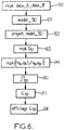
- the figure 6 shows another algorithm, in which two sets of imaging data are received in a step 60. Two stereoscopic images obtained from these sets are displayed. The practitioner can spot certain particular points on both of the images. A 3D model is reconstructed from these images, from an a priori model of the structure to be reconstructed, and from particular points paired from one image to another (step 61).
- the model obtained is projected onto two non-parallel planes, for example defined by the practitioner, during a step 62.
- the practitioner may then wish to carry out measurements of geometric quantities intrinsic to the osteoarticular system of the patient.
- the practitioner clicks on one of the icons 25 to 29, so that an indication of the type of quantity which it is desired to measure is received during a step 62.
- Identification data are received during a step ( a)
- geometric primitives are determined during a step (b) and a quantity G 3D is calculated from these primitives , during a step (c). This quantity G 3D is displayed on a screen during a step 64.
Landscapes
- Health & Medical Sciences (AREA)
- Life Sciences & Earth Sciences (AREA)
- Engineering & Computer Science (AREA)
- Medical Informatics (AREA)
- Heart & Thoracic Surgery (AREA)
- Animal Behavior & Ethology (AREA)
- Biophysics (AREA)
- Veterinary Medicine (AREA)
- Public Health (AREA)
- Pathology (AREA)
- General Health & Medical Sciences (AREA)
- Biomedical Technology (AREA)
- Physics & Mathematics (AREA)
- Molecular Biology (AREA)
- Surgery (AREA)
- Radiology & Medical Imaging (AREA)
- High Energy & Nuclear Physics (AREA)
- Optics & Photonics (AREA)
- Nuclear Medicine, Radiotherapy & Molecular Imaging (AREA)
- Human Computer Interaction (AREA)
- Computer Vision & Pattern Recognition (AREA)
- Dentistry (AREA)
- Oral & Maxillofacial Surgery (AREA)
- Orthopedic Medicine & Surgery (AREA)
- Rheumatology (AREA)
- Image Processing (AREA)
- Apparatus For Radiation Diagnosis (AREA)
Claims (10)
- Messverfahren für geometrische Größen, die intrinsisch für ein anatomisches System sind, ausgehend von zwei geometrisch kalibrierten, zweidimensionalen, stereoskopischen Bildern des anatomischen Systems eines Patienten, umfassend:(a) Empfangen von Ortsdaten, die mehrere Sätze zweidimensionaler Koordinaten umfassen, wobei jeder Satz zweidimensionaler Koordinaten ein erstes Paar (xA, yA) zweidimensionaler Koordinaten umfasst, das einem ersten Punkt auf einem der beiden stereoskopischen Bilder entspricht, und
ein zweites Paar (xB, yB) zweidimensionaler Koordinaten umfasst, das einem zweiten Punkt auf dem anderen der beiden stereoskopischen Bilder entspricht,(b) Bestimmen mindestens einer dreidimensionalen geometrischen Grundform (), welche durch wenigstens einen Teil der in Schritt (a) empfangenen Ortsdaten definiert wird, unter Verwendung von geometrischen Kalibrierungsinformationen, (c) Berechnen eines Wertes der für das anatomische System intrinsischen geometrischen Größe (G3D) auf Grundlage von wenigstens einer im Schritt (b) bestimmten dreidimensionalen geometrischen Grundform, wobei in Schritt (c) mindestens ein Wert der geometrischen Größe in mindestens einer Ebene berechnet wird, ausgehend von mindestens einer Projektion mindestens einer in Schritt (b) bestimmten dreidimensionalen geometrischen Grundform auf die mindestens eine Ebene, wobei die Ebene auf Grundlage von in Schritt (a) empfangenen Ortsdaten definiert wird, wobei eine dreidimensionale geometrische Grundform eine Kugel, eine Gerade, ein Zylinder, ein Kegel oder ein Klotz ist,
und wobei die geometrische Größe ein Winkel oder ein Flächeninhalt ist. - Messverfahren nach Anspruch 1, wobei die beiden stereoskopischen Bilder durch jeweils zwei Projektionen (62) eines dreidimensionalen Modells des Osteo-Gelenk-Systems des Patienten in unterschiedlichen Richtungen auf virtuelle Ebenen erhalten werden, die Aufnahme-Ebenen simulieren.
- Messverfahren nach Anspruch 1, wobei die beiden stereoskopischen Bilder von zwei jeweiligen Röntgendetektoren empfangen werden.
- Messverfahren nach einem der vorhergehenden Ansprüche, bei dem in Schritt (a) die Ortsdaten empfangen werden, nachdem ein Benutzer mit Hilfe einer Benutzerschnittstelle Punkte auf den Bildern ausgewählt hat.
- Messverfahren nach einem der vorhergehenden Ansprüche, ferner umfassend einen Schritt des Anzeigens des in Schritt (c) berechneten Werts der geometrischen Größe auf einem Bildschirm.
- Messverfahren nach Anspruch 5, bei dem nach dem Schritt des Anzeigens die Schritte (a), (b), (c) und der Schritt des Anzeigens wiederholt werden.
- Messverfahren nach einem der vorhergehenden Ansprüche, wobei die in Schritt (a) empfangenen Ortsdaten drei oder vier Sätze zweidimensionaler Koordinaten umfassen.
- Messverfahren nach dem vorhergehenden Anspruch, wobei die geometrische Größe, deren Wert in Schritt (c) berechnet wird, ein Winkel ist.
- Computerprogramm mit Anweisungen zur Durchführung des Verfahrens nach einem der vorhergehenden Ansprüche, wenn die Anweisungen von einem Prozessor ausgeführt werden.
- Vorrichtung (17) zum Messen geometrischer Größen, die intrinsisch für ein anatomisches System sind, ausgehend von zwei geometrisch kalibrierten, stereoskopischen, zweidimensionalen Bildern des anatomischen Systems eines Patienten, umfassend:(a) Empfangsmittel für Ortsdaten, die mehrere Sätze von zweidimensionalen Koordinaten umfassen, wobei jeder Satz von zweidimensionalen Koordinaten ein erstes Paar von zweidimensionalen Koordinaten umfasst, das einem ersten Punkt auf einem der beiden stereoskopischen Bilder entspricht, und ein zweites Paar von zweidimensionalen Koordinaten umfasst, das einem zweiten Punkt auf dem anderen der beiden stereoskopischen Bilder entspricht,(b) Verarbeitungsmittel, die dazu ausgelegt sind, unter Verwendung von geometrischen Kalibrierungsinformationen mindestens eine dreidimensionale geometrische Grundform zu bestimmen, die durch mindestens einen Teil der von den Empfangsmitteln empfangenen Ortsdaten definiert ist,
und dazu, ausgehend von mindestens einer so bestimmten dreidimensionalen geometrischen Grundform einen Wert der geometrischen Größe zu berechnen, die intrinsisch für das anatomische System ist,
wobei eine dreidimensionale geometrische Grundform eine Kugel, eine Gerade, ein Zylinder, ein Kegel oder ein Klotz ist,
und so dass mindestens ein Wert der geometrischen Größe in mindestens einer Ebene berechnet wird, ausgehend von mindestens einer Projektion mindestens einer bestimmten dreidimensionalen geometrischen Grundform auf die mindestens eine Ebene, wobei die Ebene auf der Grundlage von empfangenen Ortsdaten definiert ist,
wobei die geometrische Größe ein Winkel oder ein Flächeninhalt ist.
Applications Claiming Priority (1)
| Application Number | Priority Date | Filing Date | Title |
|---|---|---|---|
| FR0857245A FR2937530B1 (fr) | 2008-10-24 | 2008-10-24 | Mesure de grandeurs geometriques intrinseques a un systeme anatomique |
Publications (2)
| Publication Number | Publication Date |
|---|---|
| EP2186479A1 EP2186479A1 (de) | 2010-05-19 |
| EP2186479B1 true EP2186479B1 (de) | 2020-04-15 |
Family
ID=40361597
Family Applications (1)
| Application Number | Title | Priority Date | Filing Date |
|---|---|---|---|
| EP09161145.9A Active EP2186479B1 (de) | 2008-10-24 | 2009-05-26 | Messung intrinsischer geometrischer Größenmaße eines anatomischen Systems |
Country Status (3)
| Country | Link |
|---|---|
| US (1) | US8705817B2 (de) |
| EP (1) | EP2186479B1 (de) |
| FR (1) | FR2937530B1 (de) |
Families Citing this family (28)
| Publication number | Priority date | Publication date | Assignee | Title |
|---|---|---|---|---|
| US10070903B2 (en) | 2008-01-09 | 2018-09-11 | Stryker European Holdings I, Llc | Stereotactic computer assisted surgery method and system |
| US10588647B2 (en) | 2010-03-01 | 2020-03-17 | Stryker European Holdings I, Llc | Computer assisted surgery system |
| GB201008281D0 (en) | 2010-05-19 | 2010-06-30 | Nikonovas Arkadijus | Indirect analysis and manipulation of objects |
| CA2804812C (en) | 2010-07-16 | 2015-02-17 | Stryker Trauma Gmbh | Surgical targeting system and method |
| US12367578B2 (en) | 2010-12-07 | 2025-07-22 | University Of Iowa Research Foundation | Diagnosis of a disease condition using an automated diagnostic model |
| WO2012078636A1 (en) | 2010-12-07 | 2012-06-14 | University Of Iowa Research Foundation | Optimal, user-friendly, object background separation |
| EP2665406B1 (de) | 2011-01-20 | 2021-03-10 | University of Iowa Research Foundation | Automatische bestimmung des arteriovenösen verhältnisses in bildern von blutgefässen |
| US20140035909A1 (en) * | 2011-01-20 | 2014-02-06 | University Of Iowa Research Foundation | Systems and methods for generating a three-dimensional shape from stereo color images |
| JP6005905B2 (ja) * | 2011-04-06 | 2016-10-12 | 東芝メディカルシステムズ株式会社 | 画像処理システム、画像処理装置及び画像処理方法 |
| US9545196B2 (en) | 2012-05-04 | 2017-01-17 | University Of Iowa Research Foundation | Automated assessment of glaucoma loss from optical coherence tomography |
| WO2014048447A1 (en) * | 2012-09-27 | 2014-04-03 | Stryker Trauma Gmbh | Rotational position determination |
| US8864763B2 (en) | 2013-03-13 | 2014-10-21 | DePuy Synthes Products, LLC | External bone fixation device |
| US9039706B2 (en) | 2013-03-13 | 2015-05-26 | DePuy Synthes Products, Inc. | External bone fixation device |
| JP6382293B2 (ja) | 2013-03-13 | 2018-08-29 | デピュイ・シンセス・プロダクツ・インコーポレイテッド | 外部骨固定装置 |
| WO2014143891A1 (en) | 2013-03-15 | 2014-09-18 | University Of Iowa Research Foundation | Automated separation of binary overlapping trees |
| KR20150027881A (ko) * | 2013-08-29 | 2015-03-13 | 삼성전자주식회사 | 엑스선 영상 장치 및 그 제어방법 |
| US10410355B2 (en) | 2014-03-21 | 2019-09-10 | U.S. Department Of Veterans Affairs | Methods and systems for image analysis using non-euclidean deformed graphs |
| US10115194B2 (en) | 2015-04-06 | 2018-10-30 | IDx, LLC | Systems and methods for feature detection in retinal images |
| US10777315B2 (en) | 2015-10-13 | 2020-09-15 | Mazor Robotics Ltd. | Global spinal alignment method |
| US10835318B2 (en) | 2016-08-25 | 2020-11-17 | DePuy Synthes Products, Inc. | Orthopedic fixation control and manipulation |
| US12380572B2 (en) | 2018-04-12 | 2025-08-05 | Veran Medical Technologies, Inc. | Methods for the segmentation of lungs, lung vasculature and lung lobes from CT data and clinical applications |
| US10643333B2 (en) * | 2018-04-12 | 2020-05-05 | Veran Medical Technologies | Apparatuses and methods for navigation in and Local segmentation extension of anatomical treelike structures |
| CN109602428B (zh) * | 2018-11-05 | 2022-07-22 | 上海逸动医学科技有限公司 | 一种移动式双平面x光系统的立体动态定位系统 |
| US11439436B2 (en) | 2019-03-18 | 2022-09-13 | Synthes Gmbh | Orthopedic fixation strut swapping |
| US11304757B2 (en) | 2019-03-28 | 2022-04-19 | Synthes Gmbh | Orthopedic fixation control and visualization |
| US11334997B2 (en) | 2020-04-03 | 2022-05-17 | Synthes Gmbh | Hinge detection for orthopedic fixation |
| CN111588394A (zh) * | 2020-06-12 | 2020-08-28 | 中国人民解放军空军军医大学 | 一种人体骨关节运动学动态采集系统 |
| WO2025108562A1 (en) * | 2023-11-24 | 2025-05-30 | Eos Imaging | Method of radiography of a patient body |
Family Cites Families (17)
| Publication number | Priority date | Publication date | Assignee | Title |
|---|---|---|---|---|
| FR2705223A1 (fr) * | 1993-05-13 | 1994-11-25 | Ge Medical Syst Sa | Procédé d'acquisition d'images d'un corps par placement en rotation. |
| FR2749402B1 (fr) | 1996-05-29 | 1998-08-07 | Charpak Georges | Dispositif d'imagerie radiographique a haute resolution |
| US6614452B1 (en) | 1999-11-15 | 2003-09-02 | Xenogen Corporation | Graphical user interface for in-vivo imaging |
| US7581191B2 (en) * | 1999-11-15 | 2009-08-25 | Xenogen Corporation | Graphical user interface for 3-D in-vivo imaging |
| WO2001093745A2 (en) | 2000-06-06 | 2001-12-13 | The Research Foundation Of State University Of New York | Computer aided visualization, fusion and treatment planning |
| FR2810769B1 (fr) * | 2000-06-23 | 2002-10-11 | Biospace Instr | Procede et dispositif d'imagerie radiographique pour la reconstitution tridimensionnelle a faible dose d'irradiation |
| JP4488678B2 (ja) * | 2001-02-07 | 2010-06-23 | アーオー テクノロジー アクチエンゲゼルシャフト | 骨のx線画像の三次元表示の確立方法 |
| US7717708B2 (en) | 2001-04-13 | 2010-05-18 | Orametrix, Inc. | Method and system for integrated orthodontic treatment planning using unified workstation |
| WO2004069040A2 (en) * | 2003-02-04 | 2004-08-19 | Z-Kat, Inc. | Method and apparatus for computer assistance with intramedullary nail procedure |
| FR2856170B1 (fr) * | 2003-06-10 | 2005-08-26 | Biospace Instr | Procede d'imagerie radiographique pour la reconstruction tridimensionnelle, dispositif et programme d'ordinateur pour mettre en oeuvre ce procede |
| US7794398B2 (en) | 2003-09-29 | 2010-09-14 | Koninklijke Philips Electronics N.V. | Real-time volumetric bi-plane ultrasound imaging and quantification |
| EP1975877B1 (de) | 2005-11-23 | 2018-09-19 | Agfa HealthCare N.V. | Verfahren zur Anziehung eines Interessenspunktes bei Digitalbildern |
| US7885705B2 (en) * | 2006-02-10 | 2011-02-08 | Murphy Stephen B | System and method for facilitating hip surgery |
| DE102006041055B4 (de) | 2006-09-01 | 2015-10-15 | Siemens Aktiengesellschaft | Verfahren zur Unterstützung der Durchführung einer endoskopischen medizinischen Maßnahme sowie mit diesem Verfahren betreibbare Einrichtung |
| US7440540B2 (en) * | 2006-10-05 | 2008-10-21 | Bassel Kano | Stereoscopic x-ray system and method |
| IL184151A0 (en) | 2007-06-21 | 2007-10-31 | Diagnostica Imaging Software Ltd | X-ray measurement method |
| JP4996366B2 (ja) * | 2007-06-28 | 2012-08-08 | 株式会社東芝 | 3次元構造データ作成装置 |
-
2008
- 2008-10-24 FR FR0857245A patent/FR2937530B1/fr not_active Expired - Fee Related
-
2009
- 2009-05-26 EP EP09161145.9A patent/EP2186479B1/de active Active
- 2009-05-27 US US12/473,258 patent/US8705817B2/en active Active
Non-Patent Citations (1)
| Title |
|---|
| None * |
Also Published As
| Publication number | Publication date |
|---|---|
| US8705817B2 (en) | 2014-04-22 |
| FR2937530A1 (fr) | 2010-04-30 |
| US20100104150A1 (en) | 2010-04-29 |
| EP2186479A1 (de) | 2010-05-19 |
| FR2937530B1 (fr) | 2012-02-24 |
Similar Documents
| Publication | Publication Date | Title |
|---|---|---|
| EP2186479B1 (de) | Messung intrinsischer geometrischer Größenmaße eines anatomischen Systems | |
| EP1168249B1 (de) | Verfahren und Vorrichtung zur dreidimensionalen Rekonstruktion von Röntgenbilder mit niedriger Strahlungsdosis | |
| EP1788525B1 (de) | Bildgebendes Verfahren für die dreidimensionale Rekonstruktion, Vorrichtung und Computerprogramm zur Durchführung besagten Verfahrens | |
| US6081739A (en) | Scanning device or methodology to produce an image incorporating correlated superficial, three dimensional surface and x-ray images and measurements of an object | |
| EP2059904B1 (de) | Computergestütztes bildaufnahmeverfahren zur dreidimensionalen rekonstruktion aus zweidimensionalen radiologischen bildern und vorrichtung zu dessen ausführung | |
| EP1233700B1 (de) | Verfahren zur anwendung eines knochendichtemessungssystems mittels röntgenstrahlung bei zwei energien | |
| WO2024013642A2 (en) | Optimizing camera calibration targets for 2d to 3d reconstruction | |
| EP1246565B1 (de) | Auswertungseinrichtung des gleichgewichtstandes des menschlichen körpers | |
| FR2849241A1 (fr) | Procede et dispositif d'imagerie radiographique | |
| FR3068880A1 (fr) | Procede et systeme de calibration en ligne d'un dispositif medical a rayons x | |
| FR2692773A1 (fr) | Dispositif de corrélation des saisies tridimensionnelles d'organes humains. | |
| CN107752979A (zh) | 对人工投影的自动生成 | |
| EP1511421B1 (de) | Stereoradiographie-vorrichtung und anwendungsverfahren dafür | |
| WO2020169515A1 (fr) | Procédés et systèmes de traitement d'images | |
| CN114119801B (zh) | 三维数字减影血管造影方法、装置、电子设备及存储介质 | |
| US11380006B2 (en) | Size measurement using angle-constrained radiographic imaging | |
| WO2005076038A1 (en) | Method and apparatus for providing high-resolution reconstruction of an observed object | |
| EP3166476A1 (de) | System und verfahren für dreidimensionale tiefenbildgebung | |
| EP4396528B1 (de) | Verfahren und werkzeug zur kalibrierung eines passiven positionierungssystems | |
| EP3931799A1 (de) | Interventionelle vorrichtungsverfolgung | |
| JP3667727B2 (ja) | 物体の位置測定方法及びその装置 | |
| EP0689048B1 (de) | Verfahren zur Erreichung eines Bildes eines um eine Achse rotierenden Gegenstandes, mit Verwendung der Tangentialradiographie | |
| WO2025240638A1 (en) | Three-dimensional (3d) cadmium-zinc-telluride (czt) detector system for extended reality intrasurgical guidance | |
| WO2023031168A1 (fr) | Procédé de visualisation en temps réel d'un signal de contrôle non destructif d'une pièce mécanique | |
| WO2016177792A1 (fr) | Procede de generation d'un modele virtuel en trois dimensions d'au moins une partie d'un squelette d'un individu |
Legal Events
| Date | Code | Title | Description |
|---|---|---|---|
| PUAI | Public reference made under article 153(3) epc to a published international application that has entered the european phase |
Free format text: ORIGINAL CODE: 0009012 |
|
| AK | Designated contracting states |
Kind code of ref document: A1 Designated state(s): AT BE BG CH CY CZ DE DK EE ES FI FR GB GR HR HU IE IS IT LI LT LU LV MC MK MT NL NO PL PT RO SE SI SK TR |
|
| AX | Request for extension of the european patent |
Extension state: AL BA RS |
|
| 17P | Request for examination filed |
Effective date: 20101110 |
|
| 17Q | First examination report despatched |
Effective date: 20101124 |
|
| RAP1 | Party data changed (applicant data changed or rights of an application transferred) |
Owner name: EOS IMAGING |
|
| STAA | Information on the status of an ep patent application or granted ep patent |
Free format text: STATUS: EXAMINATION IS IN PROGRESS |
|
| GRAP | Despatch of communication of intention to grant a patent |
Free format text: ORIGINAL CODE: EPIDOSNIGR1 |
|
| STAA | Information on the status of an ep patent application or granted ep patent |
Free format text: STATUS: GRANT OF PATENT IS INTENDED |
|
| INTG | Intention to grant announced |
Effective date: 20191114 |
|
| GRAS | Grant fee paid |
Free format text: ORIGINAL CODE: EPIDOSNIGR3 |
|
| GRAA | (expected) grant |
Free format text: ORIGINAL CODE: 0009210 |
|
| STAA | Information on the status of an ep patent application or granted ep patent |
Free format text: STATUS: THE PATENT HAS BEEN GRANTED |
|
| AK | Designated contracting states |
Kind code of ref document: B1 Designated state(s): AT BE BG CH CY CZ DE DK EE ES FI FR GB GR HR HU IE IS IT LI LT LU LV MC MK MT NL NO PL PT RO SE SI SK TR |
|
| REG | Reference to a national code |
Ref country code: GB Ref legal event code: FG4D Free format text: NOT ENGLISH Ref country code: CH Ref legal event code: EP |
|
| REG | Reference to a national code |
Ref country code: DE Ref legal event code: R096 Ref document number: 602009061719 Country of ref document: DE |
|
| REG | Reference to a national code |
Ref country code: IE Ref legal event code: FG4D Free format text: LANGUAGE OF EP DOCUMENT: FRENCH |
|
| REG | Reference to a national code |
Ref country code: AT Ref legal event code: REF Ref document number: 1256345 Country of ref document: AT Kind code of ref document: T Effective date: 20200515 |
|
| REG | Reference to a national code |
Ref country code: NL Ref legal event code: MP Effective date: 20200415 |
|
| REG | Reference to a national code |
Ref country code: LT Ref legal event code: MG4D |
|
| PG25 | Lapsed in a contracting state [announced via postgrant information from national office to epo] |
Ref country code: FI Free format text: LAPSE BECAUSE OF FAILURE TO SUBMIT A TRANSLATION OF THE DESCRIPTION OR TO PAY THE FEE WITHIN THE PRESCRIBED TIME-LIMIT Effective date: 20200415 Ref country code: NO Free format text: LAPSE BECAUSE OF FAILURE TO SUBMIT A TRANSLATION OF THE DESCRIPTION OR TO PAY THE FEE WITHIN THE PRESCRIBED TIME-LIMIT Effective date: 20200715 Ref country code: SE Free format text: LAPSE BECAUSE OF FAILURE TO SUBMIT A TRANSLATION OF THE DESCRIPTION OR TO PAY THE FEE WITHIN THE PRESCRIBED TIME-LIMIT Effective date: 20200415 Ref country code: NL Free format text: LAPSE BECAUSE OF FAILURE TO SUBMIT A TRANSLATION OF THE DESCRIPTION OR TO PAY THE FEE WITHIN THE PRESCRIBED TIME-LIMIT Effective date: 20200415 Ref country code: LT Free format text: LAPSE BECAUSE OF FAILURE TO SUBMIT A TRANSLATION OF THE DESCRIPTION OR TO PAY THE FEE WITHIN THE PRESCRIBED TIME-LIMIT Effective date: 20200415 Ref country code: PT Free format text: LAPSE BECAUSE OF FAILURE TO SUBMIT A TRANSLATION OF THE DESCRIPTION OR TO PAY THE FEE WITHIN THE PRESCRIBED TIME-LIMIT Effective date: 20200817 Ref country code: GR Free format text: LAPSE BECAUSE OF FAILURE TO SUBMIT A TRANSLATION OF THE DESCRIPTION OR TO PAY THE FEE WITHIN THE PRESCRIBED TIME-LIMIT Effective date: 20200716 Ref country code: IS Free format text: LAPSE BECAUSE OF FAILURE TO SUBMIT A TRANSLATION OF THE DESCRIPTION OR TO PAY THE FEE WITHIN THE PRESCRIBED TIME-LIMIT Effective date: 20200815 |
|
| REG | Reference to a national code |
Ref country code: AT Ref legal event code: MK05 Ref document number: 1256345 Country of ref document: AT Kind code of ref document: T Effective date: 20200415 |
|
| PG25 | Lapsed in a contracting state [announced via postgrant information from national office to epo] |
Ref country code: HR Free format text: LAPSE BECAUSE OF FAILURE TO SUBMIT A TRANSLATION OF THE DESCRIPTION OR TO PAY THE FEE WITHIN THE PRESCRIBED TIME-LIMIT Effective date: 20200415 Ref country code: LV Free format text: LAPSE BECAUSE OF FAILURE TO SUBMIT A TRANSLATION OF THE DESCRIPTION OR TO PAY THE FEE WITHIN THE PRESCRIBED TIME-LIMIT Effective date: 20200415 Ref country code: BG Free format text: LAPSE BECAUSE OF FAILURE TO SUBMIT A TRANSLATION OF THE DESCRIPTION OR TO PAY THE FEE WITHIN THE PRESCRIBED TIME-LIMIT Effective date: 20200715 |
|
| REG | Reference to a national code |
Ref country code: DE Ref legal event code: R097 Ref document number: 602009061719 Country of ref document: DE |
|
| PG25 | Lapsed in a contracting state [announced via postgrant information from national office to epo] |
Ref country code: CH Free format text: LAPSE BECAUSE OF NON-PAYMENT OF DUE FEES Effective date: 20200531 Ref country code: EE Free format text: LAPSE BECAUSE OF FAILURE TO SUBMIT A TRANSLATION OF THE DESCRIPTION OR TO PAY THE FEE WITHIN THE PRESCRIBED TIME-LIMIT Effective date: 20200415 Ref country code: RO Free format text: LAPSE BECAUSE OF FAILURE TO SUBMIT A TRANSLATION OF THE DESCRIPTION OR TO PAY THE FEE WITHIN THE PRESCRIBED TIME-LIMIT Effective date: 20200415 Ref country code: CZ Free format text: LAPSE BECAUSE OF FAILURE TO SUBMIT A TRANSLATION OF THE DESCRIPTION OR TO PAY THE FEE WITHIN THE PRESCRIBED TIME-LIMIT Effective date: 20200415 Ref country code: LI Free format text: LAPSE BECAUSE OF NON-PAYMENT OF DUE FEES Effective date: 20200531 Ref country code: IT Free format text: LAPSE BECAUSE OF FAILURE TO SUBMIT A TRANSLATION OF THE DESCRIPTION OR TO PAY THE FEE WITHIN THE PRESCRIBED TIME-LIMIT Effective date: 20200415 Ref country code: ES Free format text: LAPSE BECAUSE OF FAILURE TO SUBMIT A TRANSLATION OF THE DESCRIPTION OR TO PAY THE FEE WITHIN THE PRESCRIBED TIME-LIMIT Effective date: 20200415 Ref country code: MC Free format text: LAPSE BECAUSE OF FAILURE TO SUBMIT A TRANSLATION OF THE DESCRIPTION OR TO PAY THE FEE WITHIN THE PRESCRIBED TIME-LIMIT Effective date: 20200415 Ref country code: AT Free format text: LAPSE BECAUSE OF FAILURE TO SUBMIT A TRANSLATION OF THE DESCRIPTION OR TO PAY THE FEE WITHIN THE PRESCRIBED TIME-LIMIT Effective date: 20200415 Ref country code: DK Free format text: LAPSE BECAUSE OF FAILURE TO SUBMIT A TRANSLATION OF THE DESCRIPTION OR TO PAY THE FEE WITHIN THE PRESCRIBED TIME-LIMIT Effective date: 20200415 |
|
| PLBE | No opposition filed within time limit |
Free format text: ORIGINAL CODE: 0009261 |
|
| STAA | Information on the status of an ep patent application or granted ep patent |
Free format text: STATUS: NO OPPOSITION FILED WITHIN TIME LIMIT |
|
| PG25 | Lapsed in a contracting state [announced via postgrant information from national office to epo] |
Ref country code: PL Free format text: LAPSE BECAUSE OF FAILURE TO SUBMIT A TRANSLATION OF THE DESCRIPTION OR TO PAY THE FEE WITHIN THE PRESCRIBED TIME-LIMIT Effective date: 20200415 Ref country code: SK Free format text: LAPSE BECAUSE OF FAILURE TO SUBMIT A TRANSLATION OF THE DESCRIPTION OR TO PAY THE FEE WITHIN THE PRESCRIBED TIME-LIMIT Effective date: 20200415 |
|
| REG | Reference to a national code |
Ref country code: BE Ref legal event code: MM Effective date: 20200531 |
|
| 26N | No opposition filed |
Effective date: 20210118 |
|
| PG25 | Lapsed in a contracting state [announced via postgrant information from national office to epo] |
Ref country code: LU Free format text: LAPSE BECAUSE OF NON-PAYMENT OF DUE FEES Effective date: 20200526 |
|
| PG25 | Lapsed in a contracting state [announced via postgrant information from national office to epo] |
Ref country code: IE Free format text: LAPSE BECAUSE OF NON-PAYMENT OF DUE FEES Effective date: 20200526 |
|
| PG25 | Lapsed in a contracting state [announced via postgrant information from national office to epo] |
Ref country code: SI Free format text: LAPSE BECAUSE OF FAILURE TO SUBMIT A TRANSLATION OF THE DESCRIPTION OR TO PAY THE FEE WITHIN THE PRESCRIBED TIME-LIMIT Effective date: 20200415 Ref country code: BE Free format text: LAPSE BECAUSE OF NON-PAYMENT OF DUE FEES Effective date: 20200531 |
|
| PG25 | Lapsed in a contracting state [announced via postgrant information from national office to epo] |
Ref country code: TR Free format text: LAPSE BECAUSE OF FAILURE TO SUBMIT A TRANSLATION OF THE DESCRIPTION OR TO PAY THE FEE WITHIN THE PRESCRIBED TIME-LIMIT Effective date: 20200415 Ref country code: MT Free format text: LAPSE BECAUSE OF FAILURE TO SUBMIT A TRANSLATION OF THE DESCRIPTION OR TO PAY THE FEE WITHIN THE PRESCRIBED TIME-LIMIT Effective date: 20200415 Ref country code: CY Free format text: LAPSE BECAUSE OF FAILURE TO SUBMIT A TRANSLATION OF THE DESCRIPTION OR TO PAY THE FEE WITHIN THE PRESCRIBED TIME-LIMIT Effective date: 20200415 |
|
| PG25 | Lapsed in a contracting state [announced via postgrant information from national office to epo] |
Ref country code: MK Free format text: LAPSE BECAUSE OF FAILURE TO SUBMIT A TRANSLATION OF THE DESCRIPTION OR TO PAY THE FEE WITHIN THE PRESCRIBED TIME-LIMIT Effective date: 20200415 |
|
| P01 | Opt-out of the competence of the unified patent court (upc) registered |
Effective date: 20230525 |
|
| PGFP | Annual fee paid to national office [announced via postgrant information from national office to epo] |
Ref country code: DE Payment date: 20250513 Year of fee payment: 17 |
|
| PGFP | Annual fee paid to national office [announced via postgrant information from national office to epo] |
Ref country code: GB Payment date: 20250521 Year of fee payment: 17 |
|
| PGFP | Annual fee paid to national office [announced via postgrant information from national office to epo] |
Ref country code: FR Payment date: 20250422 Year of fee payment: 17 |