EP2186579A2 - Outil de pliage et porte-outil pour une plieuse - Google Patents
Outil de pliage et porte-outil pour une plieuse Download PDFInfo
- Publication number
- EP2186579A2 EP2186579A2 EP09013145A EP09013145A EP2186579A2 EP 2186579 A2 EP2186579 A2 EP 2186579A2 EP 09013145 A EP09013145 A EP 09013145A EP 09013145 A EP09013145 A EP 09013145A EP 2186579 A2 EP2186579 A2 EP 2186579A2
- Authority
- EP
- European Patent Office
- Prior art keywords
- contact
- tool
- bending
- bending tool
- tool holder
- Prior art date
- Legal status (The legal status is an assumption and is not a legal conclusion. Google has not performed a legal analysis and makes no representation as to the accuracy of the status listed.)
- Granted
Links
Images

Classifications
-
- B—PERFORMING OPERATIONS; TRANSPORTING
- B21—MECHANICAL METAL-WORKING WITHOUT ESSENTIALLY REMOVING MATERIAL; PUNCHING METAL
- B21D—WORKING OR PROCESSING OF SHEET METAL OR METAL TUBES, RODS OR PROFILES WITHOUT ESSENTIALLY REMOVING MATERIAL; PUNCHING METAL
- B21D5/00—Bending sheet metal along straight lines, e.g. to form simple curves
- B21D5/02—Bending sheet metal along straight lines, e.g. to form simple curves on press brakes without making use of clamping means
- B21D5/0209—Tools therefor
-
- B—PERFORMING OPERATIONS; TRANSPORTING
- B21—MECHANICAL METAL-WORKING WITHOUT ESSENTIALLY REMOVING MATERIAL; PUNCHING METAL
- B21D—WORKING OR PROCESSING OF SHEET METAL OR METAL TUBES, RODS OR PROFILES WITHOUT ESSENTIALLY REMOVING MATERIAL; PUNCHING METAL
- B21D5/00—Bending sheet metal along straight lines, e.g. to form simple curves
- B21D5/02—Bending sheet metal along straight lines, e.g. to form simple curves on press brakes without making use of clamping means
- B21D5/0209—Tools therefor
- B21D5/0254—Tool exchanging
Definitions
- the invention relates to a bending tool according to the preamble of patent claim 1 and a tool holder according to the preamble of claim 15, further a bending machine according to the preamble of claim 19 and a method for electrical coupling of a bending tool with a tool holder according to the preamble of claim 20.
- press brakes can be used in the tool holders for upper tool or lower tool depending on the workpieces to be bent a variety of tools.
- the bending machines are equipped with programmable electronic control devices, which allow the execution of exact and optimized bending operations based on information about the workpiece to be bent and information about the respective bending tools used.
- Bending tools are already known for this purpose, which can be identified by the control device on the basis of information transmitted by the bending tool to the control device, or on which measuring elements, in particular electrical measuring sensors are arranged or integrated and thereby measured values, in particular information, during a bending operation can be transmitted to the control device via the bending process or the workpiece to be bent.
- This transfer takes place in many cases via electrical contacts which form an electrical interface between the bending tool and tool holder, wherein in the inserted state of the bending tools contacts are brought to a mounting portion of a bending tool with contacts on a receiving portion of the tool holder in touching electrical connection, whereby a functional element the bending tool, for example, an information carrier or a measuring element with a control device of the bending machine can be brought into connection.
- Currents flowing through such an electrical interface between the bending tool and the tool holder can serve both to supply energy to a functional element in the bending tool and to transfer data between the functional element and the control device.
- a disadvantage of this type of contact is that the contact pins protrude from the bending tool not used in the tool holder and therefore often mechanical stresses can be exposed, which can cause damage to the pins or the contact pin guides and the resilient mounting. Furthermore, when the bending tool is not approached in the direction of the contact pins on the tool holder, grinding operations between the contact pins and the tool holder take place, which cause wear of the contacting surfaces and therefore the electrical connection between the bending tool and tool holder is not ensured in the long run.
- the object of the invention is an interface for the electrical connection of a. Functional element to provide a bending tool with a contact surface on a tool holder of a bending machine, which permanently has a high reliability.
- a bending tool with the features of claim 1, according to which the bending tool comprises a coupling with a receiving portion of the tool holder mounting portion and an adjustably mounted contact element for electrically connecting a formed on the bending tool function element with a contact surface on the receiving portion of the tool holder, and in this case, the contact element can be moved outward by a contact element arranged on the receiving portion of the tool holder from a contact surface spaced rest position relative to an outer surface of the mounting portion in a contact surface contacting the contact position.
- the contact element for example, in the form of a contact pin, is therefore not as in the prior art by a contact surface on the tool holder from a rest position to pressed inside the contact position, but actively spent by a separate actuator on the tool holder from a rest position to the outside in a contact surface contacting contact position.
- a cooperating with the bending tool according to the invention inventive tool holder on a bending machine has according to claim 15 a receiving portion for coupling a mounting portion of a bending tool and an electrically conductive, connected to a power supply device or a control device contact surface on the receiving portion, wherein for an adjustment on the attachment portion of the bending tool between a rest position and a contact position adjustably mountedschreiblements on the receiving portion of the tool holder is an adjustably mounted, connected to an adjustment and the contact element in the contact position-bringing actuator is arranged.
- the object of the invention is further achieved by a method for electrically coupling a functional element on a bending tool with a contact surface on a tool holder by means of a bending tool adjustably mounted contact element, according to the invention in a first step, the bending tool is moved to its intended position on the tool holder and In a subsequent second step, the contact element is adjusted by means of an actuator formed on the tool holder from a distance to the contact surface rest position in a contact surface contacting the contact position.
- the actuator on the tool holder can act directly on the contact element mechanically, but it is also possible that a movement of the actuator is transmitted by means of an adjustable mounting portion on the transfer element mounted on the contact element, for example.
- a pressure piece or a pivot lever or the like can act directly on the contact element mechanically, but it is also possible that a movement of the actuator is transmitted by means of an adjustable mounting portion on the transfer element mounted on the contact element, for example.
- a pressure piece or a pivot lever or the like can act directly on the contact element mechanically, but it is also possible that a movement of the actuator is transmitted by means of an adjustable mounting portion on the transfer element mounted on the contact element, for example.
- a pressure piece or a pivot lever or the like can act directly on the contact element mechanically, but it is also possible that a movement of the actuator is transmitted by means of an adjustable mounting portion on the transfer element mounted on the contact element, for example.
- a pressure piece or a pivot lever or the like can act directly on the contact element mechanically, but it is also possible that a movement
- the at least one contact element if it is not actively spent by the actuator in the contact position, automatically assumes the rest position in which it has a distance to the contact surface of the tool holder or set back relative to the outer surface of the mounting portion, it is advantageous if in Attachment section is arranged on the contact element or the transmission element in the direction of the rest position acting spring element. Characterized the contact element is automatically spent after deactivation of the actuator of the tool holder by the spring element in the protected rest position.
- the contact element can thereby be guided approximately rectilinearly in the attachment section, whereby a gentle touching of the contact surface is ensured, in particular if the guide direction is oriented at right angles to the contact surface. Furthermore, a straight-line guide of the contact element may be advantageous if the actuating member and the contact surface are arranged approximately diametrically with respect to the fastening portion located therebetween on the tool holder.
- the contact element may be guided by means of a pivot bearing in the attachment portion, such as when the actuator and the contact surface on the tool holder are not diametrically opposed to each other and the adjustment of the actuator to the adjustment of the contact element forms an angle.
- the contact element may be designed for reasons of ease of manufacture as a cylindrical contact pin or pin.
- the spring element can be designed as a force acting on the contact element or the transmission element, in particular already biased in the rest position compression spring.
- This embodiment is useful when the contact element is designed as a rectilinear guided, cylindrical contact pin, wherein the compression spring can comprise the contact pin concentrically and is supported on a pinhole, which is mounted on the outer surface of the mounting portion.
- the flow of current to or from the functional element takes place in the simplest case on the one hand via the generally metallic bending tool that touches the metallic tool holder and on the other hand via the opposite electrically conductive contact element to the rest of the bending tool, but it can also be provided for the functional element two own, to each other and to provide the bending tool galvanically isolated contact elements. Furthermore, it is possible that a plurality of functional elements are arranged in a bending tool, which is why it may be advantageous if the actuating member acts on at least two contact elements or two transmission elements.
- the bending tool may also have a transmission element which acts on at least two contact elements. Due to these two Ausrrittungs. despite multiple contact elements can be dispensed with the use of multiple actuators or several transmission elements, resulting in structurally simple solutions.
- the guide sleeve can be formed in particular from a material selected from a group comprising metals and plastics with a low coefficient of sliding friction.
- an elastic connecting element is arranged between the contact element and the transmission element.
- the elastic connecting element can in turn be designed as a spring element, for example, as a compression spring or tension spring made of a metal or else be formed by a connecting element made of elastomeric material.
- it can be formed on the contact element itself or on the transmission element itself an elastically deformable portion that makes its own additional connection element dispensable by at least one of the two parts can deform so far that extreme contact forces are avoided when the adjustment of the actuator by a fixed Stop element is limited.
- the contact element has a hard-gold-plated surface at least in a contact section which possibly makes contact with the contact surface and which is additionally wear-resistant.
- the functional element can be formed on the bending tool by a measuring element, in particular an electrical measuring transducer, whereby, before, during or after machining and / or reshaping existing properties of the workpiece, such as mechanical variables detected and supplied to the control device of the bending machine can be.
- a measuring element in particular an electrical measuring transducer
- the measuring element can be designed in particular for detecting a geometric size of a workpiece to be machined with the bending tool, for example a bending angle on the workpiece in the loaded and / or unloaded state or, for example, the thickness of the workpiece before the bending deformation.
- the functional element can comprise a memory element, in particular for storing tool data, whereby the control device can be transferred either directly from the memory element parameters of the bending tool or after an identification of the bending tool used can be read in a memory stored outside the bending tool tool parameters.
- a simple construction of the tool holder can be achieved if the actuating member is formed by a fastening element fixing the fixing portion on the receiving portion.
- Such clamping elements are available in any case for the fixation of upper tools on the tool holder of an upper press beam anyway and can thereby be used simultaneously as an actuator for the contact element.
- the clamping element can be designed in particular as a wedge element, which cooperates with a keyway on the attachment portion of the bending tool. By acting between wedge element and keyway clamping forces can be a very stable and precise fixation of the bending tool on the tool holder and at the same time is one in the keyway arranged on the attachment portion actuator during handling outside the tool holder from damage well protected.
- the receiving portion of the tool holder comprises in an advantageous development of the invention, a tool holder groove in which the actuator and the contact surface can be arranged and are thus well protected from damage.
- the tool receiving groove extends in particular in the longitudinal direction of a press beam or a press table, whereby the position of the bending tool along the press beam or the press table can be chosen freely.
- the contact surface has, at least in sections, a hard-gold plated surface.
- the contact surface is formed on a contact rail extending in a longitudinal direction of the receiving portion and arranged in particular in a tool receiving groove.
- a plurality of mutually parallel contact rails may be formed.
- the contact surface may be formed by at least one conductor track mounted on an electrically insulating carrier element.
- the adjusting drive for the adjustment of the actuating member on the tool holder can be formed by a fluidically or electrically operated actuator.
- Fig. 1 shows a bending tool 1 during insertion into a tool holder 2 of a bending machine, not shown, in particular a press brake.
- the tool holder 2 is arranged on a press bar 3 shown in sections and has a flat receiving portion 4, to which a flat mounting portion 5 of the bending tool 1 can be coupled.
- the receiving portion 4 has a tool receiving groove 6, which is suitable for receiving a fastening extension 7 formed on the bending tool 1 or its attachment portion 5. Its outer contour substantially corresponds to the inner contour of the tool receiving groove 6, wherein between the tool receiving groove 6 and fastening extension 7 a required for the insertion or removal of the bending tool 1 functional game is available.
- the bending tool 1 can also be referred to as an upper tool 8, for example in the form of a bending punch 9, which cooperates with a lower tool (not shown), for example in the form of a press die and for bending forming of workpieces that can be formed.
- a lower tool for example in the form of a press die and for bending forming of workpieces that can be formed.
- sheet metal blanks is used.
- the connecting line 12 leads to a arranged on the attachment portion 5 contact element 13, which with a contact surface 14 on the receiving portion 4 of the tool holder 2 in Contact can be brought. From this contact surface 14, which is arranged, for example, on the surface of a contact rail 15, which extends in the longitudinal direction of the tool holder groove 6, another also shown in phantom leads connecting line 16 to the power source or control device, not shown.
- the contact element 13 is formed in the illustrated embodiment as a cylindrical contact pin 17 whose current-carrying parts are electrically isolated from the rest of the bending tool 1 by means of an electrically insulating guide sleeve 18.
- the contact element 13 on the attachment portion 5 and the contact surface 14 on the receiving portion 4 are each arranged so that the contact element 13 and contact surface 14 with proper positioning of the bending tool 1 on the tool holder 2 opposite each other directly and in this positioning of the bending tool 1, an electrical connection between the Functional element 10 and the power source or the control device can be produced.
- the contact surface 14 is approximately flush with a side surface of the Malawifactnut 6 and the contact element 13 in the form of the contact pin 17 is approximately at right angles with respect.
- a center plane 19 of the tool holder groove 6 and the bending tool 1 oriented.
- a spherical cap-shaped contact portion 20 is formed, the surface of which can be brought in the use position of the bending tool 1 with the contact surface 14 into contact.
- the contact element 13 In the illustrated position of the bending tool 1, the contact element 13 is in a rest position 21, in which the contact portion 20 against an outer surface 22 of the attachment portion 5 springs back, so does not project towards the outer contour of the attachment extension 7.
- the contact element 13 In this rest position 21, the contact element 13 is thus protected inside the mounting portion 5 and here the attachment extension 7, whereby in the rest position 21 of the contact element 13 between a functional element 10 and a power source or a control device existing circuit is not closed.
- the contact element 13 in a contact surface 14 contacting the contact position 23 - in the illustrated embodiment to the right - adjusted.
- the contact element 13 is for this purpose in the attachment section. 5 or adjustably mounted in the attachment extension 7, as here in the guide sleeve 18, wherein the adjustment from the rest position 21, according to Fig. 1 , in the contact position 23, according to Fig. 2 ,
- the actuator 24 here, for example, in the form of a pressure pin 25, is drivingly connected to an adjusting drive 26, whereby the contact element 13 can be actively adjusted from the rest position 21 into the contact position 23.
- Fig. 3 shows in detail again the contact zone between the contact element 13 and the contact surface 14.
- rest position 21 of the contact element 13 whose contact portion 20 has a distance 27 to the fixed contact surface 14, whereby in the rest position 21 between a functional element 10 and power supply source or control device trained circuit is not closed.
- the contact element 13 is moved in the adjustment direction 28 to the right by means of the actuator 24 on the receiving portion 4, whereby the contact section 20 contacts the contact surface 14 and the circuit between the functional element 10 and the power supply source or control device is closed at least at the interface between the bending tool 1 and the tool holder 2. While only one contact element 13 is shown in the figures, of course, several contact elements 13, 13 ', ... can be brought into electrical connection with one or more contact surfaces 14, 14', ... at the same time.
- the spring element 29 may be formed as a contact pin 17 concentrically comprising compression spring 30.
- the contact surface 14 can be formed approximately by a conductor 32 arranged on a carrier element 31.
- the carrier element 31 and the conductor track 32 are thus part of the contact rail 15 and the contact surface 14 or the conductor track 32 are galvanically separated from the remaining tool holder 3 either by the carrier element 31 itself or an insulating layer arranged between the carrier element 31 and the tool holder 2.
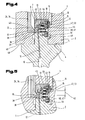
- FIG. 4 and FIG. 5 show in sectional view a further embodiment of a bending tool 1 according to the invention, used in a tool holder 2 of a press beam 3 of a bending machine, not shown, in particular press brake.
- the contact element 13, which is connected via a dash-dotted connection line 12 to a functional element 10 in the bending tool 1, is located in FIG Fig. 4 at rest 21 and thereby has a distance 27 (see Fig. 3 ) to the contact surface 14, whereby the connection between the functional element 10 and a power source or control device is interrupted on the bending machine.
- Such clamping elements 34 are part of the tool clamping for upper tools or lower tools on bending machines, especially press brakes and can be simultaneously used in a bending tool 1 according to the invention to move the contact element 13 from the rest position 21 in the contact position 23.
- the clamping element 34 in this case has a wedge element 35, which is oriented approximately to the right in the illustrated embodiment and can cooperate with a keyway 36 on the attachment extension 7 of the attachment portion 5 and thereby causes the clamping of the bending tool 1 in the tool holder 2.
- the actuating member 24 in the form of the clamping member 34 does not act directly on the contact element 13, but is on activation of the clamping member 34, so in a movement to the right, in the attachment extension 7 of the mounting portion 5 approximately horizontally adjustable mounted transmission element 37 here in the form a pressure bolt 38 is displaced together with a guide plate 39 to the right, whereby the contact element 13 connected to the guide plate 39 is also displaced to the right in the contact position 23 (see Fig. 5 ).
- the rest position of the contact element 13 with not activated clamping element 34 is effected in this embodiment by acting on the transmission element 37 to the left in the direction of the rest position 21 spring element 40 here in the form of a compression spring 41.
- the spring element 40 from 4 and FIG. 5 thus corresponds to the effect of the spring element 29 according to the Fig. 1 to 3 ,
- the pressure pin 38 and the contact element 13 to each other have a center distance 42, which even with small dimensions of the attachment extension 7 of the pressure pin 38 and the contact element 13 must not have extremely small dimensions and still have reasonably manageable dimensions.
- the guide plate 39 is oriented approximately at right angles to the mutually parallel adjustment of pressure pin 38 and contact element 13.
- the pressure pin 38 is cylindrical and guided approximately horizontally in a bore 43 in the attachment extension 7.
- the contact pin 38 is guided at its right, tapered end in a cover member 44 which closes the required for the pressure pin 38, the guide plate 39 and the contact element 13 movement spaces in the inner attachment extension 7 after assembly and further with an inserted in the cover member 44 electrically insulating guide sleeve 18, the contact element 13 additionally leads.
- the contact element 13 is divided into a firmly connected to the guide plate 39 sleeve member 45 and a coaxially guided therein pin member 46, wherein the axial force between the sleeve member 45 and pin member 46 by a in the sleeve part 45 arranged compression spring 47 is transmitted.
- the method for contacting the contact element 13 with the contact surface 14 thus proceeds in the following steps:
- the bending tool 1 is brought with the contact element 13 in the rest position to its intended position on the tool holder 2, in this embodiment, the attachment extension 7 inserted into the horritnut 6 until laterally adjoining the attachment extension 7 shoulder surfaces 48 on the side of the tool holder groove 6 subsequent contact surfaces 49 completely or at least approximately.
- This position can be achieved by means of a latching element formed on the fastening extension 7 50, which engages in a latching recess 51 in the tool holder groove 6, are secured, whereby even with not yet activated clamping device falling out of the bending tool 1 from the tool holder 2 is prevented.
- the tool clamping can be activated, whereby the clamping element 34, which simultaneously forms the actuator 24, is displaced to the right by means of an adjusting drive, whereby the wedge member 35 on the clamping element 34 in the keyway 36 on the attachment extension. 7 engages and thereby the bending tool 1 is pressed against the contact surfaces 49 of the tool holder 3.
- the pressure pin 38 positioned in the keyway 36 is shifted to the right, whereby the guide plate 39 connected thereto and the sleeve part 45 of the contact element 13 attached thereto are also displaced to the right.
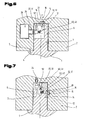
- Fig. 6 shows a further embodiment of a bending tool 1 according to the invention with the contact element 13 in rest position 21 in the intended position in the tool holder 2 used, but without activation of the contact by the actuator 24.
- the actuator 24 and contact element 13 arranged between transmission element 37 is in this embodiment by a Swivel lever 51 is formed, which is adjustably mounted by means of a pivot bearing 52 on the attachment portion 5, here the attachment extension 7 and the adjustment of the actuator 24 transmits to the contact element 13, whereby this starting from the illustrated rest position 21 in a contact surface 14 contacting, not shown here Contact position is spent and thereby again an electrical connection between the leading to the functional element 10 connecting line 12 and the power supply source or control device leading connection line 16 is produced.
- the approximately horizontal adjusting movement of the actuating member 24 is converted by means of the pivot lever 51 in an approximately vertical adjustment movement of the contact element 13, which is why This embodiment is particularly suitable when the actuator 24 and the contact surface 14 are not diametrically opposed to the receiving portion 4 of the tool holder 2.
- the rest position 21 of the contact element 13 with not activated actuator 24 is effected in this embodiment by acting on the transmission element 37 spring element 40, here in the form of a compression spring 41.
- Fig. 7 shows a further embodiment of a bending tool according to the invention 1 used in a tool holder 2 according to the invention, in which the actuator 24 in the Malawinut 6 is approximately vertically downwards and transmit its movement by means of a pivot lever 51 on the approximately horizontal in the attachment extension 7 adjustably mounted contact element 13 becomes.
- an elastic connecting element 53 is arranged between the transmission element 37 in the form of the pivot lever 51 and the contact element 13, whereby again the contact forces occurring between the contact portion 20 of the contact element 13 and the contact surface 14 can be limited.
- the rest position 21 of the contact element with not activated actuator 24 is characterized by a in Fig. 7 shown in dashed lines, acting on the transmission element 37 spring element 40, here in the form of a compression spring 41, causes.
- the adjusting drive 26 can be formed in this and in the other embodiments by, in particular by an electrically or fluidly driven actuator.
Landscapes
- Engineering & Computer Science (AREA)
- Mechanical Engineering (AREA)
- Bending Of Plates, Rods, And Pipes (AREA)
Applications Claiming Priority (1)
| Application Number | Priority Date | Filing Date | Title |
|---|---|---|---|
| AT16872008A AT507346B1 (de) | 2008-10-30 | 2008-10-30 | Biegewerkzeug und werkzeugaufnahme für eine biegemaschine |
Publications (3)
| Publication Number | Publication Date |
|---|---|
| EP2186579A2 true EP2186579A2 (fr) | 2010-05-19 |
| EP2186579A3 EP2186579A3 (fr) | 2012-09-12 |
| EP2186579B1 EP2186579B1 (fr) | 2016-06-15 |
Family
ID=42076985
Family Applications (1)
| Application Number | Title | Priority Date | Filing Date |
|---|---|---|---|
| EP09013145.9A Active EP2186579B1 (fr) | 2008-10-30 | 2009-10-19 | Outil de pliage et porte-outil pour une plieuse |
Country Status (3)
| Country | Link |
|---|---|
| EP (1) | EP2186579B1 (fr) |
| AT (1) | AT507346B1 (fr) |
| ES (1) | ES2590764T3 (fr) |
Cited By (1)
| Publication number | Priority date | Publication date | Assignee | Title |
|---|---|---|---|---|
| CN104338835A (zh) * | 2013-07-23 | 2015-02-11 | 西安永电电气有限责任公司 | 电极折弯冲压头与液压杆柱连接结构 |
Families Citing this family (3)
| Publication number | Priority date | Publication date | Assignee | Title |
|---|---|---|---|---|
| AT511591B1 (de) * | 2012-02-07 | 2013-01-15 | Trumpf Maschinen Austria Gmbh | Biegewerkzeug mit sicherheitseinrichtung |
| AT519002B1 (de) * | 2016-09-16 | 2018-03-15 | Trumpf Maschinen Austria Gmbh & Co Kg | Biegewerkzeug, insbesondere ein Oberwerkzeug oder einen Biegestempel, und ein Betriebswechselverfahren |
| DE102018216167A1 (de) * | 2018-09-21 | 2020-03-26 | Kipp Verpachtungen E.K. | Arretierbolzen mit Zustandsüberwachung |
Citations (1)
| Publication number | Priority date | Publication date | Assignee | Title |
|---|---|---|---|---|
| EP1600256A1 (fr) | 2004-05-24 | 2005-11-30 | Wila B.V. | Localisation et identification de outil dans un porte-outil |
Family Cites Families (3)
| Publication number | Priority date | Publication date | Assignee | Title |
|---|---|---|---|---|
| DE3830488A1 (de) * | 1988-09-08 | 1990-03-15 | Fastenrath Fasti Werk | Elektronisches werkzeugerkennungssystem fuer gesenkbiegepressen |
| JP4233944B2 (ja) * | 2003-08-29 | 2009-03-04 | 株式会社アマダ | 金型落下防止装置 |
| ATE497426T1 (de) * | 2006-06-07 | 2011-02-15 | Wila Bv | Werkzeug und werkzeughalter, mit einem datenaustauschsystem |
-
2008
- 2008-10-30 AT AT16872008A patent/AT507346B1/de not_active IP Right Cessation
-
2009
- 2009-10-19 ES ES09013145.9T patent/ES2590764T3/es active Active
- 2009-10-19 EP EP09013145.9A patent/EP2186579B1/fr active Active
Patent Citations (1)
| Publication number | Priority date | Publication date | Assignee | Title |
|---|---|---|---|---|
| EP1600256A1 (fr) | 2004-05-24 | 2005-11-30 | Wila B.V. | Localisation et identification de outil dans un porte-outil |
Cited By (1)
| Publication number | Priority date | Publication date | Assignee | Title |
|---|---|---|---|---|
| CN104338835A (zh) * | 2013-07-23 | 2015-02-11 | 西安永电电气有限责任公司 | 电极折弯冲压头与液压杆柱连接结构 |
Also Published As
| Publication number | Publication date |
|---|---|
| EP2186579B1 (fr) | 2016-06-15 |
| EP2186579A3 (fr) | 2012-09-12 |
| AT507346B1 (de) | 2010-07-15 |
| ES2590764T3 (es) | 2016-11-23 |
| AT507346A1 (de) | 2010-04-15 |
Similar Documents
| Publication | Publication Date | Title |
|---|---|---|
| EP2107650B1 (fr) | Pince de serrage dotée d'un positionneur | |
| AT514930B1 (de) | Hinteranschlageinheit für Biegemaschine | |
| EP3233323B1 (fr) | Outil de cintrage ayant un dispositif de mesure de décalage longitudinal | |
| WO2008011648A1 (fr) | Dispositif de butée pour presse à cintrer | |
| EP3541544B1 (fr) | Procédé de fonctionnement d'une machine de cintrage | |
| EP2208257A1 (fr) | Borne de raccordement à dispositif d'ouverture | |
| EP3600796B1 (fr) | Effecteur terminal à enveloppe protectrice coulissante pour l'usinage de pièces et système robotisé comprenant un effecteur terminal | |
| EP3010665B1 (fr) | Outil de pliage | |
| EP3397408B1 (fr) | Outil de formage | |
| EP2186579B1 (fr) | Outil de pliage et porte-outil pour une plieuse | |
| DE102009019805B4 (de) | Pneumatischer Lineargreifer | |
| DE102009020998A1 (de) | Niederhalter für eine Werkzeugmaschine | |
| DE10255617A1 (de) | Fassung für elektrische Bauteile | |
| WO2018033540A1 (fr) | Conducteur mince avec passages | |
| EP3095534B1 (fr) | Cintreuse | |
| EP3302842B1 (fr) | Procédé de réglage d'une section de formage d'un outil de cintrage | |
| AT517319A1 (de) | Biegewerkzeug für eine Biegepresse | |
| EP3041618A1 (fr) | Machine de pliage et procédé de pliage d'une pièce en tôle | |
| DE102023101100B4 (de) | Greifvorrichtung, Anspritzvorrichtung und Verfahren für biegeschlaffe Profile mit abgeschwächter Zwischenklemmung | |
| AT508224B1 (de) | Biegewerkzeug mit einem gleitbereich und verfahren zum betrieb eines solchen | |
| EP0419891B1 (fr) | Outil manuel pour terminer un câble plat dans un connecteur | |
| EP3512647B1 (fr) | Outil de cintrage, en particulier outil supérieur ou poinçon de cintrage, et procédé de changement de mode | |
| DE102016122422A1 (de) | Betätigungselement für einen Mikroschalter und Vorrichtung mit einem solchen zusätzlichen Betätigungselement | |
| EP2028003A2 (fr) | Dispositif de registre pour une presse d'impression de feuilles | |
| DE9107373U1 (de) | Meßstation für eine Schneidpresse |
Legal Events
| Date | Code | Title | Description |
|---|---|---|---|
| PUAI | Public reference made under article 153(3) epc to a published international application that has entered the european phase |
Free format text: ORIGINAL CODE: 0009012 |
|
| AK | Designated contracting states |
Kind code of ref document: A2 Designated state(s): AT BE BG CH CY CZ DE DK EE ES FI FR GB GR HR HU IE IS IT LI LT LU LV MC MK MT NL NO PL PT RO SE SI SK SM TR |
|
| AX | Request for extension of the european patent |
Extension state: AL BA RS |
|
| PUAL | Search report despatched |
Free format text: ORIGINAL CODE: 0009013 |
|
| AK | Designated contracting states |
Kind code of ref document: A3 Designated state(s): AT BE BG CH CY CZ DE DK EE ES FI FR GB GR HR HU IE IS IT LI LT LU LV MC MK MT NL NO PL PT RO SE SI SK SM TR |
|
| AX | Request for extension of the european patent |
Extension state: AL BA RS |
|
| RIC1 | Information provided on ipc code assigned before grant |
Ipc: B21D 5/02 20060101AFI20120807BHEP Ipc: B23Q 17/24 20060101ALI20120807BHEP Ipc: B23Q 3/155 20060101ALI20120807BHEP |
|
| 17P | Request for examination filed |
Effective date: 20130312 |
|
| GRAP | Despatch of communication of intention to grant a patent |
Free format text: ORIGINAL CODE: EPIDOSNIGR1 |
|
| RIC1 | Information provided on ipc code assigned before grant |
Ipc: B23Q 3/155 20060101ALI20151020BHEP Ipc: B23Q 17/24 20060101ALI20151020BHEP Ipc: B21D 5/02 20060101AFI20151020BHEP |
|
| INTG | Intention to grant announced |
Effective date: 20151124 |
|
| GRAP | Despatch of communication of intention to grant a patent |
Free format text: ORIGINAL CODE: EPIDOSNIGR1 |
|
| INTG | Intention to grant announced |
Effective date: 20160413 |
|
| GRAS | Grant fee paid |
Free format text: ORIGINAL CODE: EPIDOSNIGR3 |
|
| GRAA | (expected) grant |
Free format text: ORIGINAL CODE: 0009210 |
|
| AK | Designated contracting states |
Kind code of ref document: B1 Designated state(s): AT BE BG CH CY CZ DE DK EE ES FI FR GB GR HR HU IE IS IT LI LT LU LV MC MK MT NL NO PL PT RO SE SI SK SM TR |
|
| REG | Reference to a national code |
Ref country code: CH Ref legal event code: EP Ref country code: GB Ref legal event code: FG4D Free format text: NOT ENGLISH |
|
| REG | Reference to a national code |
Ref country code: IE Ref legal event code: FG4D Free format text: LANGUAGE OF EP DOCUMENT: GERMAN |
|
| REG | Reference to a national code |
Ref country code: AT Ref legal event code: REF Ref document number: 806216 Country of ref document: AT Kind code of ref document: T Effective date: 20160715 |
|
| REG | Reference to a national code |
Ref country code: DE Ref legal event code: R096 Ref document number: 502009012696 Country of ref document: DE |
|
| REG | Reference to a national code |
Ref country code: NL Ref legal event code: FP |
|
| REG | Reference to a national code |
Ref country code: LT Ref legal event code: MG4D Ref country code: FR Ref legal event code: PLFP Year of fee payment: 8 |
|
| PG25 | Lapsed in a contracting state [announced via postgrant information from national office to epo] |
Ref country code: LT Free format text: LAPSE BECAUSE OF FAILURE TO SUBMIT A TRANSLATION OF THE DESCRIPTION OR TO PAY THE FEE WITHIN THE PRESCRIBED TIME-LIMIT Effective date: 20160615 Ref country code: NO Free format text: LAPSE BECAUSE OF FAILURE TO SUBMIT A TRANSLATION OF THE DESCRIPTION OR TO PAY THE FEE WITHIN THE PRESCRIBED TIME-LIMIT Effective date: 20160915 |
|
| REG | Reference to a national code |
Ref country code: ES Ref legal event code: FG2A Ref document number: 2590764 Country of ref document: ES Kind code of ref document: T3 Effective date: 20161123 |
|
| PG25 | Lapsed in a contracting state [announced via postgrant information from national office to epo] |
Ref country code: HR Free format text: LAPSE BECAUSE OF FAILURE TO SUBMIT A TRANSLATION OF THE DESCRIPTION OR TO PAY THE FEE WITHIN THE PRESCRIBED TIME-LIMIT Effective date: 20160615 Ref country code: SE Free format text: LAPSE BECAUSE OF FAILURE TO SUBMIT A TRANSLATION OF THE DESCRIPTION OR TO PAY THE FEE WITHIN THE PRESCRIBED TIME-LIMIT Effective date: 20160615 Ref country code: GR Free format text: LAPSE BECAUSE OF FAILURE TO SUBMIT A TRANSLATION OF THE DESCRIPTION OR TO PAY THE FEE WITHIN THE PRESCRIBED TIME-LIMIT Effective date: 20160916 Ref country code: LV Free format text: LAPSE BECAUSE OF FAILURE TO SUBMIT A TRANSLATION OF THE DESCRIPTION OR TO PAY THE FEE WITHIN THE PRESCRIBED TIME-LIMIT Effective date: 20160615 |
|
| PG25 | Lapsed in a contracting state [announced via postgrant information from national office to epo] |
Ref country code: EE Free format text: LAPSE BECAUSE OF FAILURE TO SUBMIT A TRANSLATION OF THE DESCRIPTION OR TO PAY THE FEE WITHIN THE PRESCRIBED TIME-LIMIT Effective date: 20160615 Ref country code: IS Free format text: LAPSE BECAUSE OF FAILURE TO SUBMIT A TRANSLATION OF THE DESCRIPTION OR TO PAY THE FEE WITHIN THE PRESCRIBED TIME-LIMIT Effective date: 20161015 Ref country code: RO Free format text: LAPSE BECAUSE OF FAILURE TO SUBMIT A TRANSLATION OF THE DESCRIPTION OR TO PAY THE FEE WITHIN THE PRESCRIBED TIME-LIMIT Effective date: 20160615 |
|
| PGFP | Annual fee paid to national office [announced via postgrant information from national office to epo] |
Ref country code: FI Payment date: 20161013 Year of fee payment: 8 |
|
| PG25 | Lapsed in a contracting state [announced via postgrant information from national office to epo] |
Ref country code: SM Free format text: LAPSE BECAUSE OF FAILURE TO SUBMIT A TRANSLATION OF THE DESCRIPTION OR TO PAY THE FEE WITHIN THE PRESCRIBED TIME-LIMIT Effective date: 20160615 Ref country code: PL Free format text: LAPSE BECAUSE OF FAILURE TO SUBMIT A TRANSLATION OF THE DESCRIPTION OR TO PAY THE FEE WITHIN THE PRESCRIBED TIME-LIMIT Effective date: 20160615 Ref country code: PT Free format text: LAPSE BECAUSE OF FAILURE TO SUBMIT A TRANSLATION OF THE DESCRIPTION OR TO PAY THE FEE WITHIN THE PRESCRIBED TIME-LIMIT Effective date: 20161017 |
|
| PGFP | Annual fee paid to national office [announced via postgrant information from national office to epo] |
Ref country code: ES Payment date: 20161012 Year of fee payment: 8 |
|
| REG | Reference to a national code |
Ref country code: DE Ref legal event code: R097 Ref document number: 502009012696 Country of ref document: DE |
|
| PLBE | No opposition filed within time limit |
Free format text: ORIGINAL CODE: 0009261 |
|
| STAA | Information on the status of an ep patent application or granted ep patent |
Free format text: STATUS: NO OPPOSITION FILED WITHIN TIME LIMIT |
|
| 26N | No opposition filed |
Effective date: 20170316 |
|
| PG25 | Lapsed in a contracting state [announced via postgrant information from national office to epo] |
Ref country code: DK Free format text: LAPSE BECAUSE OF FAILURE TO SUBMIT A TRANSLATION OF THE DESCRIPTION OR TO PAY THE FEE WITHIN THE PRESCRIBED TIME-LIMIT Effective date: 20160615 |
|
| REG | Reference to a national code |
Ref country code: CH Ref legal event code: PL |
|
| GBPC | Gb: european patent ceased through non-payment of renewal fee |
Effective date: 20161019 |
|
| REG | Reference to a national code |
Ref country code: IE Ref legal event code: MM4A |
|
| PG25 | Lapsed in a contracting state [announced via postgrant information from national office to epo] |
Ref country code: CH Free format text: LAPSE BECAUSE OF NON-PAYMENT OF DUE FEES Effective date: 20161031 Ref country code: GB Free format text: LAPSE BECAUSE OF NON-PAYMENT OF DUE FEES Effective date: 20161019 Ref country code: LI Free format text: LAPSE BECAUSE OF NON-PAYMENT OF DUE FEES Effective date: 20161031 |
|
| PG25 | Lapsed in a contracting state [announced via postgrant information from national office to epo] |
Ref country code: SI Free format text: LAPSE BECAUSE OF FAILURE TO SUBMIT A TRANSLATION OF THE DESCRIPTION OR TO PAY THE FEE WITHIN THE PRESCRIBED TIME-LIMIT Effective date: 20160615 Ref country code: LU Free format text: LAPSE BECAUSE OF NON-PAYMENT OF DUE FEES Effective date: 20161019 |
|
| REG | Reference to a national code |
Ref country code: FR Ref legal event code: PLFP Year of fee payment: 9 |
|
| PG25 | Lapsed in a contracting state [announced via postgrant information from national office to epo] |
Ref country code: IE Free format text: LAPSE BECAUSE OF NON-PAYMENT OF DUE FEES Effective date: 20161019 |
|
| REG | Reference to a national code |
Ref country code: AT Ref legal event code: MM01 Ref document number: 806216 Country of ref document: AT Kind code of ref document: T Effective date: 20161019 |
|
| PG25 | Lapsed in a contracting state [announced via postgrant information from national office to epo] |
Ref country code: AT Free format text: LAPSE BECAUSE OF NON-PAYMENT OF DUE FEES Effective date: 20161019 |
|
| PG25 | Lapsed in a contracting state [announced via postgrant information from national office to epo] |
Ref country code: HU Free format text: LAPSE BECAUSE OF FAILURE TO SUBMIT A TRANSLATION OF THE DESCRIPTION OR TO PAY THE FEE WITHIN THE PRESCRIBED TIME-LIMIT; INVALID AB INITIO Effective date: 20091019 Ref country code: CY Free format text: LAPSE BECAUSE OF FAILURE TO SUBMIT A TRANSLATION OF THE DESCRIPTION OR TO PAY THE FEE WITHIN THE PRESCRIBED TIME-LIMIT Effective date: 20160615 |
|
| PG25 | Lapsed in a contracting state [announced via postgrant information from national office to epo] |
Ref country code: MT Free format text: LAPSE BECAUSE OF FAILURE TO SUBMIT A TRANSLATION OF THE DESCRIPTION OR TO PAY THE FEE WITHIN THE PRESCRIBED TIME-LIMIT Effective date: 20160615 Ref country code: MC Free format text: LAPSE BECAUSE OF FAILURE TO SUBMIT A TRANSLATION OF THE DESCRIPTION OR TO PAY THE FEE WITHIN THE PRESCRIBED TIME-LIMIT Effective date: 20160615 Ref country code: MK Free format text: LAPSE BECAUSE OF FAILURE TO SUBMIT A TRANSLATION OF THE DESCRIPTION OR TO PAY THE FEE WITHIN THE PRESCRIBED TIME-LIMIT Effective date: 20160615 |
|
| REG | Reference to a national code |
Ref country code: DE Ref legal event code: R082 Ref document number: 502009012696 Country of ref document: DE Representative=s name: ABP BURGER RECHTSANWALTSGESELLSCHAFT MBH, DE |
|
| PG25 | Lapsed in a contracting state [announced via postgrant information from national office to epo] |
Ref country code: FI Free format text: LAPSE BECAUSE OF NON-PAYMENT OF DUE FEES Effective date: 20171019 Ref country code: BG Free format text: LAPSE BECAUSE OF FAILURE TO SUBMIT A TRANSLATION OF THE DESCRIPTION OR TO PAY THE FEE WITHIN THE PRESCRIBED TIME-LIMIT Effective date: 20160615 |
|
| REG | Reference to a national code |
Ref country code: FR Ref legal event code: PLFP Year of fee payment: 10 |
|
| PGFP | Annual fee paid to national office [announced via postgrant information from national office to epo] |
Ref country code: SK Payment date: 20180907 Year of fee payment: 10 Ref country code: NL Payment date: 20180910 Year of fee payment: 10 Ref country code: CZ Payment date: 20180907 Year of fee payment: 10 Ref country code: TR Payment date: 20180910 Year of fee payment: 10 Ref country code: BE Payment date: 20180910 Year of fee payment: 10 |
|
| REG | Reference to a national code |
Ref country code: ES Ref legal event code: FD2A Effective date: 20181221 |
|
| PG25 | Lapsed in a contracting state [announced via postgrant information from national office to epo] |
Ref country code: ES Free format text: LAPSE BECAUSE OF NON-PAYMENT OF DUE FEES Effective date: 20171020 |
|
| REG | Reference to a national code |
Ref country code: NL Ref legal event code: MM Effective date: 20191101 |
|
| REG | Reference to a national code |
Ref country code: SK Ref legal event code: MM4A Ref document number: E 21984 Country of ref document: SK Effective date: 20191019 |
|
| PG25 | Lapsed in a contracting state [announced via postgrant information from national office to epo] |
Ref country code: CZ Free format text: LAPSE BECAUSE OF NON-PAYMENT OF DUE FEES Effective date: 20191019 |
|
| REG | Reference to a national code |
Ref country code: BE Ref legal event code: MM Effective date: 20191031 |
|
| PG25 | Lapsed in a contracting state [announced via postgrant information from national office to epo] |
Ref country code: NL Free format text: LAPSE BECAUSE OF NON-PAYMENT OF DUE FEES Effective date: 20191101 Ref country code: BE Free format text: LAPSE BECAUSE OF NON-PAYMENT OF DUE FEES Effective date: 20191031 Ref country code: SK Free format text: LAPSE BECAUSE OF NON-PAYMENT OF DUE FEES Effective date: 20191019 |
|
| PG25 | Lapsed in a contracting state [announced via postgrant information from national office to epo] |
Ref country code: TR Free format text: LAPSE BECAUSE OF FAILURE TO SUBMIT A TRANSLATION OF THE DESCRIPTION OR TO PAY THE FEE WITHIN THE PRESCRIBED TIME-LIMIT Effective date: 20160615 |
|
| P01 | Opt-out of the competence of the unified patent court (upc) registered |
Effective date: 20230524 |
|
| PGFP | Annual fee paid to national office [announced via postgrant information from national office to epo] |
Ref country code: IT Payment date: 20240913 Year of fee payment: 16 |
|
| PGFP | Annual fee paid to national office [announced via postgrant information from national office to epo] |
Ref country code: DE Payment date: 20241016 Year of fee payment: 16 |
|
| PGFP | Annual fee paid to national office [announced via postgrant information from national office to epo] |
Ref country code: FR Payment date: 20241025 Year of fee payment: 16 |
|
| REG | Reference to a national code |
Ref country code: DE Ref legal event code: R119 Ref document number: 502009012696 Country of ref document: DE |
|
| PG25 | Lapsed in a contracting state [announced via postgrant information from national office to epo] |
Ref country code: DE Free format text: LAPSE BECAUSE OF NON-PAYMENT OF DUE FEES Effective date: 20260501 |
|
| PG25 | Lapsed in a contracting state [announced via postgrant information from national office to epo] |
Ref country code: FR Free format text: LAPSE BECAUSE OF NON-PAYMENT OF DUE FEES Effective date: 20251031 |