EP2186706A1 - Vorrichtung zum Erkennen von Anomalien für eine Überwachungsanlage eines Schienenfahrzeugs sowie entsprechende Anlage und entsprechendes Verfahren - Google Patents
Vorrichtung zum Erkennen von Anomalien für eine Überwachungsanlage eines Schienenfahrzeugs sowie entsprechende Anlage und entsprechendes Verfahren Download PDFInfo
- Publication number
- EP2186706A1 EP2186706A1 EP09175281A EP09175281A EP2186706A1 EP 2186706 A1 EP2186706 A1 EP 2186706A1 EP 09175281 A EP09175281 A EP 09175281A EP 09175281 A EP09175281 A EP 09175281A EP 2186706 A1 EP2186706 A1 EP 2186706A1
- Authority
- EP
- European Patent Office
- Prior art keywords
- cable
- state
- impedance
- phase
- beacon
- Prior art date
- Legal status (The legal status is an assumption and is not a legal conclusion. Google has not performed a legal analysis and makes no representation as to the accuracy of the status listed.)
- Granted
Links
Images

Classifications
-
- B—PERFORMING OPERATIONS; TRANSPORTING
- B61—RAILWAYS
- B61L—GUIDING RAILWAY TRAFFIC; ENSURING THE SAFETY OF RAILWAY TRAFFIC
- B61L3/00—Devices along the route for controlling devices on the vehicle or train, e.g. to release brake or to operate a warning signal
- B61L3/02—Devices along the route for controlling devices on the vehicle or train, e.g. to release brake or to operate a warning signal at selected places along the route, e.g. intermittent control simultaneous mechanical and electrical control
- B61L3/08—Devices along the route for controlling devices on the vehicle or train, e.g. to release brake or to operate a warning signal at selected places along the route, e.g. intermittent control simultaneous mechanical and electrical control controlling electrically
- B61L3/12—Devices along the route for controlling devices on the vehicle or train, e.g. to release brake or to operate a warning signal at selected places along the route, e.g. intermittent control simultaneous mechanical and electrical control controlling electrically using magnetic or electrostatic induction; using radio waves
- B61L3/121—Devices along the route for controlling devices on the vehicle or train, e.g. to release brake or to operate a warning signal at selected places along the route, e.g. intermittent control simultaneous mechanical and electrical control controlling electrically using magnetic or electrostatic induction; using radio waves using magnetic induction
-
- G—PHYSICS
- G01—MEASURING; TESTING
- G01R—MEASURING ELECTRIC VARIABLES; MEASURING MAGNETIC VARIABLES
- G01R31/00—Arrangements for testing electric properties; Arrangements for locating electric faults; Arrangements for electrical testing characterised by what is being tested not provided for elsewhere
- G01R31/08—Locating faults in cables, transmission lines, or networks
- G01R31/081—Locating faults in cables, transmission lines, or networks according to type of conductors
- G01R31/083—Locating faults in cables, transmission lines, or networks according to type of conductors in cables, e.g. underground
-
- G—PHYSICS
- G01—MEASURING; TESTING
- G01R—MEASURING ELECTRIC VARIABLES; MEASURING MAGNETIC VARIABLES
- G01R31/00—Arrangements for testing electric properties; Arrangements for locating electric faults; Arrangements for electrical testing characterised by what is being tested not provided for elsewhere
- G01R31/50—Testing of electric apparatus, lines, cables or components for short-circuits, continuity, leakage current or incorrect line connections
- G01R31/52—Testing for short-circuits, leakage current or ground faults
-
- G—PHYSICS
- G01—MEASURING; TESTING
- G01R—MEASURING ELECTRIC VARIABLES; MEASURING MAGNETIC VARIABLES
- G01R31/00—Arrangements for testing electric properties; Arrangements for locating electric faults; Arrangements for electrical testing characterised by what is being tested not provided for elsewhere
- G01R31/50—Testing of electric apparatus, lines, cables or components for short-circuits, continuity, leakage current or incorrect line connections
- G01R31/54—Testing for continuity
-
- G—PHYSICS
- G01—MEASURING; TESTING
- G01R—MEASURING ELECTRIC VARIABLES; MEASURING MAGNETIC VARIABLES
- G01R31/00—Arrangements for testing electric properties; Arrangements for locating electric faults; Arrangements for electrical testing characterised by what is being tested not provided for elsewhere
- G01R31/50—Testing of electric apparatus, lines, cables or components for short-circuits, continuity, leakage current or incorrect line connections
- G01R31/58—Testing of lines, cables or conductors
-
- G—PHYSICS
- G01—MEASURING; TESTING
- G01R—MEASURING ELECTRIC VARIABLES; MEASURING MAGNETIC VARIABLES
- G01R31/00—Arrangements for testing electric properties; Arrangements for locating electric faults; Arrangements for electrical testing characterised by what is being tested not provided for elsewhere
- G01R31/005—Testing of electric installations on transport means
- G01R31/008—Testing of electric installations on transport means on air- or spacecraft, railway rolling stock or sea-going vessels
Definitions
- the present invention relates to the field of anomaly detection devices for ground equipment of a railway vehicle supervision facility, such as a train or a subway.
- ERTMS / ETCS aims to supervise the driving of a train throughout its course. For this, the train receives information on the signaling and / or the topology of the section of track on which it engages, in order to be able to optimize, at each moment, its speed. The regulation of the speed of the train is done automatically by supervising the actions of the driver and by taking the place of him in certain situations.
- the ERTMS / ETCS standard provides equipment on board the train and equipment on the ground.
- An on-board equipment includes an antenna adapted to receive short-range radio signals emitted by ground equipment, and a computing and control unit connected to the antenna, able to process the received radio signal and to actuate it in a suitable manner. different parts of the train and, in particular, its braking system.
- a ground equipment comprises an encoder or LEU, the acronym for the word “Line Side Electronic Unit” for “lateral electronic unit”, capable of being controlled from a remote control station, and at least one beacon arranged on the track, for example to the right of signaling equipment or at the beginning of a section of track, and connected to an output of the LEU by means of a communication cable.
- LEU encoder or LEU
- a particular LEU can be connected up to four beacons by four communication cables.
- a particular LEU is programmed with the topological parameters of the section of lane that a beacon to which it is connected must equip. These topological parameters include, for example, the slope of the track section, the existence of a turn, a maximum safety speed, etc. It is able to generate a telegram comprising these topological parameters and to transmit it to the corresponding beacon according to a protocol defined in the ERTMS / ETCS standard.
- the beacon connected to the LEU transmits a radio signal including the received telegram.
- the communication cable between the LEU and a beacon can reach 5000 m.
- Such a cable is placed near the track, often buried in a closed trough running along the track.
- the correct operation of the communication cable can be impaired by improper installation, significant thermal variations, vibrations during the passage of a train, an accident when, for example, workers are working on the track, malice, incorrect connection two segments of the cable, etc.
- the invention therefore aims to provide a device for detecting an anomaly along a communication cable connecting a LEU and a beacon, and in particular an anomaly of the open circuit or short circuit type.
- the invention relates to an anomaly detection device along a communication cable connecting an encoder and a beacon of ground equipment of a rail vehicle supervision installation, comprising: measurement means impedance capable of measuring, at a predetermined frequency, the phase and the module of the impedance of the cable during the transmission of an electrical communication signal generated by the encoder to the beacon; and cable condition determining means adapted to compare the measured phase and the modulus with reference values of the phase and the modulus of the impedance of the cable so as to determine a state of the cable among a state of operation. normal, a short circuit state and an open circuit state.
- the invention relates to equipment on the ground of a rail vehicle supervision installation, comprising an encoder, a beacon disposed on the track and a communication cable connecting the encoder and the beacon.
- the equipment includes an abnormality detection device such as the one presented above.
- the abnormality detecting device (12) is disposed at the interface between the encoder (3) and the communication cable (10).
- the invention also relates to a method for detecting an anomaly of the short-circuit or open-circuit type along a communication cable connecting an encoder and a beacon of equipment on the ground of a supervision installation.
- a railway vehicle implementing an abnormality detection device such as that described above.
- the method comprises the steps of measuring, at a predetermined frequency, the phase and the module of the impedance of the cable during the transmission of an electrical communication signal generated by the encoder to the beacon; and comparing the phase and the module measured with reference values of the phase and the module of the impedance of the cable so as to determine a condition of the cable among a normal operating state, a short-circuit state and a state of open circuit.
- the method includes a step of calculating the position of the fault along the cable.
- the ground equipment 1 of an installation complying with the ERTMS / ETCS standard for the supervision of a train running along a track comprises an encoder or LEU 3, at least one beacon 5 arranged between the two rails of the track, and a communication cable 10 connecting the LEU 3 and the tag 5.
- LEU 3 an encoder or LEU 3
- a communication cable 10 connecting the LEU 3 and the tag 5.
- a same LEU 3 is connected to four beacons 5 to 8 by as many communication cables 10 to 13.
- the cable 10 allows the downward communication of the LEU 3 to the beacon 5.
- the ERTMS / ETCS standard defines both a communication protocol at the physical layer level and a communication protocol at the data exchange layer level.
- the communication protocol at the physical layer level is more particularly defined in specifications 036 and 085 of the ERTMS / ETCS standard.
- the ground equipment 1 also comprises a detection device 12 able to detect, in real time, the presence and the position of an anomaly along the communication cable 10.
- the detection device 12 measures the impedance of the cable 10 while it is coupled to the beacon 5, then detects an anomaly according to the measured impedance.
- Such an anomaly is of the short circuit or open circuit type.
- the device 12 takes the form of an electronic card.
- the detection device 12 is arranged as an interface between the LEU 3, on the one hand, and the communication cable 10 and the beacon 5, on the other hand.
- the input of the device 12 is connected at the output of the LEU 3 and the input of the cable 10 is connected at the output of the device 12.
- the input of the device 12 takes the connectivity of a communication cable as defined in the ERTMS / ETCS standard, and the output of the device 12 takes the output connector of a LEU, as specified by the ERTMS / ETCS.
- the device 12 comprises means for measuring the impedance and means for determining the state of the cable from the measurement of the impedance produced by the impedance measuring means.
- the device 12 is able to measure the impedance of the cable 10, not by reflectometry of an electrical pulse signal applied at the input of the cable, but from the electrical communication signals applied by the LEU 3 at the input of the cable 10 during the normal operation of the equipment 1.
- the measurement of the impedance is completely transparent vis-à-vis the communication between the LEU 3 and the tag 5, the measurement having virtually no impact on the characteristics of the link between the LEU 3 and the beacon 5.
- the impedance measuring means are able to measure the instantaneous impedance of the cable 10 when an electrical signal, corresponding to the superposition of the signals C1 and C6, traverses the cable 10. For this, the measuring means of the impedance measure, at each moment, the frequency F6, the phase and the amplitude of the impedance of the cable 10.
- the impedance measuring means comprise means for measuring the voltage 14 and the intensity measuring means 16.
- a high impedance isolation transformer 20 is used for measuring the voltage of the current flowing in the cable 10 ( figure 2 ).
- the measurement of the voltage does not affect the signal emitted by the LEU 3 along the cable 10 provided that the load resistor 22 placed on the secondary side of the isolation transformer 20 is chosen so that it is very high.
- the isolation transformer 20 has a ratio of 1 to primary to 1 to secondary.
- the measurement signal of the output voltage of the means 16 has undergone a first filtering.
- the measurement signal of the voltage has a level of 5 Vppmax at the output of the voltage measuring means 14.
- a low impedance input intensity transformer 30 is used.
- the primary of this intensity transformer 30 is constituted by the cable 10.
- the intensity transformer 30 has a ratio of 1 to 10 primary to the secondary. It has an equivalent input resistance of 65 m ⁇ . It is seen from the LEU 3 as a simple increase in the length of the cable 10 by a few meters, which does not interfere with the communication between the LEU 3 and the beacon 5.
- a resistor 32 of about 200 ⁇ in the secondary of the intensity transformer 30 an intensity measurement signal is obtained at the output of the means 30 which is a voltage signal whose amplitude is, for example, 20 mV per mA at the primary when the numerical values of the electronic components indicated on the figure 3 .
- the signal C6 at a frequency F6 of 8.82 kHz with a peak to peak voltage substantially equal to 19 Vppmin.
- the impedance measuring means therefore comprise filtering means 34 capable of filtering the measurement signals of the voltage and of the intensity so as to reject the components disturbing the component associated with the signal C6, and in particular the associated component. at signal C1.
- the signal C1 having a power spectrum ranging between 1 ⁇ 2.F1 and 2. F1, the cutoff frequency of the filtering means 34 must be chosen less than 1 ⁇ 2.F1, that is to say less than 282 kHz. This cutoff frequency is chosen three octaves below 1 ⁇ 2.F1 frequency to best reject the component associated with signal C1.
- the cutoff frequency of the means 34 is 35 kHz.
- the filtering of the voltage measurement signal involves a first filter stage at the isolation transformer 20 as mentioned above. Then, the voltage measurement signal passes through a second filter stage having a second order filter to produce a filtered voltage measurement signal.
- the intensity measurement signal is filtered by two second-order filters placed in series with each other.
- the first filter returns the intensity measurement signal to a level of 5 Vppmax and the second filter is equivalent to the second stage of the filtering means of the voltage measurement signal.
- a filtered intensity measurement signal is produced at the output of the means 34.
- the filtered measurement signals are applied at the input of a microcontroller 40 via an adaptation means 42 which will be described hereinafter.
- the microcontroller 40 calculates the module and the phase of the impedance of the cable 10.
- the ratio of the maximum value of the filtered signal for measuring the voltage to the maximum value of the filtered intensity measurement signal makes it possible to determine the modulus of the impedance of the communication cable 10.
- each input of the microcontroller is associated with a counter of cycles of clock.
- the filtered voltage measurement signal is canceled, the associated voltage counter is reset.
- the value of the voltage counter gives a measurement of the current value. phase shift between the two measurement signals and, consequently, the phase of the impedance of the cable 10.
- these are amplified by the adaptation means 42.
- they are are amplified to saturation to obtain signals with steep slopes.
- This adaptation step is performed by passing filtered measurement signals in comparators. The outputs of these comparators are applied to different inputs of the microcontroller 40.
- the measurements of the modulus and phase of the impedance are averaged over several successive periods to obtain a more precise measurement of the complex impedance.
- the device 12 will detect this impedance variation, but will not take it into consideration in determining the state of the cable 10 because it does not last long enough.
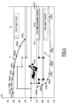
- the microcontroller 40 comprises a read-only memory in which is stored a calibration map 50 delimiting different domains in the complex plane of the values of the impedance of the cable 10.
- mapping 50 is represented at figure 4 . It is obtained at the end of a calibration step of a reference communication cable of the same type as the cable 10.
- the value of the impedance of the reference cable placed in a normal operating state is measured.
- the value of the measured impedance is plotted on the map 50.
- the value of the impedance of the reference cable placed in a state of short circuit is measured.
- the value of the impedance is measured for different positions of the short circuit along the reference cable, for example positions spaced from each other by a step of 500 m.
- the succession of values of the impedance thus measured are reported on the map 50.
- a curve A is obtained by extrapolation of a curve passing through the different calibration points in short circuit.
- the value of the impedance of the reference cable placed in an open circuit state is measured.
- the value of the impedance is measured for different positions of the open circuit along the reference cable, for example for positions spaced from each other by a step of 500 m.
- the succession of values of the impedance in open circuit are plotted on the map 50.
- a curve B is obtained by extrapolation of a curve passing through the different calibration points in open circuit.
- curves A and B do not overlap. They are distant from each other, as well as values of the impedance of the cable connected to the beacon, in the state in normal operation.
- each domain corresponds to a state of the cable: normal operating state, short circuit state and open circuit state.
- the position of a value of the impedance on the curve A, or the curve B makes it possible to determine the position of the associated anomaly along the cable.
- the microcontroller 40 in comparison with the map 50, assigns to the measured impedance a particular domain and associated with the instantaneous state of the cable the state corresponding to this domain.
- the microcontroller 40 assigns to a dated state parameter the value +1 when the state of the cable is short-circuited, the value 0 when the state of the cable is in operation, and the value -1 when the state of the cable is in open circuit.
- the microcontroller 40 determines the position of the anomaly along the cable. For this, it places the value of the impedance measured on the curve A, or the curve B, and, for example by a barycentric method between the nearest calibration points, calculates the position of the anomaly along the cable 10. The position can be calculated with a fairly good accuracy, of the order of 250 m. The calculated position of the anomaly is saved in a distance parameter associated with the state parameter.
- the device 12 also comprises an electrical disconnection means 60.
- the disconnecting means 60 comprises an LED 62 connected to an output terminal of the microcontroller 40 and controlled by the value of the state parameter.
- the LED 62 closes a switch with MOSFETs 64 leading to the short-circuiting of the corresponding output of the LEU 3.
- the LEU 3 being protected against the setting short circuit of one of its outputs, it stops the transmission of the electrical communication signal on the short-circuited output and simultaneously transmits a report towards the remote control station indicating the break of the link with the beacon connected to the output considered.
- the tag 5 is no longer connected to the LEU 3 it sends a radio signal with a default telegram defined in the standard ERTMS / ETCS. A train passing over the beacon and receiving such a default telegram will have its optimized speed reduced.
- the disconnection means 60 comprises a surge suppressor 66 so as to protect the LEU 3 from any overvoltages.
- the device 12 also comprises display means 70 making it possible to display, among other things, the state of the various cables 10 to 13.
- This is for example a table consisting of a row of four green LEDs and a a row of four red LEDs.
- the states of the various LEDs allow the operator to know the state of the four cables 10 to 13 according to the following Table I: (Table I) State Red LEDs Green LEDs No power supply All extinct All extinct ith connected Tag i th LED lit i th LED lit Open circuit on the i th cable i th LED lit i th LED extinguished Short circuit on the i th cable i th LED extinguished i th LED lit i th entry is not connected to LEU i th LED flashes i th LED flashes in phase i th output of LEU inhibited i th LED flashes i th LED Flashing in phase opposition i th output of the inhibited detection device i th LED flashes quickly i
- the microcontroller 40 is able to store data corresponding to the states of the cable 10 and the distance parameters associated with each time an anomaly has been detected.
- the device 12 comprises an input / output interface 80, for example of the RS232 type, allowing the communication between a user terminal 82 and the microcontroller 40 so as to transfer the data in the form of a history for an analysis out of online or in real time for remote alarm management.
- the real-time software analysis of these data may possibly dispense with the electrical disconnection means 60.
- the device 12 comprises a power supply 90 for supplying the electronic card with a DC voltage of 5 V.
- the present anomaly detection device allows the detection of an anomaly, almost at the moment it occurs, specifies the nature and gives a location along the cable affected.
- the effects of this anomaly on the train traffic along the track can be immediately taken into account and a team can quickly intervene on the indicated site to restore the normal operation of the encoder / beacon link.
- Such a device can also be used during the deployment of the ERTMS / ETCS installation and more particularly in the test phase of this installation.
- such a device can find applications not only in level 1 of the ETCS standard, but also in level 2 of this standard whereas the beacons arranged on the track are used only as backup means in case breaking the GPS communication.
Landscapes
- Physics & Mathematics (AREA)
- General Physics & Mathematics (AREA)
- Engineering & Computer Science (AREA)
- Mechanical Engineering (AREA)
- Train Traffic Observation, Control, And Security (AREA)
- Electric Propulsion And Braking For Vehicles (AREA)
- Alarm Systems (AREA)
- Radar Systems Or Details Thereof (AREA)
Priority Applications (1)
| Application Number | Priority Date | Filing Date | Title |
|---|---|---|---|
| PL09175281T PL2186706T3 (pl) | 2008-11-12 | 2009-11-06 | Urządzenie do wykrywania anomalii w instalacji do nadzoru pojazdu szynowego, instalacja oraz powiązany sposób |
Applications Claiming Priority (1)
| Application Number | Priority Date | Filing Date | Title |
|---|---|---|---|
| FR0857661A FR2938229B1 (fr) | 2008-11-12 | 2008-11-12 | Dispositif de detection d'anomalie pour une installation de supervision d'un vehicule ferroviaire, installation et procede associes |
Publications (2)
| Publication Number | Publication Date |
|---|---|
| EP2186706A1 true EP2186706A1 (de) | 2010-05-19 |
| EP2186706B1 EP2186706B1 (de) | 2012-04-18 |
Family
ID=40679639
Family Applications (1)
| Application Number | Title | Priority Date | Filing Date |
|---|---|---|---|
| EP09175281A Not-in-force EP2186706B1 (de) | 2008-11-12 | 2009-11-06 | Vorrichtung zum Erkennen von Anomalien für eine Überwachungsanlage eines Schienenfahrzeugs sowie entsprechende Anlage und entsprechendes Verfahren |
Country Status (6)
| Country | Link |
|---|---|
| EP (1) | EP2186706B1 (de) |
| CN (1) | CN101738569B (de) |
| AT (1) | ATE553977T1 (de) |
| FR (1) | FR2938229B1 (de) |
| PL (1) | PL2186706T3 (de) |
| RU (1) | RU2509317C2 (de) |
Cited By (9)
| Publication number | Priority date | Publication date | Assignee | Title |
|---|---|---|---|---|
| CN103675552A (zh) * | 2013-12-23 | 2014-03-26 | 北京交大思诺科技有限公司 | 机车信号设备抗干扰能力的测试系统及方法 |
| CN105046975A (zh) * | 2015-08-20 | 2015-11-11 | 河北上元工控技术有限公司 | 一种高速公路全程监控节点检测电路 |
| CN109061361A (zh) * | 2018-07-18 | 2018-12-21 | 西南交通大学 | Zpw-2000补偿电容开路故障预警方法 |
| CN109884450A (zh) * | 2019-03-19 | 2019-06-14 | 卡斯柯信号有限公司 | 一种检测应答器电缆状态的装置及方法 |
| EP3699619A1 (de) * | 2019-02-20 | 2020-08-26 | Tecnikabel S.p.A. | Automatisches überwachungssystem der verdrahtungsintegrität mit verbesserten funktionen |
| WO2023036708A1 (fr) * | 2021-09-10 | 2023-03-16 | Vitesco Technologies GmbH | Calculateur de controle moteur |
| KR20240021792A (ko) * | 2021-06-16 | 2024-02-19 | 이알티엠에스 솔루션즈 | 철도 환경에서 etcs 선로변 전기 유닛과 궤도변 발리스 사이의 전기 신호의 모니터링 |
| EP4324716A1 (de) * | 2022-08-16 | 2024-02-21 | Siemens Mobility AG | Verfahren und einrichtung zur überwachung der verbindung zu einer gleisseitig angeordneten balise |
| EP4431955A1 (de) * | 2023-03-14 | 2024-09-18 | Supergrid Institute | Verfahren zur erkennung eines fehlers auf einem elektrischen leistungsabschnitt eines eisenbahnnetzes und vorrichtung dafür |
Families Citing this family (17)
| Publication number | Priority date | Publication date | Assignee | Title |
|---|---|---|---|---|
| CN102565621A (zh) * | 2012-03-02 | 2012-07-11 | 北京和利时系统工程有限公司 | 一种应答器电缆状态的检测装置及检测方法 |
| CN103095384A (zh) * | 2012-12-25 | 2013-05-08 | 北京铁路信号有限公司 | 一种地面电子单元leu的闭环测试方法及系统 |
| CN103278706B (zh) * | 2013-04-22 | 2016-12-28 | 深圳市速普瑞科技有限公司 | 一种用于轨道交通的智能测试系统及方法 |
| CN104297609B (zh) * | 2013-07-19 | 2017-05-24 | 瑞昱半导体股份有限公司 | 判断第一接脚与第二接脚连接状态的检测电路与检测方法 |
| US20160121736A1 (en) * | 2014-10-31 | 2016-05-05 | Schneider Electric USA, Inc. | Evse shorted cable protection method |
| DE102017212730A1 (de) * | 2017-07-25 | 2019-01-31 | Siemens Aktiengesellschaft | Verfahren und Einrichtung zur Fehlerortung entlang einer Energieversorgungsstrecke bei Gleichstromsystemen |
| DE102017122684A1 (de) * | 2017-09-29 | 2019-04-04 | Lisa Dräxlmaier GmbH | Prüfvorrichtung und prüfverfahren zum prüfen eines datenkabels für ein kraftfharzeug mittels konstantstromquelle |
| CN108132433B (zh) * | 2017-11-13 | 2020-02-14 | 北京全路通信信号研究设计院集团有限公司 | 一种leu监测板信号提取电路 |
| CN110806549B (zh) * | 2018-08-03 | 2025-08-01 | 中车大连电力牵引研发中心有限公司 | 线缆检测系统及方法 |
| CN109080662A (zh) * | 2018-08-23 | 2018-12-25 | 广州地铁集团有限公司 | 一种道岔控制器监测系统及监测方法 |
| CN110928274B (zh) * | 2019-12-09 | 2021-03-02 | 通号(北京)轨道工业集团有限公司轨道交通技术研究院 | 一种leu设备的测试系统 |
| CN112130029B (zh) * | 2020-10-10 | 2024-03-01 | 中车青岛四方机车车辆股份有限公司 | 一种列车网络故障检测工装及检测方法 |
| CN112653088B (zh) * | 2020-12-17 | 2022-08-30 | 卡斯柯信号有限公司 | 一种地面电子单元的应答器电缆自适应短路保护方法 |
| CN113325247A (zh) * | 2021-01-12 | 2021-08-31 | 山西润泽丰科技股份有限公司 | 一种leu测试台系统及其测试方法及其校准方法 |
| CN113409556A (zh) * | 2021-06-10 | 2021-09-17 | 通号(北京)轨道工业集团有限公司轨道交通技术研究院 | 一种leu监测预警方法及系统 |
| CN114006632B (zh) * | 2021-10-29 | 2023-05-23 | 北京铁路信号有限公司 | 一种地面电子单元leu的测试方法及系统 |
| CN115656709A (zh) * | 2022-10-19 | 2023-01-31 | 北京和利时系统工程有限公司 | 电缆故障检测方法及装置 |
Citations (5)
| Publication number | Priority date | Publication date | Assignee | Title |
|---|---|---|---|---|
| DE4038267A1 (de) * | 1989-12-04 | 1991-06-06 | Siemens Ag | Einrichtung zur punktweisen daten- und energieuebertragung |
| DE19708518A1 (de) * | 1997-03-03 | 1998-10-01 | Signal Concept Gmbh | Verfahren und Vorrichtung zum Auffinden einer Defektstelle in einer Leiterschleife |
| WO2001013132A1 (en) * | 1999-08-11 | 2001-02-22 | Aegis Pty Ltd | Fault location device and method |
| US6980007B1 (en) * | 2002-06-07 | 2005-12-27 | Marvell International Ltd. | Cable tester with insertion loss and return loss estimators |
| EP1661784A1 (de) * | 2004-11-25 | 2006-05-31 | Siemens Schweiz AG | Verfahren und System zur Überprüfung der Funktion einer Datenübertragungseinheit zur Steuerung eines fahrenden Objektes |
Family Cites Families (7)
| Publication number | Priority date | Publication date | Assignee | Title |
|---|---|---|---|---|
| SU1725169A1 (ru) * | 1990-02-28 | 1992-04-07 | Московский Горный Институт | Устройство дл обнаружени участка повреждени изол ции в кабел х |
| DE4125446A1 (de) * | 1991-08-01 | 1993-02-04 | Uwe Dipl Ing Behmann | Verfahren und einrichtung zur elektrischen kurzschlusspruefung und -ortung fuer leitungen, insbesondere fuer fahrleitungen elektrischer bahnen |
| JP2001358617A (ja) * | 2000-06-13 | 2001-12-26 | Telecommunication Advancement Organization Of Japan | 通信ケーブル網の不良検出方法および不良監視装置 |
| CN2436941Y (zh) * | 2000-07-27 | 2001-06-27 | 李坤 | 电信线路故障检测仪 |
| CN1270929C (zh) * | 2003-10-14 | 2006-08-23 | 北京交通大学 | 轨道电路一次参数高精度快速地面测试方法 |
| US7705607B2 (en) * | 2006-08-25 | 2010-04-27 | Instrument Manufacturing Company | Diagnostic methods for electrical cables utilizing axial tomography |
| RU72333U1 (ru) * | 2007-11-26 | 2008-04-10 | Аркадий Яковлевич Раскин | Устройство для контроля состояния телефонных кабелей определения места их обрыва |
-
2008
- 2008-11-12 FR FR0857661A patent/FR2938229B1/fr not_active Expired - Fee Related
- 2008-11-18 CN CN200810190977.9A patent/CN101738569B/zh active Active
-
2009
- 2009-11-06 AT AT09175281T patent/ATE553977T1/de active
- 2009-11-06 PL PL09175281T patent/PL2186706T3/pl unknown
- 2009-11-06 EP EP09175281A patent/EP2186706B1/de not_active Not-in-force
- 2009-11-11 RU RU2009141756/28A patent/RU2509317C2/ru active
Patent Citations (5)
| Publication number | Priority date | Publication date | Assignee | Title |
|---|---|---|---|---|
| DE4038267A1 (de) * | 1989-12-04 | 1991-06-06 | Siemens Ag | Einrichtung zur punktweisen daten- und energieuebertragung |
| DE19708518A1 (de) * | 1997-03-03 | 1998-10-01 | Signal Concept Gmbh | Verfahren und Vorrichtung zum Auffinden einer Defektstelle in einer Leiterschleife |
| WO2001013132A1 (en) * | 1999-08-11 | 2001-02-22 | Aegis Pty Ltd | Fault location device and method |
| US6980007B1 (en) * | 2002-06-07 | 2005-12-27 | Marvell International Ltd. | Cable tester with insertion loss and return loss estimators |
| EP1661784A1 (de) * | 2004-11-25 | 2006-05-31 | Siemens Schweiz AG | Verfahren und System zur Überprüfung der Funktion einer Datenübertragungseinheit zur Steuerung eines fahrenden Objektes |
Non-Patent Citations (1)
| Title |
|---|
| RHEIN D ET AL: "ETCS Level 1 Lineside System - The Alcatel Solution", SIGNAL + DRAHT, TELZLAFF VERLAG GMBH. DARMSTADT, DE, vol. 94, 1 September 2002 (2002-09-01), pages 58 - 65, XP002276768, ISSN: 0037-4997 * |
Cited By (16)
| Publication number | Priority date | Publication date | Assignee | Title |
|---|---|---|---|---|
| CN103675552B (zh) * | 2013-12-23 | 2016-09-14 | 北京交大思诺科技股份有限公司 | 机车信号设备抗干扰能力的测试系统及方法 |
| CN103675552A (zh) * | 2013-12-23 | 2014-03-26 | 北京交大思诺科技有限公司 | 机车信号设备抗干扰能力的测试系统及方法 |
| CN105046975A (zh) * | 2015-08-20 | 2015-11-11 | 河北上元工控技术有限公司 | 一种高速公路全程监控节点检测电路 |
| CN105046975B (zh) * | 2015-08-20 | 2017-08-25 | 河北上元智能科技股份有限公司 | 一种高速公路全程监控节点检测电路 |
| CN109061361A (zh) * | 2018-07-18 | 2018-12-21 | 西南交通大学 | Zpw-2000补偿电容开路故障预警方法 |
| EP3699619A1 (de) * | 2019-02-20 | 2020-08-26 | Tecnikabel S.p.A. | Automatisches überwachungssystem der verdrahtungsintegrität mit verbesserten funktionen |
| US11333714B2 (en) | 2019-02-20 | 2022-05-17 | Tecnikabel S.P.A. | Wiring-integrity automatic monitoring system having improved features |
| CN109884450B (zh) * | 2019-03-19 | 2024-04-16 | 卡斯柯信号有限公司 | 一种检测应答器电缆状态的装置及方法 |
| CN109884450A (zh) * | 2019-03-19 | 2019-06-14 | 卡斯柯信号有限公司 | 一种检测应答器电缆状态的装置及方法 |
| KR20240021792A (ko) * | 2021-06-16 | 2024-02-19 | 이알티엠에스 솔루션즈 | 철도 환경에서 etcs 선로변 전기 유닛과 궤도변 발리스 사이의 전기 신호의 모니터링 |
| WO2023036708A1 (fr) * | 2021-09-10 | 2023-03-16 | Vitesco Technologies GmbH | Calculateur de controle moteur |
| EP4324717A1 (de) * | 2022-08-16 | 2024-02-21 | Siemens Mobility AG | Verfahren und einrichtung zur detektion einer überfahrt eines ein tele-powering-signal abstrahlenden schienenfahrzeugs über mindestens eine balise |
| WO2024037758A1 (de) * | 2022-08-16 | 2024-02-22 | Siemens Mobility Ag | Verfahren und einrichtung zur überwachung der verbindung zu einer gleisseitig angeordneten balise |
| EP4324716A1 (de) * | 2022-08-16 | 2024-02-21 | Siemens Mobility AG | Verfahren und einrichtung zur überwachung der verbindung zu einer gleisseitig angeordneten balise |
| EP4431955A1 (de) * | 2023-03-14 | 2024-09-18 | Supergrid Institute | Verfahren zur erkennung eines fehlers auf einem elektrischen leistungsabschnitt eines eisenbahnnetzes und vorrichtung dafür |
| FR3146769A1 (fr) * | 2023-03-14 | 2024-09-20 | Supergrid Institute | Procédé de détection d’un défaut sur une section d’alimentation électrique d’un réseau ferroviaire et dispositif associé |
Also Published As
| Publication number | Publication date |
|---|---|
| ATE553977T1 (de) | 2012-05-15 |
| FR2938229B1 (fr) | 2010-12-24 |
| EP2186706B1 (de) | 2012-04-18 |
| PL2186706T3 (pl) | 2012-09-28 |
| CN101738569A (zh) | 2010-06-16 |
| CN101738569B (zh) | 2014-05-14 |
| RU2509317C2 (ru) | 2014-03-10 |
| RU2009141756A (ru) | 2011-05-20 |
| FR2938229A1 (fr) | 2010-05-14 |
Similar Documents
| Publication | Publication Date | Title |
|---|---|---|
| EP2186706B1 (de) | Vorrichtung zum Erkennen von Anomalien für eine Überwachungsanlage eines Schienenfahrzeugs sowie entsprechende Anlage und entsprechendes Verfahren | |
| EP3126783B1 (de) | Vorrichtung zur messung von mindestens einer physikalischen grösse einer elektrischen installation | |
| US9182431B2 (en) | Method and apparatus for determining an insulation resistance in a grounded isole terre system | |
| EP2648008B1 (de) | Isolierungskontrollsystem für gesichertes Stromnetz | |
| CN102798803B (zh) | 配电网线路故障检测方法 | |
| FR3004855A1 (fr) | Systeme de batterie de puissance pour la determination de l'impedance d'un etage | |
| CN103675705A (zh) | 一种动力电池的电流冗余校验方法 | |
| CN106461715B (zh) | 用于获取渐变的静态电流错误的方法 | |
| EP3707521B1 (de) | Verfahren zur erkennung des zustandes eines elektronischen schutzgeräts in einer elektrischen anlage und detektor mit diesem verfahren | |
| EP2849301B1 (de) | Sicherheitsvorrichtung und -verfahren für Elektrische Installationseinrichtung | |
| CN102565621A (zh) | 一种应答器电缆状态的检测装置及检测方法 | |
| CN104375069A (zh) | 240v高压直流绝缘监测系统 | |
| CA2596928C (fr) | Procede et dispositif pour detecter au sol l'obstruction d'une prise de pression d'un capteur de pression statique d'un aeronef | |
| CN102854372B (zh) | 高压母线电流的检测装置和电池管理系统 | |
| CN106054004A (zh) | 一种用户电力数据采集方法和用户用电故障监测方法 | |
| EP1429131A1 (de) | Verfahren und Gerät zur Aufspürung eines defekten Drucksensors einer Windmesserzentrale eines Luftfahrzeuges | |
| CN108399757B (zh) | 一种电瓶车安全监控防篡改方法 | |
| EP2910958A1 (de) | Störungserkennung, insbesondere einer vorübergehenden Störung, in einem Stromnetz | |
| CA3107718A1 (en) | Connection test device and method for checking an intermittent impedance variation | |
| CN105241564A (zh) | 一种母线温度分级告警装置 | |
| FR3014752A1 (fr) | Systeme de surveillance de pression des pneumatiques d'un vehicule automobile | |
| Krishnamurthy et al. | Locating wire fault in controller area network based on Kelvin (four-wire) resistance approach | |
| CN206004947U (zh) | 防电缆盗窃的无线传感网智能路灯系统 | |
| EP1343276B1 (de) | System zum Diagnostizieren des Zustandes eines Datennetzes zwischen unterschiedlichen Knoten in einem Fahrzeug | |
| CN205910274U (zh) | 一种用于高压输电线路的报警装置 |
Legal Events
| Date | Code | Title | Description |
|---|---|---|---|
| PUAI | Public reference made under article 153(3) epc to a published international application that has entered the european phase |
Free format text: ORIGINAL CODE: 0009012 |
|
| AK | Designated contracting states |
Kind code of ref document: A1 Designated state(s): AT BE BG CH CY CZ DE DK EE ES FI FR GB GR HR HU IE IS IT LI LT LU LV MC MK MT NL NO PL PT RO SE SI SK SM TR |
|
| AX | Request for extension of the european patent |
Extension state: AL BA RS |
|
| 17P | Request for examination filed |
Effective date: 20101119 |
|
| 17Q | First examination report despatched |
Effective date: 20101229 |
|
| GRAP | Despatch of communication of intention to grant a patent |
Free format text: ORIGINAL CODE: EPIDOSNIGR1 |
|
| RIC1 | Information provided on ipc code assigned before grant |
Ipc: G01R 31/02 20060101ALI20110930BHEP Ipc: B61L 3/12 20060101AFI20110930BHEP Ipc: G01R 31/08 20060101ALI20110930BHEP |
|
| GRAS | Grant fee paid |
Free format text: ORIGINAL CODE: EPIDOSNIGR3 |
|
| GRAA | (expected) grant |
Free format text: ORIGINAL CODE: 0009210 |
|
| AK | Designated contracting states |
Kind code of ref document: B1 Designated state(s): AT BE BG CH CY CZ DE DK EE ES FI FR GB GR HR HU IE IS IT LI LT LU LV MC MK MT NL NO PL PT RO SE SI SK SM TR |
|
| REG | Reference to a national code |
Ref country code: GB Ref legal event code: FG4D Free format text: NOT ENGLISH |
|
| REG | Reference to a national code |
Ref country code: CH Ref legal event code: EP |
|
| REG | Reference to a national code |
Ref country code: IE Ref legal event code: FG4D Free format text: LANGUAGE OF EP DOCUMENT: FRENCH |
|
| REG | Reference to a national code |
Ref country code: AT Ref legal event code: REF Ref document number: 553977 Country of ref document: AT Kind code of ref document: T Effective date: 20120515 |
|
| REG | Reference to a national code |
Ref country code: DE Ref legal event code: R096 Ref document number: 602009006396 Country of ref document: DE Effective date: 20120614 |
|
| REG | Reference to a national code |
Ref country code: NL Ref legal event code: VDEP Effective date: 20120418 |
|
| REG | Reference to a national code |
Ref country code: AT Ref legal event code: MK05 Ref document number: 553977 Country of ref document: AT Kind code of ref document: T Effective date: 20120418 |
|
| LTIE | Lt: invalidation of european patent or patent extension |
Effective date: 20120418 |
|
| REG | Reference to a national code |
Ref country code: PL Ref legal event code: T3 |
|
| PG25 | Lapsed in a contracting state [announced via postgrant information from national office to epo] |
Ref country code: IS Free format text: LAPSE BECAUSE OF FAILURE TO SUBMIT A TRANSLATION OF THE DESCRIPTION OR TO PAY THE FEE WITHIN THE PRESCRIBED TIME-LIMIT Effective date: 20120818 Ref country code: NO Free format text: LAPSE BECAUSE OF FAILURE TO SUBMIT A TRANSLATION OF THE DESCRIPTION OR TO PAY THE FEE WITHIN THE PRESCRIBED TIME-LIMIT Effective date: 20120718 Ref country code: FI Free format text: LAPSE BECAUSE OF FAILURE TO SUBMIT A TRANSLATION OF THE DESCRIPTION OR TO PAY THE FEE WITHIN THE PRESCRIBED TIME-LIMIT Effective date: 20120418 Ref country code: CY Free format text: LAPSE BECAUSE OF FAILURE TO SUBMIT A TRANSLATION OF THE DESCRIPTION OR TO PAY THE FEE WITHIN THE PRESCRIBED TIME-LIMIT Effective date: 20120418 Ref country code: LT Free format text: LAPSE BECAUSE OF FAILURE TO SUBMIT A TRANSLATION OF THE DESCRIPTION OR TO PAY THE FEE WITHIN THE PRESCRIBED TIME-LIMIT Effective date: 20120418 Ref country code: SE Free format text: LAPSE BECAUSE OF FAILURE TO SUBMIT A TRANSLATION OF THE DESCRIPTION OR TO PAY THE FEE WITHIN THE PRESCRIBED TIME-LIMIT Effective date: 20120418 |
|
| PG25 | Lapsed in a contracting state [announced via postgrant information from national office to epo] |
Ref country code: SI Free format text: LAPSE BECAUSE OF FAILURE TO SUBMIT A TRANSLATION OF THE DESCRIPTION OR TO PAY THE FEE WITHIN THE PRESCRIBED TIME-LIMIT Effective date: 20120418 Ref country code: GR Free format text: LAPSE BECAUSE OF FAILURE TO SUBMIT A TRANSLATION OF THE DESCRIPTION OR TO PAY THE FEE WITHIN THE PRESCRIBED TIME-LIMIT Effective date: 20120719 Ref country code: HR Free format text: LAPSE BECAUSE OF FAILURE TO SUBMIT A TRANSLATION OF THE DESCRIPTION OR TO PAY THE FEE WITHIN THE PRESCRIBED TIME-LIMIT Effective date: 20120418 Ref country code: PT Free format text: LAPSE BECAUSE OF FAILURE TO SUBMIT A TRANSLATION OF THE DESCRIPTION OR TO PAY THE FEE WITHIN THE PRESCRIBED TIME-LIMIT Effective date: 20120820 Ref country code: LV Free format text: LAPSE BECAUSE OF FAILURE TO SUBMIT A TRANSLATION OF THE DESCRIPTION OR TO PAY THE FEE WITHIN THE PRESCRIBED TIME-LIMIT Effective date: 20120418 |
|
| PG25 | Lapsed in a contracting state [announced via postgrant information from national office to epo] |
Ref country code: EE Free format text: LAPSE BECAUSE OF FAILURE TO SUBMIT A TRANSLATION OF THE DESCRIPTION OR TO PAY THE FEE WITHIN THE PRESCRIBED TIME-LIMIT Effective date: 20120418 Ref country code: AT Free format text: LAPSE BECAUSE OF FAILURE TO SUBMIT A TRANSLATION OF THE DESCRIPTION OR TO PAY THE FEE WITHIN THE PRESCRIBED TIME-LIMIT Effective date: 20120418 Ref country code: DK Free format text: LAPSE BECAUSE OF FAILURE TO SUBMIT A TRANSLATION OF THE DESCRIPTION OR TO PAY THE FEE WITHIN THE PRESCRIBED TIME-LIMIT Effective date: 20120418 Ref country code: RO Free format text: LAPSE BECAUSE OF FAILURE TO SUBMIT A TRANSLATION OF THE DESCRIPTION OR TO PAY THE FEE WITHIN THE PRESCRIBED TIME-LIMIT Effective date: 20120418 Ref country code: NL Free format text: LAPSE BECAUSE OF FAILURE TO SUBMIT A TRANSLATION OF THE DESCRIPTION OR TO PAY THE FEE WITHIN THE PRESCRIBED TIME-LIMIT Effective date: 20120418 Ref country code: CZ Free format text: LAPSE BECAUSE OF FAILURE TO SUBMIT A TRANSLATION OF THE DESCRIPTION OR TO PAY THE FEE WITHIN THE PRESCRIBED TIME-LIMIT Effective date: 20120418 Ref country code: SK Free format text: LAPSE BECAUSE OF FAILURE TO SUBMIT A TRANSLATION OF THE DESCRIPTION OR TO PAY THE FEE WITHIN THE PRESCRIBED TIME-LIMIT Effective date: 20120418 |
|
| PLBE | No opposition filed within time limit |
Free format text: ORIGINAL CODE: 0009261 |
|
| STAA | Information on the status of an ep patent application or granted ep patent |
Free format text: STATUS: NO OPPOSITION FILED WITHIN TIME LIMIT |
|
| 26N | No opposition filed |
Effective date: 20130121 |
|
| PG25 | Lapsed in a contracting state [announced via postgrant information from national office to epo] |
Ref country code: ES Free format text: LAPSE BECAUSE OF FAILURE TO SUBMIT A TRANSLATION OF THE DESCRIPTION OR TO PAY THE FEE WITHIN THE PRESCRIBED TIME-LIMIT Effective date: 20120729 |
|
| REG | Reference to a national code |
Ref country code: DE Ref legal event code: R097 Ref document number: 602009006396 Country of ref document: DE Effective date: 20130121 |
|
| BERE | Be: lapsed |
Owner name: ALSTOM TRANSPORT SA Effective date: 20121130 |
|
| PG25 | Lapsed in a contracting state [announced via postgrant information from national office to epo] |
Ref country code: BG Free format text: LAPSE BECAUSE OF FAILURE TO SUBMIT A TRANSLATION OF THE DESCRIPTION OR TO PAY THE FEE WITHIN THE PRESCRIBED TIME-LIMIT Effective date: 20120718 |
|
| REG | Reference to a national code |
Ref country code: IE Ref legal event code: MM4A |
|
| PG25 | Lapsed in a contracting state [announced via postgrant information from national office to epo] |
Ref country code: BE Free format text: LAPSE BECAUSE OF NON-PAYMENT OF DUE FEES Effective date: 20121130 |
|
| REG | Reference to a national code |
Ref country code: DE Ref legal event code: R119 Ref document number: 602009006396 Country of ref document: DE Effective date: 20130601 |
|
| PG25 | Lapsed in a contracting state [announced via postgrant information from national office to epo] |
Ref country code: IE Free format text: LAPSE BECAUSE OF NON-PAYMENT OF DUE FEES Effective date: 20121106 Ref country code: DE Free format text: LAPSE BECAUSE OF NON-PAYMENT OF DUE FEES Effective date: 20130601 |
|
| PG25 | Lapsed in a contracting state [announced via postgrant information from national office to epo] |
Ref country code: MT Free format text: LAPSE BECAUSE OF FAILURE TO SUBMIT A TRANSLATION OF THE DESCRIPTION OR TO PAY THE FEE WITHIN THE PRESCRIBED TIME-LIMIT Effective date: 20120418 |
|
| PG25 | Lapsed in a contracting state [announced via postgrant information from national office to epo] |
Ref country code: MC Free format text: LAPSE BECAUSE OF NON-PAYMENT OF DUE FEES Effective date: 20121130 |
|
| PG25 | Lapsed in a contracting state [announced via postgrant information from national office to epo] |
Ref country code: SM Free format text: LAPSE BECAUSE OF FAILURE TO SUBMIT A TRANSLATION OF THE DESCRIPTION OR TO PAY THE FEE WITHIN THE PRESCRIBED TIME-LIMIT Effective date: 20120418 |
|
| REG | Reference to a national code |
Ref country code: CH Ref legal event code: PL |
|
| GBPC | Gb: european patent ceased through non-payment of renewal fee |
Effective date: 20131106 |
|
| PG25 | Lapsed in a contracting state [announced via postgrant information from national office to epo] |
Ref country code: LI Free format text: LAPSE BECAUSE OF NON-PAYMENT OF DUE FEES Effective date: 20131130 Ref country code: HU Free format text: LAPSE BECAUSE OF FAILURE TO SUBMIT A TRANSLATION OF THE DESCRIPTION OR TO PAY THE FEE WITHIN THE PRESCRIBED TIME-LIMIT Effective date: 20091106 Ref country code: CH Free format text: LAPSE BECAUSE OF NON-PAYMENT OF DUE FEES Effective date: 20131130 |
|
| PG25 | Lapsed in a contracting state [announced via postgrant information from national office to epo] |
Ref country code: GB Free format text: LAPSE BECAUSE OF NON-PAYMENT OF DUE FEES Effective date: 20131106 |
|
| REG | Reference to a national code |
Ref country code: FR Ref legal event code: TP Owner name: ALSTOM TRANSPORT TECHNOLOGIES, FR Effective date: 20141209 |
|
| PG25 | Lapsed in a contracting state [announced via postgrant information from national office to epo] |
Ref country code: MK Free format text: LAPSE BECAUSE OF FAILURE TO SUBMIT A TRANSLATION OF THE DESCRIPTION OR TO PAY THE FEE WITHIN THE PRESCRIBED TIME-LIMIT Effective date: 20120418 |
|
| REG | Reference to a national code |
Ref country code: FR Ref legal event code: PLFP Year of fee payment: 7 |
|
| REG | Reference to a national code |
Ref country code: FR Ref legal event code: PLFP Year of fee payment: 8 |
|
| REG | Reference to a national code |
Ref country code: FR Ref legal event code: PLFP Year of fee payment: 9 |
|
| REG | Reference to a national code |
Ref country code: FR Ref legal event code: CA Effective date: 20180103 |
|
| PGFP | Annual fee paid to national office [announced via postgrant information from national office to epo] |
Ref country code: LU Payment date: 20211119 Year of fee payment: 13 |
|
| PGFP | Annual fee paid to national office [announced via postgrant information from national office to epo] |
Ref country code: TR Payment date: 20211103 Year of fee payment: 13 Ref country code: FR Payment date: 20211122 Year of fee payment: 13 |
|
| PGFP | Annual fee paid to national office [announced via postgrant information from national office to epo] |
Ref country code: IT Payment date: 20211119 Year of fee payment: 13 |
|
| PGFP | Annual fee paid to national office [announced via postgrant information from national office to epo] |
Ref country code: PL Payment date: 20211029 Year of fee payment: 13 |
|
| PG25 | Lapsed in a contracting state [announced via postgrant information from national office to epo] |
Ref country code: LU Free format text: LAPSE BECAUSE OF NON-PAYMENT OF DUE FEES Effective date: 20221106 |
|
| PG25 | Lapsed in a contracting state [announced via postgrant information from national office to epo] |
Ref country code: IT Free format text: LAPSE BECAUSE OF NON-PAYMENT OF DUE FEES Effective date: 20221106 |
|
| PG25 | Lapsed in a contracting state [announced via postgrant information from national office to epo] |
Ref country code: FR Free format text: LAPSE BECAUSE OF NON-PAYMENT OF DUE FEES Effective date: 20221130 |
|
| PG25 | Lapsed in a contracting state [announced via postgrant information from national office to epo] |
Ref country code: PL Free format text: LAPSE BECAUSE OF NON-PAYMENT OF DUE FEES Effective date: 20221106 |
|
| PG25 | Lapsed in a contracting state [announced via postgrant information from national office to epo] |
Ref country code: TR Free format text: LAPSE BECAUSE OF NON-PAYMENT OF DUE FEES Effective date: 20221106 |