EP2187113A1 - Dispositif d'éclairage incluant un couvercle translucide pour diffuser une lumière à partir d'une source lumineuse - Google Patents
Dispositif d'éclairage incluant un couvercle translucide pour diffuser une lumière à partir d'une source lumineuse Download PDFInfo
- Publication number
- EP2187113A1 EP2187113A1 EP09014225A EP09014225A EP2187113A1 EP 2187113 A1 EP2187113 A1 EP 2187113A1 EP 09014225 A EP09014225 A EP 09014225A EP 09014225 A EP09014225 A EP 09014225A EP 2187113 A1 EP2187113 A1 EP 2187113A1
- Authority
- EP
- European Patent Office
- Prior art keywords
- light
- translucent cover
- light source
- reflecting
- lighting device
- Prior art date
- Legal status (The legal status is an assumption and is not a legal conclusion. Google has not performed a legal analysis and makes no representation as to the accuracy of the status listed.)
- Withdrawn
Links
Images



Classifications
-
- F—MECHANICAL ENGINEERING; LIGHTING; HEATING; WEAPONS; BLASTING
- F21—LIGHTING
- F21V—FUNCTIONAL FEATURES OR DETAILS OF LIGHTING DEVICES OR SYSTEMS THEREOF; STRUCTURAL COMBINATIONS OF LIGHTING DEVICES WITH OTHER ARTICLES, NOT OTHERWISE PROVIDED FOR
- F21V7/00—Reflectors for light sources
- F21V7/0025—Combination of two or more reflectors for a single light source
-
- F—MECHANICAL ENGINEERING; LIGHTING; HEATING; WEAPONS; BLASTING
- F21—LIGHTING
- F21K—NON-ELECTRIC LIGHT SOURCES USING LUMINESCENCE; LIGHT SOURCES USING ELECTROCHEMILUMINESCENCE; LIGHT SOURCES USING CHARGES OF COMBUSTIBLE MATERIAL; LIGHT SOURCES USING SEMICONDUCTOR DEVICES AS LIGHT-GENERATING ELEMENTS; LIGHT SOURCES NOT OTHERWISE PROVIDED FOR
- F21K9/00—Light sources using semiconductor devices as light-generating elements, e.g. using light-emitting diodes [LED] or lasers
- F21K9/60—Optical arrangements integrated in the light source, e.g. for improving the colour rendering index or the light extraction
- F21K9/68—Details of reflectors forming part of the light source
-
- F—MECHANICAL ENGINEERING; LIGHTING; HEATING; WEAPONS; BLASTING
- F21—LIGHTING
- F21S—NON-PORTABLE LIGHTING DEVICES; SYSTEMS THEREOF; VEHICLE LIGHTING DEVICES SPECIALLY ADAPTED FOR VEHICLE EXTERIORS
- F21S8/00—Lighting devices intended for fixed installation
- F21S8/04—Lighting devices intended for fixed installation intended only for mounting on a ceiling or the like overhead structures
-
- F—MECHANICAL ENGINEERING; LIGHTING; HEATING; WEAPONS; BLASTING
- F21—LIGHTING
- F21V—FUNCTIONAL FEATURES OR DETAILS OF LIGHTING DEVICES OR SYSTEMS THEREOF; STRUCTURAL COMBINATIONS OF LIGHTING DEVICES WITH OTHER ARTICLES, NOT OTHERWISE PROVIDED FOR
- F21V7/00—Reflectors for light sources
- F21V7/0008—Reflectors for light sources providing for indirect lighting
- F21V7/0016—Reflectors for light sources providing for indirect lighting on lighting devices that also provide for direct lighting, e.g. by means of independent light sources, by splitting of the light beam, by switching between both lighting modes
-
- F—MECHANICAL ENGINEERING; LIGHTING; HEATING; WEAPONS; BLASTING
- F21—LIGHTING
- F21V—FUNCTIONAL FEATURES OR DETAILS OF LIGHTING DEVICES OR SYSTEMS THEREOF; STRUCTURAL COMBINATIONS OF LIGHTING DEVICES WITH OTHER ARTICLES, NOT OTHERWISE PROVIDED FOR
- F21V7/00—Reflectors for light sources
- F21V7/04—Optical design
- F21V7/09—Optical design with a combination of different curvatures
-
- F—MECHANICAL ENGINEERING; LIGHTING; HEATING; WEAPONS; BLASTING
- F21—LIGHTING
- F21Y—INDEXING SCHEME ASSOCIATED WITH SUBCLASSES F21K, F21L, F21S and F21V, RELATING TO THE FORM OR THE KIND OF THE LIGHT SOURCES OR OF THE COLOUR OF THE LIGHT EMITTED
- F21Y2105/00—Planar light sources
- F21Y2105/10—Planar light sources comprising a two-dimensional [2D] array of point-like light-generating elements
-
- F—MECHANICAL ENGINEERING; LIGHTING; HEATING; WEAPONS; BLASTING
- F21—LIGHTING
- F21Y—INDEXING SCHEME ASSOCIATED WITH SUBCLASSES F21K, F21L, F21S and F21V, RELATING TO THE FORM OR THE KIND OF THE LIGHT SOURCES OR OF THE COLOUR OF THE LIGHT EMITTED
- F21Y2115/00—Light-generating elements of semiconductor light sources
- F21Y2115/10—Light-emitting diodes [LED]
Definitions
- the present invention relates to lighting devices for radiating light toward a floor from a ceiling. More particularly, the present invention relates to a structure for sufficiently securing brightness while suppressing discomfort glare when a lighting device is viewed from below.
- Light emitting diodes for example, have higher efficiency and a longer lifespan than existing light sources, such as fluorescent lamps and incandescent lamps.
- the luminous efficacy of light emitting diodes is increasing year after year, and is predicted to reach 200 lm/W in the future.
- lighting devices for general lighting purposes using light emitting diodes as light source have been proposed.
- luminance of the light emitting diodes needs to be increased in order to secure illuminance of a surface that receives light.
- Light emitting diodes are point sources of light having a light emission part smaller in shape than existing light sources, such as fluorescent lamps. Accordingly, a lighting device using high-luminance light emitting diodes easily causes a person discomfort glare when the person looks up the lighting device and visually identifies the light emitting part.
- a semitransparent or opalescent translucent cover with light diffusion properties is provided below light emitting diodes so as to suppress glare.
- a translucent cover prevents transmission of light, and will inevitably reduces luminaire efficiency. More specifically, when light emitting diodes are used as light source, a translucent cover of a darker color needs to be used, so as to suppress luminance of the light emitting diodes that can be seen through the translucent cover to the same level as that of the conventional fluorescent lamps. Thereby, luminaire efficiency of the lighting device drops to 20-40%, while glare is reduced. Furthermore, it is absolutely necessary for a lighting device for general house lighting purposes to thoroughly suppress glare when the lighting device is directly viewed.
- An object of the present invention is to obtain a lighting device capable of obtaining sufficient brightness while suppressing deterioration in luminaire efficiency, and suppressing discomfort glare.
- a lighting device comprises: a light source configured to radiate light toward a floor from a ceiling; a reflecting mirror provided around the light source so as to obtain desired luminous intensity distribution; a shading angle setting means configured to determine a range on which light from the light source is radiated by setting the shading angle with respect to the light radiated from the light source; and a translucent cover configured to cover the light source, the reflecting mirror and the shading angle setting means.
- the translucent cover has an in-line transmittance, and an in-line transmittance of the translucent cover of a position corresponding to an optical axis of the light source and an in-line transmittance of the translucent cover of a position deviated from the optical axis are different from each other.
- light emitting diodes can be used as the light source.
- the reflecting mirrors should be arranged around the light source so as to surround the light source.
- the reflecting mirrors may be formed integrally with the main body of the lighting device or may be formed as a component separate from the main body.
- the reflecting mirror should desirably be spread toward the light radiation direction from the back side of the light source.
- the shading angle setting means should desirably set a desired shading angle within the range of 45 degrees with respect to the horizontal plane, for example, in order to perform general lighting preferable mainly for offices.
- the translucent cover is arranged below the light source so as to face the light source.
- the translucent cover may be transparent, or have light diffusion properties.
- the in-line transmittance of the translucent cover should preferably set relatively high such that the inside of the lighting device is seen through.
- the in-line transmittances different from each other mean that the translucent cover has at least two kinds of in-line transmittance. Further, the in-line transmittance varies according to the distance from the light source on a plane along the direction crossing the direction in which light is radiated the light source.
- Examples of means for differentiating the in-line transmittance include particles having light diffusion or light reflection properties, and coatings containing such particles.
- the particles and the coatings may be applied, or deposited through vapor deposition on the outer surface or the inner surface of the translucent cover.
- the in-line transmittance of the translucent cover in the position corresponding to the optical axis of the light source is lower than the in-line transmittance of the translucent cover in the position deviated from the light source.
- the position corresponding to the optical axis of the light source refers to the position right under the light source. According to the second aspect, discomfort glare is suppressed when a person looks up at the lighting device from a position right under the optical axis.
- the in-line transmittance of the translucent cover in the position corresponding to the optical axis of the light source is higher than the in-line transmittance of the translucent cover in the position deviated from the light source. According to the third aspect, discomfort glare is suppressed when a person looks up at the lighting device in a position apart from the position right under the optical axis.
- an in-line transmittance of a translucent cover seamlessly varies between the position corresponding to the optical axis of the light source and the position deviated from the optical axis of the light source. According to the fourth aspect, unevenness in luminance of the translucent cover is suppressed from occurring.
- the shading angle setting means defines the direct radiation area on which light radiated from the light source is directly made incident on a translucent cover, and the peripheral area surrounding the direct radiation area. Furthermore, reflecting means, configured to let at least a portion of light that has been made incident on the direct radiation area from the light source reflect toward the reflecting mirror, is provided in the direct radiation area. According to the fifth aspect, lighting of the direct radiation area is performed by light directly radiated from the light source. The light reflected off the reflecting means is reflected off the reflecting mirror again, travels toward the translucent cover, and is supplied as light for mainly lighting the peripheral area.
- the reflecting means has reflection properties such that light reflected toward the reflecting mirror reduces as the distance from the optical axis of the light source increases.
- the ratio of light that passes through the translucent cover increases as the distance from optical axis increases.
- the reflecting mirror lets light reflected off the reflecting means of the translucent cover reflect toward the peripheral area of the translucent cover.
- the light reflected off the reflecting means passes through the peripheral area, and is radiated outside the lighting device. Accordingly, the light reflected off the reflecting means can be taken out as light for lighting, and decrease in luminaire efficiency is suppressed.
- shading angle setting means includes a reflection pipe provided in the reflecting mirror.
- the reflection pipe includes a first opening end that is open in the center of the reflecting mirror, and a second opening end located on the opposite side of the first opening end.
- a light source is arranged in the second opening end such that light is radiated toward the translucent cover from the first opening end, and a shading angle is set by the first opening end of the reflection pipe.
- the inside of the reflection pipe is a light reflection surface.
- the light reflection surface may be either a mirror surface or a diffuse reflector.
- the cross-section of the reflection pipe may be rectangular well as circular.
- a reflecting mirror includes an outer circumferential edge that protrudes toward a translucent cover more than the first opening end of a reflection pipe.
- the outer circumferential edge of the reflecting mirror sets a shading angle with respect to light radiated from the first opening end, such that the shading angle set by the outer circumferential edge of the reflecting mirror is smaller than the shading angle set by the first opening end of the reflection pipe.
- sufficient lighting can be obtained as base lighting while suppressing decrease in luminaire efficiency, and suppressing discomfort glare.
- FIG. 1 and FIG. 2 disclose a lighting device 1 for indoor general lighting, for example, directly mounted to a ceiling.
- the lighting device 1 includes a device body 2, a reflector assembly 3, and a translucent cover 4.
- the device body 2 is directly mounted to the ceiling.
- the device body 2 is a flat rectangular solid, and takes the form of a square when viewed from below.
- the device body 2 includes a rectangular frame 2a and a top panel 2b covering an upper end of the frame 2a.
- the top panel 2b is fixed to the frame 2a via a plurality of screws 5 (only one of which is shown).
- a rectangular circuit board 6 is contained in the device body 2.
- the circuit board 6 is mounted in the device body 2 via the screws 5, and is arranged horizontally so as to become parallel with the ceiling.
- a lower surface of the circuit board 6 is a flat mount surface 6a.
- the light emitting diodes 7 are an example of light source, and are arranged in a matrix on the mount surface 6a.
- each of the light emitting diodes 7 includes a semiconductor light emitting element that emits blue light with the wavelength of 460 nm, for example, and a sealing member that molds the semiconductor light emitting element.
- the sealing member is formed of a transparent silicone resin, which is an example of translucency materials.
- Yellow phosphor particles for example, are mixed into the sealing member.
- the blue light emitted by the semiconductor light emitting element is made incident on the transparent sealing member.
- a portion of the blue light made incident on the sealing member is absorbed by the yellow phosphor particles.
- the remaining blue light passes through the sealing member without hitting the phosphor particles.
- the phosphor particles that have absorbed the blue light emit yellow light through wavelength conversion.
- the yellow light and the blue light are mixed into white light, and the white light is radiated from the light emitting diode 7.
- the light emitting diode 7 includes an optical axis O1 extending in the radiation direction of light.
- the optical axis O1 passes through the center of light emitting diode 7 and extends in the vertical direction.
- the reflector assembly 3 is supported by the frame 2a of the device body 2.
- the reflector assembly 3 includes a plurality of reflecting mirrors 10 corresponding to the light emitting diodes 7.
- the reflecting mirrors 10 are arranged systematically below the circuit board 6.
- Each of the reflecting mirrors 10 has a concave shape toward the circuit board 6.
- An opening 11 that exposes the light emitting diode 7 is formed in the central part of each of the reflecting mirrors 10.
- each of the reflecting mirrors 10 includes four light reflection surfaces 13 that are divided by four ridgelines 12.
- the four light reflection surfaces 13 are arranged so as to surround one light emitting diode 7, and are inclined upward as the distance to the light emitting diodes 7 decreases. Accordingly, the light reflection surfaces 13 of the reflecting mirrors 10 are spread in shape from the back of the light emitting diode 7 toward the radiation direction of light.
- the reflecting mirrors 10 are configured such that desired luminous intensity distribution is obtained by letting the light emitted by the light emitting diodes 7 reflect downward.
- an outer circumferential edge of the light reflection surfaces 13 of the reflecting mirrors 10 protrudes downward more than the light emitting diode 7.
- a shading angle ⁇ is set such that a person cannot directly look at the light emitting diodes 7 when the person looks up the light emitting diodes 7 at a position deviated from the optical axis O1. Accordingly, the outer circumferential edge of the light reflection surface 13 of each of the reflecting mirrors 10 also functions as means for setting the shading angle.
- the translucent cover 4 is formed of a silicone-resin-based translucent material, for example.
- the translucent cover 4 is a rectangular plate, and is embedded in the frame 2a of the device body 2.
- the translucent cover 4 covers the reflector assembly 3 and the light emitting diodes 7 from below the device body 2.
- a direct radiation area 15 is defined, on which light radiated from the light emitting diode 7 is directly made incident, on the translucent cover 4.
- the direct radiation area 15 is an area defined by a cut-off angle ⁇ obtained by deducting the shading angle ⁇ from 90 degrees, and is located right under the light emitting diode 7.
- the optical axis O1 of the light emitting diode 7 crosses the direct radiation area 15 at the center of the direct radiation area 15.
- the translucent cover 4 includes an inner surface 4a facing the reflector assembly 3 and the light emitting diodes 7.
- a plurality of reflecting layers 16 are stacked on the inner surface 4a of the translucent cover 4.
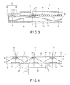
- the reflecting layer 16 is located in the central part of the direct radiation area 15 so as to face the light emitting diode 7. Therefore, the reflecting layers 16 are arranged systematically keeping a distance from each other, so as to correspond to the light emitting diodes 7.
- the reflecting layers 16, which are an example of reflecting means, are formed by applying a white coating to the inner surface 4a of the translucent cover 4, or depositing a material having light diffusion and reflection properties on the inner surface 4a of the translucent cover 4 through vapor deposition.
- the reflecting layer 16 has a lower light transmission rate and a higher degree of light diffusion than the translucent cover 4. Therefore, in-line transmittance of the translucent cover 4 varies in the translucent cover 4, between the part in which the reflecting layer 16 is stacked and the position deviated from the reflecting layer 16.
- the translucent cover 4 includes two kinds of in-line transmittance.
- in-line transmittance of the position corresponding to the optical axis O1 of the light emitting diode 7 is lower than in-line transmittance of the position deviated from the optical axis O1.
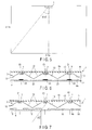
- the reflecting layers 16 are greater in area than the light emitting diodes 7. Accordingly, luminance of the translucent cover 4 is held down when a person looks up the lighting device 1 in the range of angle ⁇ that is defined by the vertical line and the radiation direction of light radiated obliquely downward from the light emitting diodes 7 through the outer circumferential edges of the reflecting layers 16. More specifically, as shown in FIG. 5 , it is known that the main living range of a resident in an eight-tatami room, for example, is within 37.8 degrees with respect to the vertical line that passes the center of the lighting device 1. Therefore, when an eight-mat room is lighted, discomfort glare is reduced by arranging the reflecting layers 16 such that the angle ⁇ 1 in FIG. 4 is 37.8 degrees, as long as the lighting device 1 is looked from below in the above-described living range.
- the reflecting layers 16 are systematically arranged keeping a distance from each other, so as to correspond to the positions of the light emitting diodes 7. Accordingly, light that travels toward the areas between the reflecting layers 16 from the light emitting diodes 7 passes through the translucent cover 4 without being interrupted by the reflecting layers 16.
- the light reflected off the reflecting layers 16 is controlled with respect to luminous intensity distribution by being reflected off the light reflection surfaces 13 of the reflecting mirrors 10. Thereby, the light radiated from the light emitting diodes 7 is effectively taken out without waste outside the lighting device 1, and luminaire efficiency is increased. Furthermore, since light of the light emitting diodes 7 is led to a position in the translucent cover 4 that is deviated from the reflecting layers 16, luminance distribution of the translucent cover 4 is made balanced.
- FIG. 6 discloses a second embodiment of the present invention.
- the second embodiment is different from the first embodiment in configuration of the reflecting layer 21 stacked on the inner surface 4a of the translucent cover 4.
- the configuration of the lighting device 1 is same as that of the first embodiment. Accordingly, the configurations same as those of the first embodiment will be denoted by the same reference numerals, and detailed descriptions of such configurations will be omitted.
- the reflecting layer 21 is stacked on the entire surface of the inner surface 4a of the translucent cover 4.
- the reflecting layer 21 includes a plurality of first areas 22 located right under the light emitting diodes 7 and a plurality of second areas 23 deviated from the light emitting diodes 7.
- the first area 22 has a lower light transmission rate and higher light diffusion properties than the second area 23. Furthermore, the light transmission rate of the first area 22 varies such that the light transmission rate of the central part crossing the optical axis O1 of the light emitting diode 7 is the lowest and the light transmission rate continuously increases as the distance from the central part of the first area 22 increases.
- the in-line transmittance of the part corresponding to the first area 22 of the reflecting layer 21 is lower than the in-line transmittance of the part corresponding to the second area 23, and the in-line transmittance continuously varies depending on the position of the light emitting diode 7.
- the thickness of the white coating forming the reflecting layer 21 may be changed, or the area where the coating is applied may be changed. Furthermore, by changing the size of the material having light diffusion and reflection properties, the in-line transmittance of the translucent cover 4 may be changed.
- the in-line transmittance of the translucent cover 4 varies depending on the position of the light emitting diodes 7. Accordingly, when light from the light emitting diodes 7 is made incident on the translucent cover 4, luminance distribution of the translucent cover 4 is made balanced.
- FIG. 7 discloses a third embodiment of the present invention.
- a plurality of reflecting layers 16 are stacked on the inner surface 4a of the translucent cover 4 at positions deviated from the optical axis O1 of the light emitting diodes 7.
- the in-line transmittance of the position corresponding to the optical axis O1 of the light emitting diode 7 is higher than the in-line transmittance of the position deviated from the optical axis O1.
- light radiated along the optical axis O1 from the light emitting diodes 7 passes through the translucent cover 4 without being interrupted by the reflecting layers 16. Furthermore, a portion of light radiated toward a periphery of the optical axis O1 from the light emitting diode 7 travels toward the reflecting mirror 10, and the remaining light passes through the reflecting layers 16 and the translucent cover 4 and is radiated toward the area below the lighting device 1.
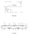
- a worker at his or her desk rarely looks up at the lighting device 1 right above. More specifically, as shown in FIG. 8 , the worker M has more opportunities to look up the lighting device 1 from obliquely below.
- the focus of the experiment for evaluating discomfort glare of the lighting device 1 is the case where the angle ⁇ 3 defined by the line of sight of the worker M and the vertical line exceeds 30 degrees, when the worker M looked up the lighting device 1 from obliquely below.
- FIG. 9 discloses a fourth embodiment of the present invention.
- the reflecting layer 31 is stacked on the entire surface of the inner surface 4a of the translucent cover 4.
- the reflecting layer 31 includes a plurality of first areas 32 located right under the light emitting diodes 7 and a plurality of second areas 33 deviated from the light emitting diodes 7.
- the first areas 32 have a higher light transmission rate, and have lower light diffusion properties than the second areas 33.
- the light transmittance of the first areas 32 varies such that the light transmittance of the central part crossing the optical axis O1 of the light emitting diodes 7 is the highest and the light transmittance seamlessly decreases as the distance from the central part of the first areas 32 including the optical axis O1 increases.
- the in-line transmittance of the parts corresponding to the first areas 32 of the reflecting layer 31 is higher than the in-line transmittance of the parts corresponding to the second areas 33, and the in-line transmittance seamlessly varies depending on the position of the light emitting diodes 7.
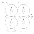
- FIG. 10 to FIG. 12 discloses a fifth embodiment of the present invention.
- the fifth embodiment is different from the first embodiment in shape of a plurality of reflecting mirrors 41 included in a reflector assembly 3. Besides the reflecting mirrors 41, the configuration of the lighting device 1 is same as that of the first embodiment. Accordingly, configurations same as those of the first embodiment will be denoted by the same reference numerals in the fifth embodiment, and detailed descriptions of such configurations will be omitted.
- each of the reflecting mirrors 41 includes a light reflecting surface 42 facing the translucent cover 4.
- the light reflecting surface 42 is a quadric surface of revolution, such as a paraboloid, and is spread toward the translucent cover 4 from the circuit board 6 so as to obtain desired luminous intensity distribution.
- Each of the reflecting mirrors 41 includes a cylindrical reflecting pipe 43.
- the reflecting pipe 43 is an example of a shading angle setting means, and is arranged coaxially with respect to the reflecting mirror 41.
- the reflecting pipe 43 includes a first opening end 44a and a second opening end 44b.
- the first opening end 44a is open in the central part of the light reflecting surface 42 so as to face the inner surface 4a of the translucent cover 4.
- the second opening end 44b is positioned on the opposite side of the first opening end 44a so as to face the mount surface 6a of the circuit board 6.
- the inner surface of the reflecting pipe 43 is a light reflecting surface 45.
- the light reflecting surface 45 connects the second opening end 44b and the first opening end 44a.
- the light emitting diode 7 mounted on the circuit board 6 is located in the second opening end 44b of the reflecting pipe 43. Light emitted by the light emitting diodes 7 is led into the reflecting pipe 43 from the second opening end 44b, and is radiated toward the translucent cover 4 from the first opening end 44a.
- the first opening end 44a of the reflecting pipe 43 is positioned between the light emitting diode 7 and the translucent cover 4. Accordingly, a first shading angle ⁇ 1 is set in the first opening end 44a of the reflecting pipe 43 such that a person cannot directly view the light emitting diode 7 when the person looks up at the lighting device 1 from a position deviated from the optical axis O1.
- the first shading angle ⁇ 1 is set to be equal to or more than 45 degrees.
- a direct radiation area 46 and a peripheral area 47 are defined on the translucent cover 4.
- the direct radiation area 46 is a area on which light radiated from the light emitting diode 7 is directly made incident.
- the direct radiation area 46 is an area defined by a cut-off angle ⁇ obtained by deducting the first shading angle ⁇ 1 from 90 degrees, and is located right under the light emitting diode 7.
- the optical axis O1 of the light emitting diode 7 crosses the direct radiation area 46 in the central part of the direct radiation area 46.
- the peripheral area 47 surrounds the direct radiation area 46.
- the peripheral area 47 faces the outer periphery of the light reflecting surface 42 of the reflecting mirror 41.
- a plurality of semipermeable reflecting films 50 are stacked on the inner surface 4a of the translucent cover 4.
- the semipermeable reflecting film 50 is an example of the first reflecting means, and is located in the direct radiation area 46 so as to face the light emitting diode 7. Accordingly, the semipermeable reflecting films 50 are arranged systematically keeping a distance from each other, so as to correspond to the light emitting diodes 7.
- the semipermeable reflecting film 50 includes a large number of dotted patterns 51 having light reflection properties.
- the pattern 51 are dense in the central part of the direct radiation area 46, through which the optical axis O1 of the light emitting diodes 7 passes, and become coarser as the distance from the optical axis O1 increases. In other words, the interval between the patterns 51 increases as the distance from the central part of the direct radiation area 46 increases toward the outer peripheral part.
- the reflecting mirrors 41 function as the second reflecting means.
- the patterns 51 of the semipermeable reflecting film 50 are denser than the outer peripheral part. Accordingly, the reflection performance of the semipermeable reflecting film 50 is high in the central part of the direct radiation area 46, and the reflection performance of the semipermeable reflecting film 50 decreases as the distance to the outer peripheral part of the direct radiation area 46 decreases. That is, the semipermeable reflecting film 50 has reflection properties such that light reflected toward the light reflecting surface 42 is reduced as the distance from the optical axis O1 of the light emitting diodes 7 increases.
- luminance of the inside of the direct radiation area 46 is moderately reduced by the reflection effect of the semipermeable reflecting film 50.
- luminance of the direct radiation area 46 seamlessly increases as the distance from the central part of the direct radiation area 46 to the outer peripheral part increases.
- the semipermeable reflecting film 50 is provided only in the direct radiation area 46, and the semipermeable reflecting film 50 does not exist in the peripheral area 47 surrounding the direct radiation area 46. Thereby, the in-line transmittance of the direct radiation area 46 is lower than the in-line transmittance of the peripheral area 47.
- each of the reflecting mirrors 41 protrudes toward the translucent cover 4 from the first opening end 44a of the reflecting pipe 43. Accordingly, in the outer circumferential edge of the reflecting mirrors 41, a second shading angle ⁇ 2 is set that hides the first opening end 44a of the reflecting pipe 43 and shields light radiated from the first opening end 44a, when a person looks up at the lighting device 1 from a position deviated from the optical axis O1.
- the second shading angle ⁇ 2 is 30 degrees, for example, and is smaller than the first shading angle ⁇ 1.
- the second shading angle ⁇ 2 is determined by line segment A that connects the first opening end 44a of reflecting pipe 43 and the outer circumferential edge of the reflecting mirror 41. If light emitted from the first opening end 44a of the reflecting pipe 43 is below the line segment A, the light 43 travels toward the translucent cover 4.
- the line segment A extending from a reflecting mirror 41 extends below the outer peripheral part of another adjacent reflecting mirror 41. Thereby, the intersection point B, at which the line segment A crosses the translucent cover 4, is positioned in a boundary between the direct radiation area 46, provided right under said another reflecting mirror 41, and the peripheral area 47.
- light emitted by the light emitting diode 7 is radiated toward the direct radiation area 46 of the translucent cover 4 from the first opening end 44a of the reflection pipe 41.
- a portion of light that has been made incident on the direct radiation area 46 hits the patterns 51 of the semipermeable reflecting film 50 and is reflected toward the light reflecting surface 42, as shown by the arrows in FIG. 10 .
- the light reflected off the semipermeable reflecting film 50 is reflected off the light reflecting surface 42 of the reflecting mirror 41 again, and travels toward the peripheral area 47 of the translucent cover 4.
- the light that travels toward the peripheral area 47 passes through the translucent cover 4, and is radiated toward the area below the lighting device 1.
- the semipermeable reflecting film 50 is stacked on the direct radiation area 46 of the translucent cover 4, on which light radiated from the light emitting diode 7 is directly made incident.
- the existence of the semipermeable reflecting film 50 helps suppress luminance of the direct radiation area 46.
- the second shading angle ⁇ 2 is defined by the outer circumferential edge of the reflecting mirror 41, light radiated from the first opening edge 44a of the reflecting pipe 43 does not easily get into the eyes directly, even when a person looks up the lighting device 1 from a position at a distance. Thereby, discomfort glare is reduced that is caused when a person looks up the lighting device 1.
- light reflected off the semipermeable reflecting film 50 is reflected off the light reflecting surface 42 of the reflecting mirror 41 toward translucent cover 4 again, and is made incident on the peripheral area 47 of the translucent cover 4.
- the light that has been made incident on the peripheral area 47 passes through the translucent cover 4 without causing reflections, and is radiated below the lighting device 1.
- the light reflected off the semipermeable reflecting film 50 is effectively taken out as light for lighting purposes, and luminaire efficiency of the lighting device 1 is increased.
- the intersection point B of the line segment A that defines the second shading angle ⁇ 2 and the translucent cover 4 is positioned in a boundary between the direct radiation area 46 and the peripheral area 47 corresponding to the area right under adjacent reflecting mirror 41. Accordingly, by letting the light radiated from the first opening end 44a of the reflecting pipe 43 penetrate the peripheral area 47 corresponding to the adjacent reflecting mirror 41, light is taken out in the area below the lighting device 1. In other words, when the intersection point B is located in the direct radiation area 46 corresponding to the adjacent reflecting mirror 41, a portion of light emitted by the first opening end 44a of the reflecting pipe 43' is reflected off the semipermeable reflecting film 50 corresponding to the adjacent reflecting mirror 41. Thereby, loss of light occurs, and the ratio of light that passes through the peripheral area 47 decreases.
- the light emitting diodes 7 are not directly recognized visually. In the case of the light emitting diodes 7 using yellow phosphors, the yellow tends to stand out when the lighting device is turned off. By providing the light emitting diodes 7 with a configuration that cannot be directly recognized visually, the color of the light emitting diodes 7 does not become noticeable when the lighting device is turned off.
Landscapes
- Engineering & Computer Science (AREA)
- General Engineering & Computer Science (AREA)
- Physics & Mathematics (AREA)
- Microelectronics & Electronic Packaging (AREA)
- Optics & Photonics (AREA)
- Non-Portable Lighting Devices Or Systems Thereof (AREA)
Applications Claiming Priority (2)
| Application Number | Priority Date | Filing Date | Title |
|---|---|---|---|
| JP2008294727A JP2010123344A (ja) | 2008-11-18 | 2008-11-18 | 照明器具 |
| JP2008306127 | 2008-12-01 |
Publications (1)
| Publication Number | Publication Date |
|---|---|
| EP2187113A1 true EP2187113A1 (fr) | 2010-05-19 |
Family
ID=41682236
Family Applications (1)
| Application Number | Title | Priority Date | Filing Date |
|---|---|---|---|
| EP09014225A Withdrawn EP2187113A1 (fr) | 2008-11-18 | 2009-11-13 | Dispositif d'éclairage incluant un couvercle translucide pour diffuser une lumière à partir d'une source lumineuse |
Country Status (3)
| Country | Link |
|---|---|
| US (1) | US20100124064A1 (fr) |
| EP (1) | EP2187113A1 (fr) |
| CN (1) | CN101737655A (fr) |
Cited By (6)
| Publication number | Priority date | Publication date | Assignee | Title |
|---|---|---|---|---|
| CN102261621A (zh) * | 2010-05-28 | 2011-11-30 | 敦网光电股份有限公司 | 反光结构及光板 |
| WO2013102861A1 (fr) * | 2012-01-04 | 2013-07-11 | Koninklijke Philips Electronics N.V. | Dispositif d'éclairage à del à phosphore distant |
| DE202012103452U1 (de) * | 2012-09-11 | 2013-12-12 | Zumtobel Lighting Gmbh | Rasterleuchte mit LED-Lichtquellen |
| WO2015177771A1 (fr) * | 2014-05-23 | 2015-11-26 | Julie Claire Company Limited | Abat-jour de panneau lumineux |
| EP2917780A4 (fr) * | 2014-02-10 | 2016-04-13 | Lellan Inc | Dispositif de diffusion de lumière |
| EP3453940A1 (fr) * | 2017-09-11 | 2019-03-13 | Krzysztof Skiba | Lampe de plafond |
Families Citing this family (14)
| Publication number | Priority date | Publication date | Assignee | Title |
|---|---|---|---|---|
| TWI422773B (zh) * | 2010-07-15 | 2014-01-11 | Dongguan Masstop Liquid Crystal Display Co Ltd | 光源模組及應用其之檯燈 |
| DE102010041477A1 (de) * | 2010-09-27 | 2012-03-29 | Zumtobel Lighting Gmbh | Anordnung zur Lichtabgabe |
| WO2012158908A2 (fr) | 2011-05-17 | 2012-11-22 | Pixi Lighting Llc | Dispositif d'éclairage à panneau plat et kit de rattrapage |
| CN102997125A (zh) * | 2012-03-07 | 2013-03-27 | 贵溪金泰铜业有限公司 | 一种简洁新颖的发光二极管路灯结构 |
| US9329313B2 (en) | 2012-09-07 | 2016-05-03 | Lockheed Martin Corporation | System and method for photographing cylindrical or spherical objects with reduced glare |
| US9546781B2 (en) | 2013-04-17 | 2017-01-17 | Ever Venture Solutions, Inc. | Field-serviceable flat panel lighting device |
| US9500328B2 (en) | 2013-04-17 | 2016-11-22 | Pixi Lighting, Inc. | Lighting assembly |
| US9476552B2 (en) | 2013-04-17 | 2016-10-25 | Pixi Lighting, Inc. | LED light fixture and assembly method therefor |
| CN104425695B (zh) * | 2013-09-04 | 2017-10-03 | 展晶科技(深圳)有限公司 | 发光二极管 |
| US9557022B2 (en) | 2015-04-30 | 2017-01-31 | Ever Venture Solutions, Inc. | Non-round retrofit recessed LED lighting fixture |
| JP6706982B2 (ja) * | 2016-07-11 | 2020-06-10 | 富士フイルム株式会社 | 面状照明装置 |
| DE102017006424B4 (de) * | 2017-07-07 | 2022-04-21 | Emz-Hanauer Gmbh & Co. Kgaa | Leuchtvorrichtung zum Einbau in eine Wandfläche eines elektrischen Geräts der Haushaltsausstattung |
| JP7316533B2 (ja) * | 2020-09-16 | 2023-07-28 | 株式会社パトライト | レンズ部品及び信号表示灯 |
| CN114216081A (zh) * | 2021-12-22 | 2022-03-22 | 北京数字博文科技发展有限公司 | 防眩光设计的独立柜灯盘 |
Citations (6)
| Publication number | Priority date | Publication date | Assignee | Title |
|---|---|---|---|---|
| FR604343A (fr) * | 1925-10-06 | 1926-05-03 | Main Et Cie G | Appareil d'éclairage électrique pour voies publiques |
| GB513912A (en) * | 1938-03-24 | 1939-10-25 | Edward Rambusch | Improvements in or relating to illuminating devices |
| DE29600945U1 (de) * | 1996-01-15 | 1996-03-21 | Hermann Abke GmbH & Co. Elektro KG, 32584 Löhne | Elektrischer Strahler, insbesondere Halogen-Strahler |
| EP1628070A2 (fr) * | 2004-08-18 | 2006-02-22 | Aldi Einkauf GmbH & Co. oHG | Dispositif d'éclairage |
| EP1645794A2 (fr) * | 2004-10-07 | 2006-04-12 | Choon Nang Electrical Appliance Mfy., Ltd. | Dispositif d'éclairage |
| JP2007214081A (ja) | 2006-02-13 | 2007-08-23 | Seiko Instruments Inc | 照明装置及び表示装置 |
-
2009
- 2009-11-13 EP EP09014225A patent/EP2187113A1/fr not_active Withdrawn
- 2009-11-17 US US12/619,701 patent/US20100124064A1/en not_active Abandoned
- 2009-11-17 CN CN200910221489A patent/CN101737655A/zh active Pending
Patent Citations (6)
| Publication number | Priority date | Publication date | Assignee | Title |
|---|---|---|---|---|
| FR604343A (fr) * | 1925-10-06 | 1926-05-03 | Main Et Cie G | Appareil d'éclairage électrique pour voies publiques |
| GB513912A (en) * | 1938-03-24 | 1939-10-25 | Edward Rambusch | Improvements in or relating to illuminating devices |
| DE29600945U1 (de) * | 1996-01-15 | 1996-03-21 | Hermann Abke GmbH & Co. Elektro KG, 32584 Löhne | Elektrischer Strahler, insbesondere Halogen-Strahler |
| EP1628070A2 (fr) * | 2004-08-18 | 2006-02-22 | Aldi Einkauf GmbH & Co. oHG | Dispositif d'éclairage |
| EP1645794A2 (fr) * | 2004-10-07 | 2006-04-12 | Choon Nang Electrical Appliance Mfy., Ltd. | Dispositif d'éclairage |
| JP2007214081A (ja) | 2006-02-13 | 2007-08-23 | Seiko Instruments Inc | 照明装置及び表示装置 |
Cited By (10)
| Publication number | Priority date | Publication date | Assignee | Title |
|---|---|---|---|---|
| CN102261621A (zh) * | 2010-05-28 | 2011-11-30 | 敦网光电股份有限公司 | 反光结构及光板 |
| CN102261621B (zh) * | 2010-05-28 | 2014-04-30 | 敦网光电股份有限公司 | 反光结构及光板 |
| WO2013102861A1 (fr) * | 2012-01-04 | 2013-07-11 | Koninklijke Philips Electronics N.V. | Dispositif d'éclairage à del à phosphore distant |
| DE202012103452U1 (de) * | 2012-09-11 | 2013-12-12 | Zumtobel Lighting Gmbh | Rasterleuchte mit LED-Lichtquellen |
| EP2917780A4 (fr) * | 2014-02-10 | 2016-04-13 | Lellan Inc | Dispositif de diffusion de lumière |
| CN106030386A (zh) * | 2014-02-10 | 2016-10-12 | 雷斓公司 | 光漫射装置 |
| WO2015177771A1 (fr) * | 2014-05-23 | 2015-11-26 | Julie Claire Company Limited | Abat-jour de panneau lumineux |
| GB2541843A (en) * | 2014-05-23 | 2017-03-01 | Julie Claire Company Ltd | A light panel shade |
| US10288253B2 (en) | 2014-05-23 | 2019-05-14 | Julie Claire Company Limited | Light panel shade |
| EP3453940A1 (fr) * | 2017-09-11 | 2019-03-13 | Krzysztof Skiba | Lampe de plafond |
Also Published As
| Publication number | Publication date |
|---|---|
| US20100124064A1 (en) | 2010-05-20 |
| CN101737655A (zh) | 2010-06-16 |
Similar Documents
| Publication | Publication Date | Title |
|---|---|---|
| US20100124064A1 (en) | Lighting device including translucent cover for diffusing light from light source | |
| EP2458269B1 (fr) | Dispositifs d'éclairage | |
| RU2639980C2 (ru) | Осветительное устройство с круговым распределением света | |
| US9874322B2 (en) | Lensed troffer-style light fixture | |
| JP2013545254A (ja) | トロファ型光学アセンブリ | |
| CN103765092A (zh) | 直视且背视式led照明系统 | |
| TW201224338A (en) | Troffer-style fixture | |
| JP6292509B2 (ja) | 照明装置 | |
| WO2011125010A1 (fr) | Système d'éclairage et luminaire | |
| JP6931809B2 (ja) | 照明器具 | |
| CN104603521B (zh) | 照明装置 | |
| EP2414724A1 (fr) | Réflecteur à chambre de mélange | |
| CA2881470A1 (fr) | Luminaire a rayonnement indirect a surface virtuelle | |
| CN106062465A (zh) | 光源装置以及照明装置 | |
| JP5473966B2 (ja) | 光源ユニット及び照明装置 | |
| US10808911B2 (en) | Luminaire with pyramid-shaped or conical cover | |
| WO2013150380A2 (fr) | Module d'éclairage plat | |
| JP2008078015A (ja) | 照明器具 | |
| JP5472193B2 (ja) | 光源ユニットおよび照明装置 | |
| WO2008102287A1 (fr) | Luminaire à del | |
| KR20220098713A (ko) | 조명 장치 | |
| JP6893326B2 (ja) | 照明器具 | |
| JP2010123344A (ja) | 照明器具 | |
| JP2011129405A (ja) | 照明装置 | |
| JP2010157495A (ja) | 照明器具 |
Legal Events
| Date | Code | Title | Description |
|---|---|---|---|
| PUAI | Public reference made under article 153(3) epc to a published international application that has entered the european phase |
Free format text: ORIGINAL CODE: 0009012 |
|
| 17P | Request for examination filed |
Effective date: 20091113 |
|
| AK | Designated contracting states |
Kind code of ref document: A1 Designated state(s): AT BE BG CH CY CZ DE DK EE ES FI FR GB GR HR HU IE IS IT LI LT LU LV MC MK MT NL NO PL PT RO SE SI SK SM TR |
|
| AX | Request for extension of the european patent |
Extension state: AL BA RS |
|
| 17Q | First examination report despatched |
Effective date: 20101207 |
|
| STAA | Information on the status of an ep patent application or granted ep patent |
Free format text: STATUS: THE APPLICATION IS DEEMED TO BE WITHDRAWN |
|
| 18D | Application deemed to be withdrawn |
Effective date: 20110618 |