EP2187127A1 - Gasturbinenbrennkammer - Google Patents
Gasturbinenbrennkammer Download PDFInfo
- Publication number
- EP2187127A1 EP2187127A1 EP08863965A EP08863965A EP2187127A1 EP 2187127 A1 EP2187127 A1 EP 2187127A1 EP 08863965 A EP08863965 A EP 08863965A EP 08863965 A EP08863965 A EP 08863965A EP 2187127 A1 EP2187127 A1 EP 2187127A1
- Authority
- EP
- European Patent Office
- Prior art keywords
- pilot
- flame
- gas turbine
- turbine combustor
- premixed
- Prior art date
- Legal status (The legal status is an assumption and is not a legal conclusion. Google has not performed a legal analysis and makes no representation as to the accuracy of the status listed.)
- Granted
Links
Images





Classifications
-
- F—MECHANICAL ENGINEERING; LIGHTING; HEATING; WEAPONS; BLASTING
- F23—COMBUSTION APPARATUS; COMBUSTION PROCESSES
- F23D—BURNERS
- F23D14/00—Burners for combustion of a gas, e.g. of a gas stored under pressure as a liquid
- F23D14/46—Details
- F23D14/70—Baffles or like flow-disturbing devices
-
- F—MECHANICAL ENGINEERING; LIGHTING; HEATING; WEAPONS; BLASTING
- F23—COMBUSTION APPARATUS; COMBUSTION PROCESSES
- F23R—GENERATING COMBUSTION PRODUCTS OF HIGH PRESSURE OR HIGH VELOCITY, e.g. GAS-TURBINE COMBUSTION CHAMBERS
- F23R3/00—Continuous combustion chambers using liquid or gaseous fuel
- F23R3/28—Continuous combustion chambers using liquid or gaseous fuel characterised by the fuel supply
- F23R3/286—Continuous combustion chambers using liquid or gaseous fuel characterised by the fuel supply having fuel-air premixing devices
-
- F—MECHANICAL ENGINEERING; LIGHTING; HEATING; WEAPONS; BLASTING
- F23—COMBUSTION APPARATUS; COMBUSTION PROCESSES
- F23R—GENERATING COMBUSTION PRODUCTS OF HIGH PRESSURE OR HIGH VELOCITY, e.g. GAS-TURBINE COMBUSTION CHAMBERS
- F23R3/00—Continuous combustion chambers using liquid or gaseous fuel
- F23R3/28—Continuous combustion chambers using liquid or gaseous fuel characterised by the fuel supply
- F23R3/34—Feeding into different combustion zones
- F23R3/343—Pilot flames, i.e. fuel nozzles or injectors using only a very small proportion of the total fuel to insure continuous combustion
Definitions
- the present invention relates to a gas turbine combustor.
- a pilot burner 3 is arranged at the center position of a combustor main body 2 formed in a cylindrical shape, and a plurality of (for example, eight) main burners 10 are arranged at a uniform pitch in the circumferential direction so as to surround the periphery of the pilot burner 3.
- the pilot burner 3 is provided with a pilot nozzle 4 and a pilot air channel 5 formed around the pilot nozzle 4. Pilot fuel supplied through the pilot nozzle 4 is combusted with pilot air supplied from the pilot air channel 5 and forms a pilot flame extending towards the rear side of a flame stabilizer 9.
- reference numeral 6 is a pilot swirler that is disposed inside the pilot air channel 5 to form a swirling flow
- 7 is a pilot cone formed by expanding the diameter of the downstream end portion of a cylindrical member 8 forming the pilot air channel 5.
- the main burner 10 is provided with a main nozzle 11 and a main air channel 12 that is formed at the periphery of the main nozzle 11.
- Main fuel supplied from the main nozzle 11 is premixed with main air supplied through the main air channel 12 to form premixed gas.
- This premixed gas is combusted downstream of the flame stabilizer 9 by ignition from the pilot flame.
- reference numeral 13 in the figure is a main swirler disposed in the main air channel 12, and it facilitates the premixing with the main fuel by causing the main air to form a swirling flow.
- the above-described gas turbine combustor 1 forms a stable pilot flame (diffusion flame) by the diffusion combustion of the pilot burner 2 and is configured so as to stabilize the premixed flame obtained by combusting the premixed gas by means of ignition whereby this pilot flame bridges to the premixed gas of the main burner 10.
- a gas turbine combustor has been proposed in which, in order to improve the ignition performance of the premixed gas in a premixed combustion region, air injecting means for injecting air towards the downstream side of a tip portion of a pilot cone is provided, and fuel injecting means for injecting fuel in a flame-stabilizing low speed region, or in the vicinity thereof, formed at the downstream side of a tip portion of a pilot cone is provided on the pilot cone (for example, see Patent Citation 2).
- this low-temperature air layer is an air layer having low temperature, it deteriorates the ignition with which the pilot flame forms the premixed flame by combusting the premixed gas; as a result, the combustion of the premixed gas will become unstable. Accordingly, in the gas turbine combustor 1, it is not possible to form a stable premixed flame; therefore, the flame stability of the premixed flame is deteriorated, causing combustion oscillation.
- An object of the present invention which has been made in light of the above circumstances, is to provide, a gas turbine combustor capable of reducing the size of a low-temperature air layer of pilot air formed between a pilot flame and a premixed flame and capable of improving the flame stability of the premixed flame.
- a gas turbine combustor according to the present invention is provided with a pilot burner that is provided at the center portion of a combustor main body formed in a cylindrical shape to form a pilot flame, and a plurality of main burners arranged so as to surround the outer periphery of the pilot burner to form a premixed flame, the gas turbine combustor includes an ignition improving part that reduces the size of a low-temperature air layer of pilot air, formed between the pilot flame and the premixed flame.
- the ignition improving part for reducing the size of the low-temperature air layer of the pilot air formed between the pilot flame and the premixed flame is provided, the low-temperature air layer is made thinner to reduce the distance between the premixed gas and the pilot flame, and thus, the ignition from the pilot flame to the premixed gas is improved.
- the ignition improving part is preferably a channel blocking member provided in the pilot swirler provided in a pilot air channel so as to block one or a plurality of air channels between vanes; accordingly, it is possible to form a region where the low-temperature air layer is thin downstream of the channel blocking member and to reduce the distance between the premixed gas and the pilot flame.
- the ignition improving part is preferably one or a plurality of plate-like projecting members projecting rearward from an outer edge of a pilot cone; accordingly, it is possible to reduce the distance between the premixed gas and the pilot flame by inducing a vortex in the flow of the pilot air with the plate-like projecting member and dragging a part of the premixed gas of the main burner towards the pilot burner.
- the ignition improving part is preferably a wedge-shaped vortex generator that has a sweepback angle and that is provided at one or a plurality of positions on an inner peripheral surface of an outer edge of a pilot cone; accordingly, it is possible to reduce the distance between the premixed gas and the pilot flame by inducing a vortex in the flow of the pilot air with the wedge-shaped vortex generator and dragging a part of the premixed gas of the main burner towards the pilot burner.
- the ignition improving part is preferably one or a plurality of flow-splitting members with a substantially triangular pole-shape provided on an inner peripheral surface of the pilot cone; accordingly, it is possible to reduce the distance between the premixed gas and the pilot flame by forming a region where the low-temperature air layer is thin downstream of the flow-splitting member.
- the ignition improving part is preferably a bypass channel that is formed at an outlet of the pilot cone and by which a part of the pilot air is branched to the main burner side; accordingly, it is possible to reduce the distance between the premixed gas and the pilot flame by forming a region where the low-temperature air layer is thin downstream of the bypass channel.
- bypass channels may be formed entirely or at intervals around the periphery in the circumferential direction of the pilot cone. Note that, since the flow rate of the pilot air being bypassed here is very small compared with the flow rate of the main air to be supplied to the main burner, an adverse effect like dilution of the premixed gas is negligible.
- the ignition improving part is preferably one or a plurality of flow-splitting members with a substantially triangular pole-shape provided at an outlet of a pilot swirler; accordingly, it is possible to reduce the distance between the premixed gas and the pilot flame by forming a region where the low-temperature air layer is thin downstream of the flow-splitting member.
- the ignition improving part is preferably one or a plurality of protruding parts formed on an inner wall surface by subjecting the pilot cone to press working; accordingly, it is possible to reduce the distance between the premixed gas and the pilot flame by forming a region where the low-temperature air layer is thin downstream of the protruding part.
- the ignition improving part is preferably a narrowed portion partially provided at an outlet of a swirler in a pilot air channel; accordingly, it is possible to reduce the distance between the premixed gas and the pilot flame by forming a region where the low-temperature air layer is thin downstream of the narrowed portion.
- an ignition improving part that reduces the size of a low-temperature air layer of pilot air formed between a pilot flame and a premixed flame
- the combustion of the premixed gas is stabilized, forming a stable premixed flame, and therefore, the combustion oscillation of the gas turbine combustor, which is governed by the flame stability of the premixed flame, can be corrected.
- a gas turbine combustor 1A shown in FIG. 1 and FIG. 2 has a configuration in which a pilot burner 3 is provided at the center position of a combustor main body 2 formed in a cylindrical shape, and a plurality of (for example, eight) main burners 10 are provided at a uniform pitch in the circumferential direction so as to surround the periphery of this pilot burner 3.
- the pilot burner 3 is provided with a pilot nozzle 4 that supplies pilot fuel and a pilot air channel 5 that is formed around the pilot nozzle 4 and supplies pilot air thereto.
- the pilot fuel supplied through the pilot nozzle 4 is combusted with the pilot air supplied from the pilot air channel 5 and, as shown in FIG. 2 for example, forms a pilot flame extending rearward of a flame stabilizer 9 from the combustor axial center.
- a pilot swirler 6 that makes the flow of the pilot air become a swirling flow is disposed inside the above-described pilot air channel 5.
- This pilot swirler 6 partitions the interior of the pilot air channel 5 in the circumferential direction and is provided with a plurality of vanes 6a that have a shape that exerts a swirl on the air flow and that are arranged at a uniform pitch. Further, in a cylindrical member 8 forming the pilot air channel 5, a pilot cone 7 formed by expanding the diameter of a downstream end portion thereof is provided.
- the main burner 10 is provided with a main nozzle 11 that supplies main fuel and a main air channel 12 that is formed around the main nozzle 11 and supplies main air.
- the main fuel supplied from the main nozzle 11 is premixed with main air supplied through the main air channel 12 to form premixed gas.
- This premixed gas is combusted by ignition from the pilot flame downstream of the flame stabilizer 9.
- a main swirler 13 that makes the flow of the main air become a swirling flow is disposed in the above-described main air channel 12. Premixing with the main fuel is facilitated with the main air that has become a swirling flow by passing through this main swirler 13.
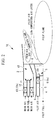
- channel blocking members 20 that reduce the size of the low-temperature air layer of the pilot air formed between the pilot flame and the premixed flame are provided as an ignition improving part.
- channel blocking members 20 are disposed on the pilot swirler 6 provided in the pilot air channel 5 so as to block one or a plurality of positions among the air channels formed between the adjacent vanes 6a.
- four channel blocking members 20 are provided in the air channels between the vanes that are formed by partitioning the air channel 5 into sixteen portions in the circumferential direction by the sixteen vanes 6a constituting the pilot swirler 6 so as to block four air channels between the vanes at a pitch of substantially 90-degree.
- the thus-configured gas turbine combustor 1A forms a region where the low-temperature air layer is thin downstream of the channel blocking members 20; therefore, the distance formed between the premixed gas and the pilot flame can be reduced.
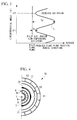
- the horizontal axis is premixed flame plane positions in the gas turbine combustor 1, and a position more to the right-hand-side on the plane of the drawing is towards the outside in the radial direction.
- the vertical axis in FIG. 3 is the circumferential angle of the gas turbine combustor 1, equivalent to the direction in which the above-described four channel blocking members 20 are disposed at a 90-degree pitch.
- a boundary line L which is illustrated by a broken line, between the pilot air region of the low-temperature air layer formed outside the pilot flame plane and the premixed gas region in which premixed gas that has flowed out from the main burner 10 is present varies by following a substantially sinusoidal curve.
- the thickness of the low-temperature air layer varies alternately from the thickest Ta to the thinnest Tb by following the sinusoidal curve.
- the circumferential angles corresponding to Tb where the low-temperature air layer is thinnest are positions ⁇ 1 and ⁇ 2, and the channel blocking members 20 disposed at a 90-degree pitch are present at these positions at the circumferential angles ⁇ 1 and ⁇ 2.
- the reason that the thickness of the low-temperature air layer becomes smaller downstream of the channel blocking members 20 in this way is because the flow rate of the low-temperature pilot air is decreased by blocking the channels of the pilot air flowing in the pilot air channel 5 with the channel blocking plates 20.
- the gas turbine combustor 1A provided with the above-described channel blocker 20 is capable of reducing the distance between the premixed gas and the pilot flame by reducing the thickness of the low-temperature air layer, since the ignition improving part that reduces the size of the low-temperature air layer of the pilot air formed between the pilot flame and the premixed flame is provided.
- the influence of the low-temperature air layer on the pilot flame can be reduced, and so ignition of the premixed gas from the pilot flame can be improved. Since formation of a stable premixed flame becomes possible with the stabilized combustion of the premixed gas, the combustion oscillation of the gas turbine combustor 1A, which is governed by the flame stability of the premixed flame, can be improved.
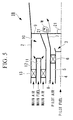
- a gas turbine combustor 1B is provided with one or a plurality of plate-like projecting members 21 projecting rearward from the outer edge of the pilot cone 7 as the ignition improving part.
- four plate-like projecting members 21 arranged at a 90-degree pitch in the circumferential direction are provided so as to project from the rear end of the pilot cone 7 towards the rear flame forming region.
- the cylindrical member 8 of this embodiment employs the pilot cone 7 having plate members 21 at the rear end.
- the flow of the pilot air flowing out through the pilot air channel 5 can induce a vortex at the wake side of the plate-like projecting members 21 (see arrow W in the figure).
- a vortex is induced, a part of the premixed gas of the main burner 10 is dragged towards the pilot burner 3 due to the flow of the vortex.
- the flame forming region provided at the rear side of the flame stabilizer 9 since a part of the premixed gas approaches the pilot flame side, it is possible to reduce the distance between the premixed gas and the pilot flame as a whole.
- the combustion oscillation of the gas turbine combustor 1A which is governed by the flame stability of the premixed flame, can be improved.
- four plate-like projecting members 21 are provided at a 90-degree pitch, at least one or a plurality of plate-like projecting members 21 may be provided. At this time, it is not necessary to arrange the plate-like projecting members 21 at a uniform pitch in the circumferential direction; it is desirable to arrange them at unequal pitches to achieve asymmetry, as a measure against combustion oscillation.
- FIG. 6A a gas turbine combustor 1C in FIG. 6A used here, the outer peripheral side main burner is omitted, and only the pilot burner is illustrated. Note that, in the following description, parts similar to those in the above-described embodiments are assigned the same reference numerals, and a detailed description thereof will thus be omitted.
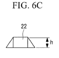
- wedge-shaped vortex generators 22 having a sweepback angle are provided at one or a plurality of positions on the inner peripheral surface of the locations corresponding to the outer edge of the pilot cone 7.
- the cylindrical member 8 in this embodiment employs the pilot cone 7 having the wedge-shaped vortex generators 22 on the inner peripheral surface of the outer edge.
- the combustion oscillation of the gas turbine combustor 1C which is governed by the flame stability of the premixed flame, can be improved.
- four wedge-shaped vortex generators 22 are provided at a 90-degree pitch, at least one or a plurality of wedge-shaped vortex generators 22 may be disposed. At this time, it is not necessary to arrange the wedge-shaped vortex generators 22 at a uniform pitch in the circumferential direction; it is desirable to arrange them at unequal pitches to achieve asymmetry, as a measure against combustion oscillation.
- FIG. 7A and FIG. 7B a fourth embodiment will be described based on FIG. 7A and FIG. 7B .
- the outer peripheral side main burner is omitted, and only the pilot burner is illustrated. Note that, in the following description, parts similar to those in the above-described embodiments are assigned the same reference numerals, and a detailed description thereof will thus be omitted.
- the ignition improving part one or a plurality of flow-splitting members 23 with a substantially triangular pole-shape are provided on the inner peripheral surface of the pilot cone 7. These flow-splitting members 23 are disposed so that the angled tip portion of the triangular pole is located at the upstream side, and the width thereof increases gradually towards the downstream side.
- flow-splitting members 23 are provided at a 90-degree pitch, at least one or a plurality of flow-splitting members 23 may be disposed. At this time, it is not necessary to arrange the flow-splitting members 23 at a uniform pitch in the circumferential direction; it is desirable to arrange them at unequal pitches to achieve asymmetry, as a measure against combustion oscillation.
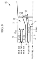
- a gas turbine combustor 1E is provided with, as the ignition improving part, a bypass channel 24 that is formed at the outlet of the pilot cone 7 and with which a part of the pilot air is branched to the main burner 10 side.
- this bypass channel 24 is formed by attaching, for example, a substantially L-shaped cross-section member 25 to the outlet of the pilot cone 7, there is no particular limitation as long as a part of the pilot air is actively guided to the main burner 10 side.
- the bypass channel 24 may be formed around the entire periphery or at intervals in the circumferential direction of the pilot cone 7.
- bypass channels 24 are formed at intervals in the circumferential direction, it is not necessary to arrange the bypass channels 24 at a uniform pitch in the circumferential direction; it is desirable to arrange them at unequal pitches to achieve asymmetry, as a measure against combustion oscillation. Note that, since the flow rate of the pilot air being bypassed here is very small compared with the flow rate of the main air to be supplied to the main burner 10, an adverse effect like dilution of the premixed gas at the main burner 10 side is negligible.
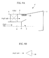
- FIG. 9A a gas turbine combustor 1F in FIG. 9A used here, the outer peripheral side main burner is omitted, and only the pilot burner is illustrated. Note that, in the following description, parts similar to those in the above-described embodiments are assigned the same reference numerals, and a detailed description thereof will thus be omitted.
- the ignition improving part one or a plurality of flow-splitting members 26 with a substantially triangular pole-shape are provided at the outlet of the pilot swirler 6. These flow-splitting members 26 are disposed so that the angled tip portion of the triangular pole is located at the upstream side, and the width thereof increases gradually towards the downstream side.
- flow-splitting members 26 are provided at a 90-degree pitch, at least one or a plurality of flow-splitting members 26 may be disposed. At this time, it is not necessary to arrange the flow-splitting members 26 at a uniform pitch in the circumferential direction; it is desirable to arrange them at unequal pitches to achieve asymmetry, as a measure against combustion oscillation.
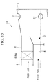
- a seventh embodiment will be described based on FIG. 10 .
- the outer peripheral side main burner is omitted, and only the pilot burner is illustrated. Note that, in the following description, parts similar to those in the above-described embodiments are assigned the same reference numerals, and a detailed description thereof will thus be omitted.
- the ignition improving part one or a plurality of protruding parts 27 that are formed on the inner wall surface by subjecting the pilot cone 7 to the press working are provided. These protruding parts 27 are a low-cost structure since they are formed by subjecting the pilot cone 7 to partial press working from the outside to cause the inner peripheral surface to protrude inwardly.
- protruding parts 27 are provided at a 90-degree pitch, at least one or a plurality of protruding parts 27 may be disposed. At this time, it is not necessary to arrange the protruding parts 27 at a uniform pitch in the circumferential direction; it is desirable to arrange them at unequal pitches to achieve asymmetry, as a measure against combustion oscillation.
- FIG. 11A and FIG. 11B an eighth embodiment will be described based on FIG. 11A and FIG. 11B .
- the outer peripheral side main burner is omitted, and only the pilot burner is illustrated. Note that, in the following description, parts similar to those in the above-described embodiments are assigned the same reference numerals, and a detailed description thereof will thus be omitted.
- the ignition improving part partially narrowed portions 28 are provided at a swirler outlet of the pilot air channel 5. These narrowed portions 28 are formed by partially extending a rear-end cone part 5a of the pilot nozzle 5 whose diameter is expanded towards the wake side.
- the narrowed portions 28 in which the normal channel dimension S has been narrowed to Sa are formed at the swirler outlet of the pilot air channel 5.
- a region where the low-temperature air layer is thin can be formed downstream of the narrowed portions 28, and therefore, it is possible to reduce the distance between the premixed gas and the pilot flame.
- the tongue-shaped parts 5b are provided at a uniform pitch around the entire periphery in the circumferential direction, these tongue-shaped parts 5b may be either disposed at a part of the circumferential direction or disposed at unequal pitches in the circumferential direction.
- a stable pilot flame (diffusion flame) is formed by means of the diffusion combustion of the pilot burner 2; and with the improved ignition by which this pilot flame bridges to the premixed gas of the main burner 10, the premixed flame obtained by the combustion of the premixed gas will also be stabilized.
- the combustion of the premixed gas is stabilized, forming a stable premixed flame, and so the combustion oscillation of the gas turbine combustor, which is governed by the flame stability of the premixed flame, can be improved.
- the present invention is not limited to the above-described embodiments; suitable modifications, such as, for example, employing suitably combined configurations of each embodiment, are possible without departing from the spirit of the invention.
Landscapes
- Engineering & Computer Science (AREA)
- Chemical & Material Sciences (AREA)
- Combustion & Propulsion (AREA)
- Mechanical Engineering (AREA)
- General Engineering & Computer Science (AREA)
- Gas Burners (AREA)
Applications Claiming Priority (2)
| Application Number | Priority Date | Filing Date | Title |
|---|---|---|---|
| JP2007329955A JP5173393B2 (ja) | 2007-12-21 | 2007-12-21 | ガスタービン燃焼器 |
| PCT/JP2008/073177 WO2009081856A1 (ja) | 2007-12-21 | 2008-12-19 | ガスタービン燃焼器 |
Publications (3)
| Publication Number | Publication Date |
|---|---|
| EP2187127A1 true EP2187127A1 (de) | 2010-05-19 |
| EP2187127A4 EP2187127A4 (de) | 2014-08-13 |
| EP2187127B1 EP2187127B1 (de) | 2016-03-09 |
Family
ID=40801157
Family Applications (1)
| Application Number | Title | Priority Date | Filing Date |
|---|---|---|---|
| EP08863965.3A Active EP2187127B1 (de) | 2007-12-21 | 2008-12-19 | Gasturbinenbrennkammer |
Country Status (6)
| Country | Link |
|---|---|
| US (3) | US8794004B2 (de) |
| EP (1) | EP2187127B1 (de) |
| JP (1) | JP5173393B2 (de) |
| KR (1) | KR20100018604A (de) |
| CN (1) | CN101743442B (de) |
| WO (1) | WO2009081856A1 (de) |
Cited By (3)
| Publication number | Priority date | Publication date | Assignee | Title |
|---|---|---|---|---|
| EP2416070A1 (de) * | 2010-08-02 | 2012-02-08 | Siemens Aktiengesellschaft | Gasturbinenbrennkammer |
| ITMI20111943A1 (it) * | 2011-10-26 | 2013-04-27 | Ansaldo Energia Spa | Metodo per modificare un gruppo bruciatore di una turbina a gas |
| CN114165813A (zh) * | 2021-12-03 | 2022-03-11 | 北京航空航天大学 | 一种双油路供油的气动辅助一体化支板稳定器 |
Families Citing this family (13)
| Publication number | Priority date | Publication date | Assignee | Title |
|---|---|---|---|---|
| US9557050B2 (en) * | 2010-07-30 | 2017-01-31 | General Electric Company | Fuel nozzle and assembly and gas turbine comprising the same |
| US20120144832A1 (en) * | 2010-12-10 | 2012-06-14 | General Electric Company | Passive air-fuel mixing prechamber |
| JP6021108B2 (ja) * | 2012-02-14 | 2016-11-02 | 三菱日立パワーシステムズ株式会社 | ガスタービン燃焼器 |
| WO2015178149A1 (ja) * | 2014-05-23 | 2015-11-26 | 三菱日立パワーシステムズ株式会社 | ガスタービン燃焼器及びガスタービン |
| US10317083B2 (en) * | 2014-10-03 | 2019-06-11 | Pratt & Whitney Canada Corp. | Fuel nozzle |
| JP6417620B2 (ja) * | 2014-10-24 | 2018-11-07 | 三菱日立パワーシステムズ株式会社 | 燃焼器、ガスタービン |
| KR102236267B1 (ko) * | 2016-04-08 | 2021-04-05 | 한화에어로스페이스 주식회사 | 산업용 연소기 |
| US10337738B2 (en) | 2016-06-22 | 2019-07-02 | General Electric Company | Combustor assembly for a turbine engine |
| US11022313B2 (en) | 2016-06-22 | 2021-06-01 | General Electric Company | Combustor assembly for a turbine engine |
| US10197279B2 (en) | 2016-06-22 | 2019-02-05 | General Electric Company | Combustor assembly for a turbine engine |
| CN106705045B (zh) * | 2017-01-22 | 2019-08-09 | 中国科学院工程热物理研究所 | 一种内外流道当量比可调的喷嘴、喷嘴阵列和燃烧器 |
| JP6934359B2 (ja) * | 2017-08-21 | 2021-09-15 | 三菱パワー株式会社 | 燃焼器及びその燃焼器を備えるガスタービン |
| US11181269B2 (en) | 2018-11-15 | 2021-11-23 | General Electric Company | Involute trapped vortex combustor assembly |
Family Cites Families (15)
| Publication number | Priority date | Publication date | Assignee | Title |
|---|---|---|---|---|
| US3919840A (en) | 1973-04-18 | 1975-11-18 | United Technologies Corp | Combustion chamber for dissimilar fluids in swirling flow relationship |
| US3974646A (en) | 1974-06-11 | 1976-08-17 | United Technologies Corporation | Turbofan engine with augmented combustion chamber using vorbix principle |
| US4044553A (en) * | 1976-08-16 | 1977-08-30 | General Motors Corporation | Variable geometry swirler |
| GB2085146B (en) * | 1980-10-01 | 1985-06-12 | Gen Electric | Flow modifying device |
| JPH05203146A (ja) * | 1992-01-29 | 1993-08-10 | Hitachi Ltd | ガスタービン燃焼器及びガスタービン発電装置 |
| US5487274A (en) | 1993-05-03 | 1996-01-30 | General Electric Company | Screech suppressor for advanced low emissions gas turbine combustor |
| DE19510744A1 (de) * | 1995-03-24 | 1996-09-26 | Abb Management Ag | Brennkammer mit Zweistufenverbrennung |
| JPH0942672A (ja) * | 1995-08-04 | 1997-02-14 | Hitachi Ltd | ガスタービン燃焼器 |
| US6122916A (en) * | 1998-01-02 | 2000-09-26 | Siemens Westinghouse Power Corporation | Pilot cones for dry low-NOx combustors |
| JP2001141241A (ja) * | 1999-11-12 | 2001-05-25 | Tokyo Electric Power Co Inc:The | ガスタービン燃焼器 |
| JP2001254946A (ja) * | 2000-03-14 | 2001-09-21 | Mitsubishi Heavy Ind Ltd | ガスタービン燃焼器 |
| JP2003139326A (ja) | 2001-11-02 | 2003-05-14 | Ishikawajima Harima Heavy Ind Co Ltd | ガスタービンの燃焼器 |
| JP2005114193A (ja) | 2003-10-03 | 2005-04-28 | Mitsubishi Heavy Ind Ltd | ガスタービン燃焼器 |
| US7779636B2 (en) * | 2005-05-04 | 2010-08-24 | Delavan Inc | Lean direct injection atomizer for gas turbine engines |
| CN100570216C (zh) * | 2005-06-24 | 2009-12-16 | 株式会社日立制作所 | 喷烧器、燃气轮机燃烧器、喷烧器的冷却方法及喷烧器的改造方法 |
-
2007
- 2007-12-21 JP JP2007329955A patent/JP5173393B2/ja active Active
-
2008
- 2008-12-19 CN CN2008800245088A patent/CN101743442B/zh active Active
- 2008-12-19 EP EP08863965.3A patent/EP2187127B1/de active Active
- 2008-12-19 KR KR1020107000037A patent/KR20100018604A/ko not_active Ceased
- 2008-12-19 WO PCT/JP2008/073177 patent/WO2009081856A1/ja not_active Ceased
- 2008-12-19 US US12/666,673 patent/US8794004B2/en active Active
-
2014
- 2014-06-27 US US14/317,357 patent/US9791149B2/en active Active
- 2014-06-27 US US14/317,363 patent/US9612013B2/en active Active
Cited By (8)
| Publication number | Priority date | Publication date | Assignee | Title |
|---|---|---|---|---|
| EP2416070A1 (de) * | 2010-08-02 | 2012-02-08 | Siemens Aktiengesellschaft | Gasturbinenbrennkammer |
| WO2012016748A3 (de) * | 2010-08-02 | 2013-03-21 | Siemens Aktiengesellschaft | Gasturbinenbrennkammer |
| RU2566866C2 (ru) * | 2010-08-02 | 2015-10-27 | Сименс Акциенгезелльшафт | Камера сгорания газовой турбины |
| US9194587B2 (en) | 2010-08-02 | 2015-11-24 | Siemens Aktiengesellschaft | Gas turbine combustion chamber |
| ITMI20111943A1 (it) * | 2011-10-26 | 2013-04-27 | Ansaldo Energia Spa | Metodo per modificare un gruppo bruciatore di una turbina a gas |
| WO2013061303A1 (en) * | 2011-10-26 | 2013-05-02 | Ansaldo Energia S.P.A. | Method for modifying a gas turbine burner assembly |
| CN114165813A (zh) * | 2021-12-03 | 2022-03-11 | 北京航空航天大学 | 一种双油路供油的气动辅助一体化支板稳定器 |
| CN114165813B (zh) * | 2021-12-03 | 2022-08-30 | 北京航空航天大学 | 一种双油路供油的气动辅助一体化支板稳定器 |
Also Published As
| Publication number | Publication date |
|---|---|
| KR20100018604A (ko) | 2010-02-17 |
| US8794004B2 (en) | 2014-08-05 |
| CN101743442A (zh) | 2010-06-16 |
| JP5173393B2 (ja) | 2013-04-03 |
| JP2009150615A (ja) | 2009-07-09 |
| US20140305095A1 (en) | 2014-10-16 |
| CN101743442B (zh) | 2011-12-07 |
| US20100319351A1 (en) | 2010-12-23 |
| US9612013B2 (en) | 2017-04-04 |
| WO2009081856A1 (ja) | 2009-07-02 |
| EP2187127B1 (de) | 2016-03-09 |
| EP2187127A4 (de) | 2014-08-13 |
| US20140305094A1 (en) | 2014-10-16 |
| US9791149B2 (en) | 2017-10-17 |
Similar Documents
| Publication | Publication Date | Title |
|---|---|---|
| US9791149B2 (en) | Gas turbine combustor | |
| US10544939B2 (en) | Burner for a can combustor | |
| US8065880B2 (en) | Premixed combustion burner for gas turbine | |
| JP4087375B2 (ja) | ガスタービンエンジン燃焼器 | |
| US9518740B2 (en) | Axial swirler for a gas turbine burner | |
| EP2496884B1 (de) | Injektionssystem für einen nachbrenner | |
| US9976744B2 (en) | Reheat burner arrangement having an increasing flow path cross-section | |
| US8677756B2 (en) | Reheat burner injection system | |
| US11365885B2 (en) | Gas turbine combustor with fuel injector including a downstream guide member | |
| JP2006300448A (ja) | ガスタービンの燃焼器 | |
| US10920986B2 (en) | Gas turbine combustor base plate configuration | |
| US9194587B2 (en) | Gas turbine combustion chamber | |
| EP3438539B1 (de) | Gasturbinenbrennkammer |
Legal Events
| Date | Code | Title | Description |
|---|---|---|---|
| PUAI | Public reference made under article 153(3) epc to a published international application that has entered the european phase |
Free format text: ORIGINAL CODE: 0009012 |
|
| 17P | Request for examination filed |
Effective date: 20100112 |
|
| AK | Designated contracting states |
Kind code of ref document: A1 Designated state(s): AT BE BG CH CY CZ DE DK EE ES FI FR GB GR HR HU IE IS IT LI LT LU LV MC MT NL NO PL PT RO SE SI SK TR |
|
| AX | Request for extension of the european patent |
Extension state: AL BA MK RS |
|
| DAX | Request for extension of the european patent (deleted) | ||
| A4 | Supplementary search report drawn up and despatched |
Effective date: 20140716 |
|
| RIC1 | Information provided on ipc code assigned before grant |
Ipc: F23R 3/14 20060101AFI20140710BHEP Ipc: F23R 3/30 20060101ALI20140710BHEP Ipc: F23R 3/34 20060101ALI20140710BHEP |
|
| RAP1 | Party data changed (applicant data changed or rights of an application transferred) |
Owner name: MITSUBISHI HITACHI POWER SYSTEMS, LTD. |
|
| RAP1 | Party data changed (applicant data changed or rights of an application transferred) |
Owner name: MITSUBISHI HITACHI POWER SYSTEMS, LTD. |
|
| GRAP | Despatch of communication of intention to grant a patent |
Free format text: ORIGINAL CODE: EPIDOSNIGR1 |
|
| INTG | Intention to grant announced |
Effective date: 20150710 |
|
| GRAS | Grant fee paid |
Free format text: ORIGINAL CODE: EPIDOSNIGR3 |
|
| GRAA | (expected) grant |
Free format text: ORIGINAL CODE: 0009210 |
|
| AK | Designated contracting states |
Kind code of ref document: B1 Designated state(s): AT BE BG CH CY CZ DE DK EE ES FI FR GB GR HR HU IE IS IT LI LT LU LV MC MT NL NO PL PT RO SE SI SK TR |
|
| REG | Reference to a national code |
Ref country code: GB Ref legal event code: FG4D |
|
| REG | Reference to a national code |
Ref country code: AT Ref legal event code: REF Ref document number: 779808 Country of ref document: AT Kind code of ref document: T Effective date: 20160315 Ref country code: CH Ref legal event code: EP |
|
| REG | Reference to a national code |
Ref country code: IE Ref legal event code: FG4D |
|
| REG | Reference to a national code |
Ref country code: DE Ref legal event code: R096 Ref document number: 602008042745 Country of ref document: DE |
|
| REG | Reference to a national code |
Ref country code: LT Ref legal event code: MG4D |
|
| REG | Reference to a national code |
Ref country code: NL Ref legal event code: MP Effective date: 20160309 |
|
| PG25 | Lapsed in a contracting state [announced via postgrant information from national office to epo] |
Ref country code: FI Free format text: LAPSE BECAUSE OF FAILURE TO SUBMIT A TRANSLATION OF THE DESCRIPTION OR TO PAY THE FEE WITHIN THE PRESCRIBED TIME-LIMIT Effective date: 20160309 Ref country code: GR Free format text: LAPSE BECAUSE OF FAILURE TO SUBMIT A TRANSLATION OF THE DESCRIPTION OR TO PAY THE FEE WITHIN THE PRESCRIBED TIME-LIMIT Effective date: 20160610 Ref country code: ES Free format text: LAPSE BECAUSE OF FAILURE TO SUBMIT A TRANSLATION OF THE DESCRIPTION OR TO PAY THE FEE WITHIN THE PRESCRIBED TIME-LIMIT Effective date: 20160309 Ref country code: NO Free format text: LAPSE BECAUSE OF FAILURE TO SUBMIT A TRANSLATION OF THE DESCRIPTION OR TO PAY THE FEE WITHIN THE PRESCRIBED TIME-LIMIT Effective date: 20160609 Ref country code: HR Free format text: LAPSE BECAUSE OF FAILURE TO SUBMIT A TRANSLATION OF THE DESCRIPTION OR TO PAY THE FEE WITHIN THE PRESCRIBED TIME-LIMIT Effective date: 20160309 |
|
| REG | Reference to a national code |
Ref country code: AT Ref legal event code: MK05 Ref document number: 779808 Country of ref document: AT Kind code of ref document: T Effective date: 20160309 |
|
| PG25 | Lapsed in a contracting state [announced via postgrant information from national office to epo] |
Ref country code: PL Free format text: LAPSE BECAUSE OF FAILURE TO SUBMIT A TRANSLATION OF THE DESCRIPTION OR TO PAY THE FEE WITHIN THE PRESCRIBED TIME-LIMIT Effective date: 20160309 Ref country code: LV Free format text: LAPSE BECAUSE OF FAILURE TO SUBMIT A TRANSLATION OF THE DESCRIPTION OR TO PAY THE FEE WITHIN THE PRESCRIBED TIME-LIMIT Effective date: 20160309 Ref country code: SE Free format text: LAPSE BECAUSE OF FAILURE TO SUBMIT A TRANSLATION OF THE DESCRIPTION OR TO PAY THE FEE WITHIN THE PRESCRIBED TIME-LIMIT Effective date: 20160309 Ref country code: NL Free format text: LAPSE BECAUSE OF FAILURE TO SUBMIT A TRANSLATION OF THE DESCRIPTION OR TO PAY THE FEE WITHIN THE PRESCRIBED TIME-LIMIT Effective date: 20160309 Ref country code: LT Free format text: LAPSE BECAUSE OF FAILURE TO SUBMIT A TRANSLATION OF THE DESCRIPTION OR TO PAY THE FEE WITHIN THE PRESCRIBED TIME-LIMIT Effective date: 20160309 |
|
| PG25 | Lapsed in a contracting state [announced via postgrant information from national office to epo] |
Ref country code: IS Free format text: LAPSE BECAUSE OF FAILURE TO SUBMIT A TRANSLATION OF THE DESCRIPTION OR TO PAY THE FEE WITHIN THE PRESCRIBED TIME-LIMIT Effective date: 20160709 Ref country code: EE Free format text: LAPSE BECAUSE OF FAILURE TO SUBMIT A TRANSLATION OF THE DESCRIPTION OR TO PAY THE FEE WITHIN THE PRESCRIBED TIME-LIMIT Effective date: 20160309 |
|
| PG25 | Lapsed in a contracting state [announced via postgrant information from national office to epo] |
Ref country code: CZ Free format text: LAPSE BECAUSE OF FAILURE TO SUBMIT A TRANSLATION OF THE DESCRIPTION OR TO PAY THE FEE WITHIN THE PRESCRIBED TIME-LIMIT Effective date: 20160309 Ref country code: PT Free format text: LAPSE BECAUSE OF FAILURE TO SUBMIT A TRANSLATION OF THE DESCRIPTION OR TO PAY THE FEE WITHIN THE PRESCRIBED TIME-LIMIT Effective date: 20160711 Ref country code: AT Free format text: LAPSE BECAUSE OF FAILURE TO SUBMIT A TRANSLATION OF THE DESCRIPTION OR TO PAY THE FEE WITHIN THE PRESCRIBED TIME-LIMIT Effective date: 20160309 Ref country code: SK Free format text: LAPSE BECAUSE OF FAILURE TO SUBMIT A TRANSLATION OF THE DESCRIPTION OR TO PAY THE FEE WITHIN THE PRESCRIBED TIME-LIMIT Effective date: 20160309 Ref country code: RO Free format text: LAPSE BECAUSE OF FAILURE TO SUBMIT A TRANSLATION OF THE DESCRIPTION OR TO PAY THE FEE WITHIN THE PRESCRIBED TIME-LIMIT Effective date: 20160309 |
|
| REG | Reference to a national code |
Ref country code: DE Ref legal event code: R097 Ref document number: 602008042745 Country of ref document: DE |
|
| PG25 | Lapsed in a contracting state [announced via postgrant information from national office to epo] |
Ref country code: BE Free format text: LAPSE BECAUSE OF FAILURE TO SUBMIT A TRANSLATION OF THE DESCRIPTION OR TO PAY THE FEE WITHIN THE PRESCRIBED TIME-LIMIT Effective date: 20160309 Ref country code: IT Free format text: LAPSE BECAUSE OF FAILURE TO SUBMIT A TRANSLATION OF THE DESCRIPTION OR TO PAY THE FEE WITHIN THE PRESCRIBED TIME-LIMIT Effective date: 20160309 |
|
| PLBE | No opposition filed within time limit |
Free format text: ORIGINAL CODE: 0009261 |
|
| STAA | Information on the status of an ep patent application or granted ep patent |
Free format text: STATUS: NO OPPOSITION FILED WITHIN TIME LIMIT |
|
| PG25 | Lapsed in a contracting state [announced via postgrant information from national office to epo] |
Ref country code: DK Free format text: LAPSE BECAUSE OF FAILURE TO SUBMIT A TRANSLATION OF THE DESCRIPTION OR TO PAY THE FEE WITHIN THE PRESCRIBED TIME-LIMIT Effective date: 20160309 |
|
| 26N | No opposition filed |
Effective date: 20161212 |
|
| PG25 | Lapsed in a contracting state [announced via postgrant information from national office to epo] |
Ref country code: BG Free format text: LAPSE BECAUSE OF FAILURE TO SUBMIT A TRANSLATION OF THE DESCRIPTION OR TO PAY THE FEE WITHIN THE PRESCRIBED TIME-LIMIT Effective date: 20160609 |
|
| PG25 | Lapsed in a contracting state [announced via postgrant information from national office to epo] |
Ref country code: SI Free format text: LAPSE BECAUSE OF FAILURE TO SUBMIT A TRANSLATION OF THE DESCRIPTION OR TO PAY THE FEE WITHIN THE PRESCRIBED TIME-LIMIT Effective date: 20160309 |
|
| REG | Reference to a national code |
Ref country code: CH Ref legal event code: PL |
|
| GBPC | Gb: european patent ceased through non-payment of renewal fee |
Effective date: 20161219 |
|
| PG25 | Lapsed in a contracting state [announced via postgrant information from national office to epo] |
Ref country code: MC Free format text: LAPSE BECAUSE OF FAILURE TO SUBMIT A TRANSLATION OF THE DESCRIPTION OR TO PAY THE FEE WITHIN THE PRESCRIBED TIME-LIMIT Effective date: 20160309 |
|
| REG | Reference to a national code |
Ref country code: FR Ref legal event code: ST Effective date: 20170831 |
|
| REG | Reference to a national code |
Ref country code: IE Ref legal event code: MM4A |
|
| PG25 | Lapsed in a contracting state [announced via postgrant information from national office to epo] |
Ref country code: FR Free format text: LAPSE BECAUSE OF NON-PAYMENT OF DUE FEES Effective date: 20170102 Ref country code: CH Free format text: LAPSE BECAUSE OF NON-PAYMENT OF DUE FEES Effective date: 20161231 Ref country code: LI Free format text: LAPSE BECAUSE OF NON-PAYMENT OF DUE FEES Effective date: 20161231 Ref country code: LU Free format text: LAPSE BECAUSE OF NON-PAYMENT OF DUE FEES Effective date: 20161219 |
|
| PG25 | Lapsed in a contracting state [announced via postgrant information from national office to epo] |
Ref country code: IE Free format text: LAPSE BECAUSE OF NON-PAYMENT OF DUE FEES Effective date: 20161219 Ref country code: GB Free format text: LAPSE BECAUSE OF NON-PAYMENT OF DUE FEES Effective date: 20161219 |
|
| PG25 | Lapsed in a contracting state [announced via postgrant information from national office to epo] |
Ref country code: CY Free format text: LAPSE BECAUSE OF FAILURE TO SUBMIT A TRANSLATION OF THE DESCRIPTION OR TO PAY THE FEE WITHIN THE PRESCRIBED TIME-LIMIT Effective date: 20160309 Ref country code: HU Free format text: LAPSE BECAUSE OF FAILURE TO SUBMIT A TRANSLATION OF THE DESCRIPTION OR TO PAY THE FEE WITHIN THE PRESCRIBED TIME-LIMIT; INVALID AB INITIO Effective date: 20081219 |
|
| PG25 | Lapsed in a contracting state [announced via postgrant information from national office to epo] |
Ref country code: TR Free format text: LAPSE BECAUSE OF FAILURE TO SUBMIT A TRANSLATION OF THE DESCRIPTION OR TO PAY THE FEE WITHIN THE PRESCRIBED TIME-LIMIT Effective date: 20160309 |
|
| PG25 | Lapsed in a contracting state [announced via postgrant information from national office to epo] |
Ref country code: MT Free format text: LAPSE BECAUSE OF NON-PAYMENT OF DUE FEES Effective date: 20161219 |
|
| REG | Reference to a national code |
Ref country code: DE Ref legal event code: R082 Ref document number: 602008042745 Country of ref document: DE Representative=s name: HENKEL & PARTNER MBB PATENTANWALTSKANZLEI, REC, DE Ref country code: DE Ref legal event code: R081 Ref document number: 602008042745 Country of ref document: DE Owner name: MITSUBISHI POWER, LTD., JP Free format text: FORMER OWNER: MITSUBISHI HITACHI POWER SYSTEMS, LTD., YOKOHAMA-SHI, KANAGAWA, JP |
|
| PGFP | Annual fee paid to national office [announced via postgrant information from national office to epo] |
Ref country code: DE Payment date: 20251028 Year of fee payment: 18 |