EP2187151B1 - Eisspendetechnologie - Google Patents
Eisspendetechnologie Download PDFInfo
- Publication number
- EP2187151B1 EP2187151B1 EP09008457.5A EP09008457A EP2187151B1 EP 2187151 B1 EP2187151 B1 EP 2187151B1 EP 09008457 A EP09008457 A EP 09008457A EP 2187151 B1 EP2187151 B1 EP 2187151B1
- Authority
- EP
- European Patent Office
- Prior art keywords
- ice
- duct
- dispensing
- control part
- cap
- Prior art date
- Legal status (The legal status is an assumption and is not a legal conclusion. Google has not performed a legal analysis and makes no representation as to the accuracy of the status listed.)
- Not-in-force
Links
Images


Classifications
-
- F—MECHANICAL ENGINEERING; LIGHTING; HEATING; WEAPONS; BLASTING
- F25—REFRIGERATION OR COOLING; COMBINED HEATING AND REFRIGERATION SYSTEMS; HEAT PUMP SYSTEMS; MANUFACTURE OR STORAGE OF ICE; LIQUEFACTION SOLIDIFICATION OF GASES
- F25B—REFRIGERATION MACHINES, PLANTS OR SYSTEMS; COMBINED HEATING AND REFRIGERATION SYSTEMS; HEAT PUMP SYSTEMS
- F25B49/00—Arrangement or mounting of control or safety devices
-
- F—MECHANICAL ENGINEERING; LIGHTING; HEATING; WEAPONS; BLASTING
- F25—REFRIGERATION OR COOLING; COMBINED HEATING AND REFRIGERATION SYSTEMS; HEAT PUMP SYSTEMS; MANUFACTURE OR STORAGE OF ICE; LIQUEFACTION SOLIDIFICATION OF GASES
- F25C—PRODUCING, WORKING OR HANDLING ICE
- F25C5/00—Working or handling ice
- F25C5/20—Distributing ice
-
- F—MECHANICAL ENGINEERING; LIGHTING; HEATING; WEAPONS; BLASTING
- F25—REFRIGERATION OR COOLING; COMBINED HEATING AND REFRIGERATION SYSTEMS; HEAT PUMP SYSTEMS; MANUFACTURE OR STORAGE OF ICE; LIQUEFACTION SOLIDIFICATION OF GASES
- F25C—PRODUCING, WORKING OR HANDLING ICE
- F25C1/00—Producing ice
- F25C1/22—Construction of moulds; Filling devices for moulds
- F25C1/24—Construction of moulds; Filling devices for moulds for refrigerators, e.g. freezing trays
-
- F—MECHANICAL ENGINEERING; LIGHTING; HEATING; WEAPONS; BLASTING
- F25—REFRIGERATION OR COOLING; COMBINED HEATING AND REFRIGERATION SYSTEMS; HEAT PUMP SYSTEMS; MANUFACTURE OR STORAGE OF ICE; LIQUEFACTION SOLIDIFICATION OF GASES
- F25C—PRODUCING, WORKING OR HANDLING ICE
- F25C5/00—Working or handling ice
- F25C5/02—Apparatus for disintegrating, removing or harvesting ice
-
- F—MECHANICAL ENGINEERING; LIGHTING; HEATING; WEAPONS; BLASTING
- F25—REFRIGERATION OR COOLING; COMBINED HEATING AND REFRIGERATION SYSTEMS; HEAT PUMP SYSTEMS; MANUFACTURE OR STORAGE OF ICE; LIQUEFACTION SOLIDIFICATION OF GASES
- F25D—REFRIGERATORS; COLD ROOMS; ICE-BOXES; COOLING OR FREEZING APPARATUS NOT OTHERWISE PROVIDED FOR
- F25D29/00—Arrangement or mounting of control or safety devices
-
- F—MECHANICAL ENGINEERING; LIGHTING; HEATING; WEAPONS; BLASTING
- F25—REFRIGERATION OR COOLING; COMBINED HEATING AND REFRIGERATION SYSTEMS; HEAT PUMP SYSTEMS; MANUFACTURE OR STORAGE OF ICE; LIQUEFACTION SOLIDIFICATION OF GASES
- F25C—PRODUCING, WORKING OR HANDLING ICE
- F25C2600/00—Control issues
- F25C2600/02—Timing
-
- F—MECHANICAL ENGINEERING; LIGHTING; HEATING; WEAPONS; BLASTING
- F25—REFRIGERATION OR COOLING; COMBINED HEATING AND REFRIGERATION SYSTEMS; HEAT PUMP SYSTEMS; MANUFACTURE OR STORAGE OF ICE; LIQUEFACTION SOLIDIFICATION OF GASES
- F25C—PRODUCING, WORKING OR HANDLING ICE
- F25C2600/00—Control issues
- F25C2600/04—Control means
-
- F—MECHANICAL ENGINEERING; LIGHTING; HEATING; WEAPONS; BLASTING
- F25—REFRIGERATION OR COOLING; COMBINED HEATING AND REFRIGERATION SYSTEMS; HEAT PUMP SYSTEMS; MANUFACTURE OR STORAGE OF ICE; LIQUEFACTION SOLIDIFICATION OF GASES
- F25C—PRODUCING, WORKING OR HANDLING ICE
- F25C5/00—Working or handling ice
- F25C5/20—Distributing ice
- F25C5/22—Distributing ice particularly adapted for household refrigerators
Definitions
- the present disclosure relates to ice dispensing technology.
- a refrigerator is a home appliance that can store foods in a freezing state or a refrigeration state.
- a refrigerator may include a dispenser that can dispense ice and/or water to an outside of the refrigerator.
- the refrigerator provided with the dispenser includes devices for making and dispensing the ice.
- WO 2008/030023 describes a control apparatus for taking out ice of a refrigerator and a method thereof.
- a control apparatus comprises an input unit for inputting the amount of ice to be taken out, a taking-out unit for taking out the ice corresponding to the amount inputted to the input unit, a control unit for controlling the input unit and the taking-out unit, an ice-making unit for generating ice by controlling of the control unit, a state information storage unit for storing at least one information between the inputted amount for taking out and the amount of ice generated by the ice-making unit, and a display unit for displaying information stored in the state information storage unit.
- a control method for taking out ice of a refrigerator in which ice is generated and stored by control of a control unit. Thereafter, the amount of ice to be taken out is inputted and the ice corresponding to the inputted amount is taken out. After sensing the amount of ice taken out, the inputted amount of ice for taking out is compared with the sensed amount of ice, and it is determined whether or not the ice is to be taken based on the comparison result.
- WO 2008/030023 discloses an ice-making device according to the preamble of claim 1.
- an ice-making device including a duct through which ice is dispensed; a duct-covering part for opening and closing the duct; an ice conveying part for conveying the ice dispensed through the duct; and a control part for controlling the duct-covering part and the ice conveying part: characterized in that the control part is configured to linearly increase a driving speed of the ice conveying part for an initial driving time when a signal to start dispensing of ice is received, and the control part is configured to drive the ice conveying part at a target speed when the initial driving time elapses.
- a method of controlling an ice-making device comprising: controlling, using a control part, a duct-covering part to open a duct in response to a signal to start dispensing of ice; in response to the signal to start dispensing of ice, increasing, using the control part and during a first period of time after receiving the signal to start dispensing of ice, a driving speed of an ice conveying part, which is configured to promote movement of ice through the duct; and driving, using the control part and during a second period of time that is different than and immediately subsequent to the first period of time, the ice conveying part at a target speed.
- FIG. 1 illustrates an example of a refrigerator with an ice-making device
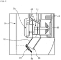
- FIG. 2 illustrates a cross-section of an example of a part of an ice-making device
- FIG. 3 illustrates an example configuration of an ice dispensing control system
- FIG. 4 illustrates operations of a duct cap and an ice conveying motor when dispensing of ice starts.
- a refrigerator compartment 3 and a freezer compartment are disposed in a main body 1.
- the refrigerator compartment 3 and the freezer compartment, where foods are stored, are arranged vertically in the main body 1, with the refrigerator compartment 3 being positioned above the freezer compartment.
- the refrigerator compartment 3 is opened and closed by refrigerator compartment doors 5 and 6 and the freezer compartment is opened and closed by a freezer compartment door 7.
- An ice-making chamber 9 is provided to an inner surface of the refrigerator compartment door 5 (hereinafter, referred to as a "door").
- the ice-making chamber 9 is separated from the refrigerator compartment 3.
- An ice-making device including an ice maker (not shown) for making ice and an ice bin 50 for storing the ice made in the ice maker is disposed inside the ice-making chamber 9.
- a dispenser (not shown) is provided on a front surface of the door 5.
- the dispenser is used to dispense water and/or ice without opening the door 5.
- an ice duct 10 is disposed inside the door 5.
- the ice duct 10 is used to dispense the ice stored in the ice bin 50 to the outside of the refrigerator, that is, to the outside of the refrigerator through the dispenser which transports ice through the door 5 when the door 5 is in a closed position.
- a first end of the ice duct 10 communicates with the ice bin and a second end of the ice duct 10 communicates with the dispenser.
- a duct cap 20 opens and closes an end of the ice duct 10 adjacent to the dispenser (e.g., the second end of the ice duct 10 that communicates with the dispenser) .
- One end of the duct cap 20 rotates about the other end to open and close the ice duct 10.
- a hall sensor 30 and a magnet 40 are disposed on the ice duct 10 and the duct cap 20, respectively.
- the hall sensor 30 and the magnet 40 may be disposed at positions at which the ice duct 10 faces the duct cap 20.
- the hall sensor 30 and the magnet 40 sense a position of the duct cap 20 with respect to the ice duct 10.
- the hall sensor 30 disposed on the ice duct 10 senses strength (e.g., presence or absence) of a magnetic field of the magnet 40 disposed on the duct cap 20 to sense the position of the duct cap 20 with respect to the ice duct 10.
- the hall sensor 30 senses a relatively strong (e.g., a present) magnetic field and detects that the duct cap 20 is in a position to close the ice duct 10.
- the hall sensor 30 senses a relatively weak (e.g., an absent) magnetic field and detects that the duct cap 20 is in a position to open the ice duct 10.
- An ice dispensing opening 51 is defined in a bottom surface of the ice bin 50 disposed inside the ice-making chamber 9.
- the ice dispensing opening 51 serves as an outlet port through which the ice stored in the ice bin 50 is dispensed to the outside of the ice bin 50.
- the ice dispensing opening 51 communicates with one end portion of the ice duct 10 (e.g., the first end of the ice duct 10 that communicates with the ice bin 50).
- An ice conveying gear 60 is disposed inside the ice bin 50 adjacent to the ice dispensing opening 51.
- the ice conveying gear 60 conveys the ice stored in the ice bin 50 to dispense the ice through the ice dispensing opening 51.
- An ice conveying motor 70 is disposed on a side of the ice-making chamber 9.
- the ice conveying motor 70 provides a driving force for operating the ice conveying gear 60.
- the ice conveying motor 70 may be coupled to the ice conveying gear 60 in a state where the ice bin 50 is disposed inside the ice-making chamber 9. Alternatively, the ice conveying motor 70 may be disposed on a side of the ice bin 50.
- an input part 100 receives an operation signal for dispensing the ice through the dispenser.
- a dispensing lever may be used as the input part 100.
- the dispensing lever may be disposed on a side of the dispenser and pressed by a container for receiving the ice by a user.
- an operation signal for dispensing the ice through the dispenser is received.
- an operation signal for finishing the dispensing of the ice through the dispenser is received.
- Other types of dispensing buttons or input controls may be used as the input part 100.
- a cap-driving part 200 provides a driving force for rotating the duct cap 20.
- the cap-driving part 200 may include a solenoid valve or a motor. That is, the cap-driving part 200 rotates in a predetermined direction or a reverse direction to allow the duct cap 20 to open or close one end of the ice duct 10.
- a control part 300 controls the dispensing of the ice through the dispenser. For instance, the control part 300 controls the cap-driving part 200 according to the operation signals inputted to the input part 100 to rotate the duct cap 20, and thereby, to close or open the ice duct 10.
- the control part 300 controls operation of the ice conveying motor 70 according to the operation signal inputted into the input part 100. For example, the control part 300 controls the ice conveying motor 70 to rotate the ice conveying gear 60 to convey ice when a dispensing signal is received and stops the ice conveying motor 70 to stop the operation of the ice conveying gear 60 when a dispensing signal is not received or an end dispensing signal is received.
- the control part 300 controls the cap-driving part 200 to allow the duct cap 20 to open the ice duct 10 when the input part 100 receives the operation signal for dispensing the ice through the dispenser.
- the control part 300 controls the cap-driving part 200 to allow the duct cap 20 to close the ice duct 10 when the input 100 receives the operation signal for finishing the dispensing of the ice through the dispenser.
- the control part 300 controls the cap-driving part 200 to allow the duct cap 20 to close the ice duct 10 after the input part 100 receives the operation signal for finishing the dispensing of the ice through the dispenser, and a set period of time has elapsed after the input part 100 receives the operation signal for finishing the dispensing of the ice through the dispenser. This may be done to enable closing of the ice duct 10 only after the ice positioned in the ice duct 10 is completely dispensed even if the input part 100 receives the operation signal for finishing the dispensing of the ice through the dispenser when ice remains in the ice duct 10.
- the control part 300 controls the ice conveying motor 70 to operate at a previously set target speed.
- the control part 300 increases a driving speed of the ice conveying motor 70, which operates the ice conveying gear 60, for the previously set time after which the ice conveying motor 70 operates at the previously set target speed
- the control part 300 controls the ice conveying motor 70 to operate at the target speed by increasing the driving speed of the ice conveying motor 70 the driving speed reaches the target speed.
- the target speed may be defined as a speed previously set according to the operation signals inputted into the input part 100.
- the previously set time may be set to a time reaching the target speed by increasing the driving speed of the ice conveying motor 70.
- control part 300 controls the driving speed of the ice conveying motor 70 to linearly increase for the previously set time.
- the control part 300 controls the ice conveying motor 70 to stop the operation of the ice conveying motor 70 when the input part 100 receives the operation signal for finishing the dispensing of the ice through the dispenser.
- FIG. 5 illustrates an example of a method of controlling an ice-making device.
- an input part 100 receives an operation signal for starting dispensing of ice through a dispenser (S11).
- the input part 100 may receive the operation signal for starting the dispensing of the ice through the dispenser by receiving a user's press of an operation button (not shown) or receiving a user's press of a lever (not shown) with a container for receiving ice.
- a control part 300 controls an operation of a cap-driving part 200 to allow a duct cap 20 to open an ice duct 10 (S13).
- the control part 300 controls an ice conveying motor 70 to increase a driving speed of the ice conveying motor 70 (S15).
- the ice conveying motor 70 When the ice conveying motor 70 is driven (S15), the ice is dispensed (S17) .
- the ice stored in an ice bin 50 is dispensed by an ice conveying gear 60 operated by driving the ice conveying motor 70 through the ice duct 10 opened by the duct cap 20.
- the driving speed of the ice conveying motor 70 increases (S15), it may reduce the possibility of the ice conveying motor 70 being overloaded as a result of ice being positioned between the ice conveying gear 60 and the ice duct 10 or the ice bin 50 during an initial time period at which the ice is conveyed by the ice conveying gear 60.
- the control part 300 determines whether a driving time of the ice conveying motor 70 has passed a previously set time (S19). When the driving time of the ice conveying motor 70 passes the previously set time (S19), the control part 300 controls the ice conveying motor 70 to drive the ice conveying motor 70 at a previously set target speed (S21). Thus, a further amount of ice can be dispensed through the ice duct 10.
- the control part 300 determines whether the dispensing of the ice through the ice duct 10 is finished (S23). For example, whether the dispensing of the ice through the ice duct 10 is finished (S23) may be determined according to whether the input part 100 receives an operation signal for finishing the dispensing of the ice, according to whether the input part 100 further receives the operation signal for dispensing the ice (e.g., whether a user continues to supply a constant pressing force to a dispensing control button or lever), or according to whether an ice dispensing time set according to the operation signal for dispensing the ice and inputted to the input part 100 is finished.
- S23 may be determined according to whether the input part 100 receives an operation signal for finishing the dispensing of the ice, according to whether the input part 100 further receives the operation signal for dispensing the ice (e.g., whether a user continues to supply a constant pressing force to a dispensing control button or lever), or according to whether an ice dispensing time set
- the control part 300 controls the ice conveying motor 70 to stop an operation of the ice conveying motor 70 (S25).
- the control part 300 determines whether a previously set time elapses after the operation of the ice conveying motor 70 stops (S27).
- the previously set time may be the same previously set time used in driving the ice conveying motor 70 (S19) or may be a different previously set time.
- the control part 300 controls the cap-driving part 200 to allow the duct cap 20 to close the ice duct 10 (S29).
- the ice duct 10 maintains in open state for the previously set time even if the ice conveying motor stops, the ice duct 10 is closed after the ice stored in the ice duct 10 is completely dispensed to the outside.
- FIG. 6 illustrates an example of a method of controlling an ice-making device.
- an input part receives an operation signal to start dispensing of ice (S31).
- a control part 300 controls an operation of a cap-driving part 200 to allow a duct cap 20 to open an ice duct 10 (S33) .
- the control part 300 controls the ice conveying motor 70 to increase a driving speed of the ice conveying motor 70 (S35) .
- the ice conveyed by an ice conveying gear 60 is dispensed through the ice duct 10 (S37).
- the control part 300 determines whether the driving speed of the ice conveying motor 70 reaches a previously set target speed (S39). When the driving speed of the ice conveying motor 70 reaches the previously set target speed (S39), the control part 300 controls the ice conveying motor 70 to drive the ice conveying motor 70 at the target speed (S41).
- the control part 300 determines whether the dispensing of the ice through the ice duct 10 is finished (S43). When the dispensing of the ice is finished, the control part 300 controls the ice conveying motor 70 to stop an operation of the ice conveying motor 70 (S45). When the dispensing of the ice is finished (S43), and the operation of the ice conveying motor 70. stops (S45), the control part 300 determines whether a previously set time elapses after the operation of the ice conveying motor 70 stops (S47). The control part 300 controls the cap-driving part 200 to allow the duct cap 20 to close the ice duct 10 (S49).
- the ice-making device has been described as being installed in the ice-making chamber disposed on a back surface of the refrigerator compartment door, the present disclosure is not limited thereto.
- the ice-making device may be installed in an ice-making chamber located inside of the refrigerator compartment door (e.g., within a storage space defined by the refrigerator compartment and separate from the door).
- the ice-making device may be installed on a back surface of a freezer compartment door or located inside of the freezer compartment door (e.g., within a storage space defined by the freezer compartment and separate from the door).
- the duct cap 20 is not limited to a rotating operation to open or close the ice duct.
- the duct cap may be translated (e.g., slid) to open or close the ice duct.
- the ice duct is a member for dispensing the ice
- the duct cap is a member for opening or closing the member for dispensing the ice.
- the present disclosure is not limited thereto.
- the ice made in the ice maker is stored in the ice bin in the above implementations, the present disclosure is not limited thereto.
- the ice made in the ice maker may be stored in a member having a different name, e.g., an ice bank.
- the driving speed of the ice conveying motor increases for a previously set time until the driving speed of the ice conveying motor reaches a previously set target speed after the ice duct is opened.
- gradually increasing the driving speed of the ice conveying motor to the target speed may reduce the likelihood of the ice conveying motor being overloaded as a result of ice being positioned between the ice conveying gear and the ice duct or the ice bin during the initial dispensing of the ice. Therefore, the potential for damage of the ice conveying motor may be reduced.
- the dispensing speed of the ice since the driving speed of the ice conveying motor increases for the previously set time until the driving speed of the ice conveying motor reaches the previously set target speed, the dispensing speed of the ice substantially and gradually increases. Therefore, noise and breakage and/or blockage of the ice generated during the initial dispensing of the ice may be reduced.
Landscapes
- Engineering & Computer Science (AREA)
- Physics & Mathematics (AREA)
- Mechanical Engineering (AREA)
- Thermal Sciences (AREA)
- General Engineering & Computer Science (AREA)
- Chemical & Material Sciences (AREA)
- Combustion & Propulsion (AREA)
- Production, Working, Storing, Or Distribution Of Ice (AREA)
- Devices That Are Associated With Refrigeration Equipment (AREA)
- Beverage Vending Machines With Cups, And Gas Or Electricity Vending Machines (AREA)
Claims (13)
- Eisbereitungsvorrichtung, die Folgendes umfasst:einen Schacht (10), durch den Eis ausgegeben wird;ein Schachtabdeckteil (20) zum Öffnen und Schließen des Schachts (10);ein Eisförderteil (60) zum Fördern von Eis, das durch den Schacht (10) ausgegeben wird; undein Steuerungsteil (300) zum Steuern des Schachtabdeckteils (20) und des Eisförderteils (60),dadurch gekennzeichnet, dass das Steuerungsteil (300) konfiguriert ist, eine Antriebsgeschwindigkeit des Eisförderteils (60) für eine anfängliche Antriebszeit linear zu erhöhen, wenn ein Signal zum Starten der Ausgabe von Eis empfangen wird, und dass das Steuerungsteil (300) konfiguriert ist, das Eisförderteil (60) mit einer Sollgeschwindigkeit anzutreiben, wenn die anfängliche Antriebszeit verstrichen ist.
- Eisbereitungsvorrichtung nach Anspruch 1, wobei das Schachtabdeckteil (20) konfiguriert ist, den Schacht (10) zu öffnen, um einen Durchgang von Eis durch den Schacht (10) zu ermöglichen, wenn ein Eingabeteil (100) ein Betriebssignal empfängt, die Ausgabe von Eis zu starten.
- Eisbereitungsvorrichtung nach Anspruch 1, wobei das Schachtabdeckteil (20) konfiguriert ist, dann, wenn die Ausgabe von Eis beendet ist, den Schacht (10) zu schließen, nachdem der Betrieb des Eisförderteils (60) stoppt und eine eingestellte Zeitspanne verstrichen ist.
- Eisbereitungsvorrichtung nach einem der Ansprüche 1 bis 3, wobei die Ausgabe von Eis startet, indem ein Eingabeteil (100) eingeschaltet wird und beendet wird, indem das Eingabeteil (100) ausgeschaltet wird.
- Eisbereitungsvorrichtung nach Anspruch 4, wobei das Schachtabdeckteil (20) Folgendes umfasst:einen Motor (70) zum Fördern von Eis, der eine Antriebskraft zum Fördern wenigstens von Eis bereitstellt; undein Kappenantriebsteil (200), das eine Antriebskraft zum Öffnen oder Schließen wenigstens des Schachts (10) bereitstellt.
- Eisbereitungsvorrichtung nach Anspruch 1,
wobei ein erstes Ende des Schachts (10) mit einem Eiskasten (50) zum Lagern von Eis kommuniziert und ein zweites Ende des Eisschachts (10) mit einem Spender zum Ausgeben von Wasser und/oder Eis kommuniziert,
wobei das Schachtabdeckteil (20) als eine Schachtkappe vorgesehen ist, die ein Ende des Eisschachts (10) bei dem Spender öffnet und schließt, wobei sich ein Ende der Schachtkappe um das andere Ende dreht, um den Schacht (10) zu öffnen und zu schließen,
wobei die Eisbereitungsvorrichtung ferner Folgendes umfasst:einen Hallsensor (40), der an dem Schacht (10) angeordnet ist; undeinen Magneten (40), der an der Schachtkappe (20) angeordnet ist,wobei in dem Zustand, in dem die Schachtkappe (20) den Schacht (10) schließt, der Hallsensor (30) und der Magnet (40) an Positionen angeordnet sind, an denen der Schacht (10) zu der Schachtkappe (20) zeigt,
wobei der Hallsensor (30) und der Magnet (40) eine Position der Schachtkappe (20) in Bezug auf den Schacht (10) messen,
wobei der Hallsensor (30), der an dem Schacht (10) angeordnet ist, eine Stärke eines Magnetfelds des Magneten (40), der an dem Schachtabdeckteil (20) angeordnet ist, misst, um die Position der Schachtkappe (20) in Bezug auf den Schacht (10) zu messen, wobei dann, wenn die Schachtkappe (20) den Schacht (10) öffnet, der Hallsensor (30) ein relativ schwaches Magnetfeld misst und detektiert, dass sich die Schachtkappe (20) in einer Position zum Öffnen des Schachts (10) befindet,
und wobei dann, wenn die Schachtkappe (20) den Schacht (10) schließt, der Hallsensor (30) ein relativ starkes Magnetfeld misst und detektiert, dass sich die Schachtkappe (20) in einer Position zum Schließen des Eisschachts (10) befindet. - Verfahren zum Steuern einer Eisbereitungsvorrichtung, wobei das Verfahren die folgenden Schritte umfasst:unter Verwendung eines Steuerungsteils (300) Steuern eines Schachtabdeckteils (20), einen Schacht (10) in Reaktion auf ein Signal zum Starten der Ausgabe von Eis zu öffnen;in Reaktion auf das Signal zum Starten der Ausgabe von Eis unter Verwendung des Steuerungsteils (300) und während einer ersten Zeitspanne nach dem Empfangen des Signals zum Starten der Ausgabe von Eis, Erhöhen einer Antriebsgeschwindigkeit eines Eisförderteils (60), das konfiguriert ist, eine Bewegung von Eis durch den Schacht (10) zu unterstützen; undunter Verwendung des Steuerungsteils (300) und während einer zweiten Zeitspanne, die sich von der ersten Zeitspanne unterscheidet und unmittelbar auf diese folgt, Antreiben des Eisförderteils (60) mit einer Sollgeschwindigkeit.
- Verfahren nach Anspruch 7, wobei die erste Zeitspanne eine zuvor eingestellte anfängliche Antriebszeit ist und wobei das Erhöhen der Antriebsgeschwindigkeit für die zuvor eingestellte anfängliche Antriebszeit fortgesetzt durchgeführt wird.
- Verfahren nach Anspruch 7 oder 8, wobei das Erhöhen der Antriebsgeschwindigkeit fortgesetzt durchgeführt wird, bis die Antriebsgeschwindigkeit des Eisförderteils (60) die Sollgeschwindigkeit erreicht.
- Verfahren nach einem der Ansprüche 7 bis 9, das ferner die folgenden Schritte umfasst:unter Verwendung des Steuerungsteils (300) Stoppen des Eisförderteils (60), wenn die Ausgabe von Eis beendet ist; undunter Verwendung des Steuerungsteils (300) Steuern des Schachtabdeckteils (20), den Schacht (10) zu schließen, wenn das Eisförderteil (60) gestoppt ist.
- Verfahren nach Anspruch 10, wobei:das Steuern unter Verwendung des Steuerungsteils (300) des Schachtabdeckteils (20), den Schacht (10) in Reaktion auf das Signal zum Starten einer Ausgabe von Eis zu öffnen, das Empfangen unter Verwendung eines Eingabeteils (100) eines Betriebssignals zum Starten der Ausgabe von Eis umfasst, und das Stoppen unter Verwendung des Steuerungsteils (300) des Eisförderteils (60), wenn die Ausgabe von Eis beendet ist, das Feststellen, dass die Ausgabe von Eis beendet ist, auf der Basis davon, dass unter Verwendung des Eingabeteils (100) ein Betriebssignal zum Beenden der Ausgabe von Eis empfangen wird, das Feststellen, dass die Eingabe zum Starten der Ausgabe von Eis, die unter Verwendung des Eingabeteils (100) empfangen wurde, beendet ist, und/oder das Feststellen, dass eine Eisausgabezeit, die auf der Basis der Eingabe eingestellt wurde, die Ausgabe von Eis zu starten, die unter Verwendung des Eingabeteils (100) empfangen wurde, beendet ist, umfasst.
- Verfahren nach Anspruch 10, das ferner unter Verwendung des Steuerungsteils (300) das Steuern des Schachtabdeckteils (20) umfasst, den Schacht (10) zu schließen, wenn nach dem Stoppen des Eisförderteils (60) eine eingestellte Zeitspanne verstrichen ist.
- Verfahren nach Anspruch 12, wobei das Steuern unter Verwendung des Steuerungsteils (300) des Schachabdeckteils (20), den Schacht (10) zu schließen, wenn eine eingestellte Zeitspanne nach dem Stoppen des Eisförderteils (60) verstrichen ist, das Messen unter Verwendung des Steuerungsteils (300) einer Zeit, seit der der Betrieb des Eisförderteils (60) gestoppt ist, das Vergleichen unter Verwendung des Steuerungsteils (300) der gemessenen Zeit mit der eingestellten Zeitspanne und das Auslösen unter Verwendung des Steuerungsteils (300) des Schließens des Schachts (10), wenn der Vergleich erbringt, dass die eingestellte Zeitspanne verstrichen ist, umfasst.
Applications Claiming Priority (1)
| Application Number | Priority Date | Filing Date | Title |
|---|---|---|---|
| KR1020080113686A KR101517619B1 (ko) | 2008-11-14 | 2008-11-14 | 제빙장치 및 그 제어방법 |
Publications (3)
| Publication Number | Publication Date |
|---|---|
| EP2187151A2 EP2187151A2 (de) | 2010-05-19 |
| EP2187151A3 EP2187151A3 (de) | 2011-06-01 |
| EP2187151B1 true EP2187151B1 (de) | 2019-02-27 |
Family
ID=41674189
Family Applications (1)
| Application Number | Title | Priority Date | Filing Date |
|---|---|---|---|
| EP09008457.5A Not-in-force EP2187151B1 (de) | 2008-11-14 | 2009-06-29 | Eisspendetechnologie |
Country Status (4)
| Country | Link |
|---|---|
| US (1) | US8240156B2 (de) |
| EP (1) | EP2187151B1 (de) |
| KR (1) | KR101517619B1 (de) |
| CN (1) | CN101738046B (de) |
Families Citing this family (10)
| Publication number | Priority date | Publication date | Assignee | Title |
|---|---|---|---|---|
| US10275778B1 (en) | 2013-03-15 | 2019-04-30 | Palantir Technologies Inc. | Systems and user interfaces for dynamic and interactive investigation based on automatic malfeasance clustering of related data in various data structures |
| US8788405B1 (en) | 2013-03-15 | 2014-07-22 | Palantir Technologies, Inc. | Generating data clusters with customizable analysis strategies |
| US10579647B1 (en) | 2013-12-16 | 2020-03-03 | Palantir Technologies Inc. | Methods and systems for analyzing entity performance |
| US9256664B2 (en) | 2014-07-03 | 2016-02-09 | Palantir Technologies Inc. | System and method for news events detection and visualization |
| US9367872B1 (en) | 2014-12-22 | 2016-06-14 | Palantir Technologies Inc. | Systems and user interfaces for dynamic and interactive investigation of bad actor behavior based on automatic clustering of related data in various data structures |
| US10489391B1 (en) | 2015-08-17 | 2019-11-26 | Palantir Technologies Inc. | Systems and methods for grouping and enriching data items accessed from one or more databases for presentation in a user interface |
| US10974893B1 (en) * | 2018-12-03 | 2021-04-13 | CWMF Corporation | Batcher gate for asphalt silo handling |
| US11009278B2 (en) * | 2018-12-10 | 2021-05-18 | Midea Group Co., Ltd. | Refrigerator with variable ice dispenser |
| US10845117B2 (en) | 2018-12-10 | 2020-11-24 | Midea Group Co., Ltd. | Refrigerator with variable fluid dispenser |
| CN118662023B (zh) * | 2023-03-15 | 2025-04-15 | 九阳股份有限公司 | 一种食品加工机低噪音的粉碎方法及其制浆方法 |
Family Cites Families (11)
| Publication number | Priority date | Publication date | Assignee | Title |
|---|---|---|---|---|
| US4787539A (en) * | 1986-06-19 | 1988-11-29 | Hoshizaki Electric Co., Ltd. | Ice dispenser |
| KR100271357B1 (ko) | 1997-12-31 | 2000-11-01 | 윤종용 | 냉장고 및 그 제어방법 |
| JP3393589B2 (ja) * | 1998-02-17 | 2003-04-07 | ホシザキ電機株式会社 | アイスディスペンサ |
| EP1482261B1 (de) * | 2003-05-28 | 2014-01-01 | LG Electronics, Inc. | Eisversorgungsanordnung |
| US7062925B2 (en) | 2003-06-24 | 2006-06-20 | Hoshizaki Denki Kabushiki Kaisha | Method of operating auger icemaking machine |
| JP4435509B2 (ja) | 2003-06-24 | 2010-03-17 | ホシザキ電機株式会社 | オーガ式製氷機の運転方法 |
| KR100565622B1 (ko) * | 2003-09-19 | 2006-03-30 | 엘지전자 주식회사 | 냉장고 |
| KR100565497B1 (ko) * | 2003-10-07 | 2006-03-30 | 엘지전자 주식회사 | 만빙 감지 장치 및 그 감지 방법 |
| KR20050105315A (ko) | 2004-04-28 | 2005-11-04 | 엘지전자 주식회사 | 냉장고 얼음이송장치의 제어회로 |
| US8646285B2 (en) | 2006-09-04 | 2014-02-11 | Lg Electronics Inc. | Control apparatus for taking out ice of refrigerator and method thereof |
| KR20080022466A (ko) * | 2006-09-06 | 2008-03-11 | 삼성전자주식회사 | 냉장고 |
-
2008
- 2008-11-14 KR KR1020080113686A patent/KR101517619B1/ko active Active
-
2009
- 2009-06-22 US US12/488,628 patent/US8240156B2/en active Active
- 2009-06-29 EP EP09008457.5A patent/EP2187151B1/de not_active Not-in-force
- 2009-10-16 CN CN2009102051702A patent/CN101738046B/zh active Active
Non-Patent Citations (1)
| Title |
|---|
| None * |
Also Published As
| Publication number | Publication date |
|---|---|
| CN101738046B (zh) | 2012-07-18 |
| KR101517619B1 (ko) | 2015-05-04 |
| EP2187151A3 (de) | 2011-06-01 |
| US20100122546A1 (en) | 2010-05-20 |
| US8240156B2 (en) | 2012-08-14 |
| KR20100054679A (ko) | 2010-05-25 |
| CN101738046A (zh) | 2010-06-16 |
| EP2187151A2 (de) | 2010-05-19 |
Similar Documents
| Publication | Publication Date | Title |
|---|---|---|
| EP2187151B1 (de) | Eisspendetechnologie | |
| US8025186B2 (en) | Refrigerator and method of controlling the same | |
| EP2187153B1 (de) | Eisausgabetechnologie | |
| US8196426B2 (en) | Refrigerator dispenser control technology | |
| EP2459948B1 (de) | Kühlschrank und regelungsverfahren dafür | |
| US20120111031A1 (en) | Refrigerator and method for controlling the same | |
| JPH11108550A (ja) | 冷蔵庫用ディスペンサーアセンブリ及びその制御方法 | |
| US8336331B2 (en) | Refrigerator | |
| KR100903923B1 (ko) | 냉장고 | |
| EP2357436B1 (de) | Kühlschrank und betriebsverfahren | |
| EP2024697B1 (de) | Kühlschrank | |
| CN100449232C (zh) | 冰箱 | |
| EP1429092B1 (de) | Kühlschrank mit einer Eisabgabevorrichtung | |
| EP2187152B1 (de) | Eisspendetechnologie | |
| KR20110040221A (ko) | 디스펜서를 통한 급수량 제어방법 및 그를 이용한 냉장고 | |
| CN100356122C (zh) | 控制冰箱的方法 | |
| US11530861B2 (en) | Refrigerator and control method thereof | |
| KR101322317B1 (ko) | 얼음 취출 장치 |
Legal Events
| Date | Code | Title | Description |
|---|---|---|---|
| PUAI | Public reference made under article 153(3) epc to a published international application that has entered the european phase |
Free format text: ORIGINAL CODE: 0009012 |
|
| AK | Designated contracting states |
Kind code of ref document: A2 Designated state(s): AT BE BG CH CY CZ DE DK EE ES FI FR GB GR HR HU IE IS IT LI LT LU LV MC MK MT NL NO PL PT RO SE SI SK TR |
|
| AX | Request for extension of the european patent |
Extension state: AL BA RS |
|
| PUAL | Search report despatched |
Free format text: ORIGINAL CODE: 0009013 |
|
| AK | Designated contracting states |
Kind code of ref document: A3 Designated state(s): AT BE BG CH CY CZ DE DK EE ES FI FR GB GR HR HU IE IS IT LI LT LU LV MC MK MT NL NO PL PT RO SE SI SK TR |
|
| AX | Request for extension of the european patent |
Extension state: AL BA RS |
|
| 17P | Request for examination filed |
Effective date: 20110826 |
|
| 17Q | First examination report despatched |
Effective date: 20150508 |
|
| GRAP | Despatch of communication of intention to grant a patent |
Free format text: ORIGINAL CODE: EPIDOSNIGR1 |
|
| STAA | Information on the status of an ep patent application or granted ep patent |
Free format text: STATUS: GRANT OF PATENT IS INTENDED |
|
| INTG | Intention to grant announced |
Effective date: 20180920 |
|
| RAP1 | Party data changed (applicant data changed or rights of an application transferred) |
Owner name: LG ELECTRONICS INC. |
|
| GRAS | Grant fee paid |
Free format text: ORIGINAL CODE: EPIDOSNIGR3 |
|
| GRAA | (expected) grant |
Free format text: ORIGINAL CODE: 0009210 |
|
| STAA | Information on the status of an ep patent application or granted ep patent |
Free format text: STATUS: THE PATENT HAS BEEN GRANTED |
|
| AK | Designated contracting states |
Kind code of ref document: B1 Designated state(s): AT BE BG CH CY CZ DE DK EE ES FI FR GB GR HR HU IE IS IT LI LT LU LV MC MK MT NL NO PL PT RO SE SI SK TR |
|
| REG | Reference to a national code |
Ref country code: GB Ref legal event code: FG4D |
|
| REG | Reference to a national code |
Ref country code: CH Ref legal event code: EP |
|
| REG | Reference to a national code |
Ref country code: AT Ref legal event code: REF Ref document number: 1101951 Country of ref document: AT Kind code of ref document: T Effective date: 20190315 |
|
| REG | Reference to a national code |
Ref country code: IE Ref legal event code: FG4D |
|
| REG | Reference to a national code |
Ref country code: DE Ref legal event code: R096 Ref document number: 602009057154 Country of ref document: DE |
|
| REG | Reference to a national code |
Ref country code: NL Ref legal event code: MP Effective date: 20190227 |
|
| REG | Reference to a national code |
Ref country code: LT Ref legal event code: MG4D |
|
| PG25 | Lapsed in a contracting state [announced via postgrant information from national office to epo] |
Ref country code: SE Free format text: LAPSE BECAUSE OF FAILURE TO SUBMIT A TRANSLATION OF THE DESCRIPTION OR TO PAY THE FEE WITHIN THE PRESCRIBED TIME-LIMIT Effective date: 20190227 Ref country code: NL Free format text: LAPSE BECAUSE OF FAILURE TO SUBMIT A TRANSLATION OF THE DESCRIPTION OR TO PAY THE FEE WITHIN THE PRESCRIBED TIME-LIMIT Effective date: 20190227 Ref country code: PT Free format text: LAPSE BECAUSE OF FAILURE TO SUBMIT A TRANSLATION OF THE DESCRIPTION OR TO PAY THE FEE WITHIN THE PRESCRIBED TIME-LIMIT Effective date: 20190627 Ref country code: FI Free format text: LAPSE BECAUSE OF FAILURE TO SUBMIT A TRANSLATION OF THE DESCRIPTION OR TO PAY THE FEE WITHIN THE PRESCRIBED TIME-LIMIT Effective date: 20190227 Ref country code: NO Free format text: LAPSE BECAUSE OF FAILURE TO SUBMIT A TRANSLATION OF THE DESCRIPTION OR TO PAY THE FEE WITHIN THE PRESCRIBED TIME-LIMIT Effective date: 20190527 Ref country code: LT Free format text: LAPSE BECAUSE OF FAILURE TO SUBMIT A TRANSLATION OF THE DESCRIPTION OR TO PAY THE FEE WITHIN THE PRESCRIBED TIME-LIMIT Effective date: 20190227 |
|
| PG25 | Lapsed in a contracting state [announced via postgrant information from national office to epo] |
Ref country code: BG Free format text: LAPSE BECAUSE OF FAILURE TO SUBMIT A TRANSLATION OF THE DESCRIPTION OR TO PAY THE FEE WITHIN THE PRESCRIBED TIME-LIMIT Effective date: 20190527 Ref country code: IS Free format text: LAPSE BECAUSE OF FAILURE TO SUBMIT A TRANSLATION OF THE DESCRIPTION OR TO PAY THE FEE WITHIN THE PRESCRIBED TIME-LIMIT Effective date: 20190627 Ref country code: GR Free format text: LAPSE BECAUSE OF FAILURE TO SUBMIT A TRANSLATION OF THE DESCRIPTION OR TO PAY THE FEE WITHIN THE PRESCRIBED TIME-LIMIT Effective date: 20190528 Ref country code: HR Free format text: LAPSE BECAUSE OF FAILURE TO SUBMIT A TRANSLATION OF THE DESCRIPTION OR TO PAY THE FEE WITHIN THE PRESCRIBED TIME-LIMIT Effective date: 20190227 Ref country code: LV Free format text: LAPSE BECAUSE OF FAILURE TO SUBMIT A TRANSLATION OF THE DESCRIPTION OR TO PAY THE FEE WITHIN THE PRESCRIBED TIME-LIMIT Effective date: 20190227 |
|
| REG | Reference to a national code |
Ref country code: AT Ref legal event code: MK05 Ref document number: 1101951 Country of ref document: AT Kind code of ref document: T Effective date: 20190227 |
|
| PG25 | Lapsed in a contracting state [announced via postgrant information from national office to epo] |
Ref country code: CZ Free format text: LAPSE BECAUSE OF FAILURE TO SUBMIT A TRANSLATION OF THE DESCRIPTION OR TO PAY THE FEE WITHIN THE PRESCRIBED TIME-LIMIT Effective date: 20190227 Ref country code: IT Free format text: LAPSE BECAUSE OF FAILURE TO SUBMIT A TRANSLATION OF THE DESCRIPTION OR TO PAY THE FEE WITHIN THE PRESCRIBED TIME-LIMIT Effective date: 20190227 Ref country code: ES Free format text: LAPSE BECAUSE OF FAILURE TO SUBMIT A TRANSLATION OF THE DESCRIPTION OR TO PAY THE FEE WITHIN THE PRESCRIBED TIME-LIMIT Effective date: 20190227 Ref country code: RO Free format text: LAPSE BECAUSE OF FAILURE TO SUBMIT A TRANSLATION OF THE DESCRIPTION OR TO PAY THE FEE WITHIN THE PRESCRIBED TIME-LIMIT Effective date: 20190227 Ref country code: DK Free format text: LAPSE BECAUSE OF FAILURE TO SUBMIT A TRANSLATION OF THE DESCRIPTION OR TO PAY THE FEE WITHIN THE PRESCRIBED TIME-LIMIT Effective date: 20190227 Ref country code: EE Free format text: LAPSE BECAUSE OF FAILURE TO SUBMIT A TRANSLATION OF THE DESCRIPTION OR TO PAY THE FEE WITHIN THE PRESCRIBED TIME-LIMIT Effective date: 20190227 Ref country code: SK Free format text: LAPSE BECAUSE OF FAILURE TO SUBMIT A TRANSLATION OF THE DESCRIPTION OR TO PAY THE FEE WITHIN THE PRESCRIBED TIME-LIMIT Effective date: 20190227 |
|
| REG | Reference to a national code |
Ref country code: DE Ref legal event code: R097 Ref document number: 602009057154 Country of ref document: DE |
|
| PG25 | Lapsed in a contracting state [announced via postgrant information from national office to epo] |
Ref country code: PL Free format text: LAPSE BECAUSE OF FAILURE TO SUBMIT A TRANSLATION OF THE DESCRIPTION OR TO PAY THE FEE WITHIN THE PRESCRIBED TIME-LIMIT Effective date: 20190227 |
|
| PG25 | Lapsed in a contracting state [announced via postgrant information from national office to epo] |
Ref country code: AT Free format text: LAPSE BECAUSE OF FAILURE TO SUBMIT A TRANSLATION OF THE DESCRIPTION OR TO PAY THE FEE WITHIN THE PRESCRIBED TIME-LIMIT Effective date: 20190227 |
|
| PLBE | No opposition filed within time limit |
Free format text: ORIGINAL CODE: 0009261 |
|
| STAA | Information on the status of an ep patent application or granted ep patent |
Free format text: STATUS: NO OPPOSITION FILED WITHIN TIME LIMIT |
|
| PG25 | Lapsed in a contracting state [announced via postgrant information from national office to epo] |
Ref country code: MC Free format text: LAPSE BECAUSE OF FAILURE TO SUBMIT A TRANSLATION OF THE DESCRIPTION OR TO PAY THE FEE WITHIN THE PRESCRIBED TIME-LIMIT Effective date: 20190227 |
|
| REG | Reference to a national code |
Ref country code: CH Ref legal event code: PL |
|
| 26N | No opposition filed |
Effective date: 20191128 |
|
| PG25 | Lapsed in a contracting state [announced via postgrant information from national office to epo] |
Ref country code: SI Free format text: LAPSE BECAUSE OF FAILURE TO SUBMIT A TRANSLATION OF THE DESCRIPTION OR TO PAY THE FEE WITHIN THE PRESCRIBED TIME-LIMIT Effective date: 20190227 |
|
| REG | Reference to a national code |
Ref country code: BE Ref legal event code: MM Effective date: 20190630 |
|
| PG25 | Lapsed in a contracting state [announced via postgrant information from national office to epo] |
Ref country code: TR Free format text: LAPSE BECAUSE OF FAILURE TO SUBMIT A TRANSLATION OF THE DESCRIPTION OR TO PAY THE FEE WITHIN THE PRESCRIBED TIME-LIMIT Effective date: 20190227 |
|
| PG25 | Lapsed in a contracting state [announced via postgrant information from national office to epo] |
Ref country code: IE Free format text: LAPSE BECAUSE OF NON-PAYMENT OF DUE FEES Effective date: 20190629 |
|
| PG25 | Lapsed in a contracting state [announced via postgrant information from national office to epo] |
Ref country code: BE Free format text: LAPSE BECAUSE OF NON-PAYMENT OF DUE FEES Effective date: 20190630 Ref country code: LU Free format text: LAPSE BECAUSE OF NON-PAYMENT OF DUE FEES Effective date: 20190629 Ref country code: CH Free format text: LAPSE BECAUSE OF NON-PAYMENT OF DUE FEES Effective date: 20190630 Ref country code: LI Free format text: LAPSE BECAUSE OF NON-PAYMENT OF DUE FEES Effective date: 20190630 |
|
| PG25 | Lapsed in a contracting state [announced via postgrant information from national office to epo] |
Ref country code: CY Free format text: LAPSE BECAUSE OF FAILURE TO SUBMIT A TRANSLATION OF THE DESCRIPTION OR TO PAY THE FEE WITHIN THE PRESCRIBED TIME-LIMIT Effective date: 20190227 |
|
| PG25 | Lapsed in a contracting state [announced via postgrant information from national office to epo] |
Ref country code: HU Free format text: LAPSE BECAUSE OF FAILURE TO SUBMIT A TRANSLATION OF THE DESCRIPTION OR TO PAY THE FEE WITHIN THE PRESCRIBED TIME-LIMIT; INVALID AB INITIO Effective date: 20090629 Ref country code: MT Free format text: LAPSE BECAUSE OF FAILURE TO SUBMIT A TRANSLATION OF THE DESCRIPTION OR TO PAY THE FEE WITHIN THE PRESCRIBED TIME-LIMIT Effective date: 20190227 |
|
| PG25 | Lapsed in a contracting state [announced via postgrant information from national office to epo] |
Ref country code: MK Free format text: LAPSE BECAUSE OF FAILURE TO SUBMIT A TRANSLATION OF THE DESCRIPTION OR TO PAY THE FEE WITHIN THE PRESCRIBED TIME-LIMIT Effective date: 20190227 |
|
| P01 | Opt-out of the competence of the unified patent court (upc) registered |
Effective date: 20230610 |
|
| PGFP | Annual fee paid to national office [announced via postgrant information from national office to epo] |
Ref country code: GB Payment date: 20240507 Year of fee payment: 16 |
|
| PGFP | Annual fee paid to national office [announced via postgrant information from national office to epo] |
Ref country code: DE Payment date: 20240507 Year of fee payment: 16 |
|
| PGFP | Annual fee paid to national office [announced via postgrant information from national office to epo] |
Ref country code: FR Payment date: 20240508 Year of fee payment: 16 |
|
| REG | Reference to a national code |
Ref country code: DE Ref legal event code: R119 Ref document number: 602009057154 Country of ref document: DE |
|
| GBPC | Gb: european patent ceased through non-payment of renewal fee |
Effective date: 20250629 |
|
| PG25 | Lapsed in a contracting state [announced via postgrant information from national office to epo] |
Ref country code: GB Free format text: LAPSE BECAUSE OF NON-PAYMENT OF DUE FEES Effective date: 20250629 |
|
| PG25 | Lapsed in a contracting state [announced via postgrant information from national office to epo] |
Ref country code: DE Free format text: LAPSE BECAUSE OF NON-PAYMENT OF DUE FEES Effective date: 20260101 |
|
| PG25 | Lapsed in a contracting state [announced via postgrant information from national office to epo] |
Ref country code: FR Free format text: LAPSE BECAUSE OF NON-PAYMENT OF DUE FEES Effective date: 20250630 |