EP2187152B1 - Eisspendetechnologie - Google Patents
Eisspendetechnologie Download PDFInfo
- Publication number
- EP2187152B1 EP2187152B1 EP09008458.3A EP09008458A EP2187152B1 EP 2187152 B1 EP2187152 B1 EP 2187152B1 EP 09008458 A EP09008458 A EP 09008458A EP 2187152 B1 EP2187152 B1 EP 2187152B1
- Authority
- EP
- European Patent Office
- Prior art keywords
- duct
- ice
- cap
- current
- covering part
- Prior art date
- Legal status (The legal status is an assumption and is not a legal conclusion. Google has not performed a legal analysis and makes no representation as to the accuracy of the status listed.)
- Not-in-force
Links
Images


Classifications
-
- F—MECHANICAL ENGINEERING; LIGHTING; HEATING; WEAPONS; BLASTING
- F25—REFRIGERATION OR COOLING; COMBINED HEATING AND REFRIGERATION SYSTEMS; HEAT PUMP SYSTEMS; MANUFACTURE OR STORAGE OF ICE; LIQUEFACTION SOLIDIFICATION OF GASES
- F25C—PRODUCING, WORKING OR HANDLING ICE
- F25C5/00—Working or handling ice
- F25C5/20—Distributing ice
- F25C5/22—Distributing ice particularly adapted for household refrigerators
-
- F—MECHANICAL ENGINEERING; LIGHTING; HEATING; WEAPONS; BLASTING
- F25—REFRIGERATION OR COOLING; COMBINED HEATING AND REFRIGERATION SYSTEMS; HEAT PUMP SYSTEMS; MANUFACTURE OR STORAGE OF ICE; LIQUEFACTION SOLIDIFICATION OF GASES
- F25C—PRODUCING, WORKING OR HANDLING ICE
- F25C2600/00—Control issues
- F25C2600/04—Control means
Definitions
- the present disclosure relates to ice dispensing technology.
- a refrigerator is a home appliance that can store foods in a freezing state or a refrigeration state.
- a refrigerator may include a dispenser that can dispense ice and/or water to an outside of the refrigerator.
- the refrigerator provided with the dispenser includes devices for making and dispensing the ice.
- an ice-making device or a refrigerator includes an ice-making unit installed within a refrigerator and making ice cubes; a dispenser provided on a refrigerator door to allow the ice cubes to be taken out of the refrigerator; an ice duct guiding the ice cubes made in the ice-making unit to the dispenser; and an introduction preventing unit preventing an object from being introduced into the ice-making unit through the ice duct.
- a method for controlling an ice-making device of a refrigerator includes inputting an ice cube extract signal; making ice cubes by driving an ice-making unit provided within the refrigerator and breaking the ice cubes according to the inputted signal; sensing an internal temperature of an ice duct that guides the ice cubes made in the ice-making unit to a dispenser provided on a refrigerator door; and stopping an operation of the ice-making unit when the sensed temperature is higher.
- a refrigerator includes a refrigerator cabinet having at least one door, an ice dispenser operatively connected to one of the at least one door having an opening for dispensing ice, an ice storage receptacle for storing ice disposed within the refrigerator cabinet, an ice crusher, an ice transfer mechanism for moving ice from the ice storage receptacle to the ice crusher, an ice chute for conveying ice from the ice crusher to the ice dispenser, and an intrusion barrier positioned within the ice chute to assist in preventing objects entering the ice chute through the ice dispenser from reaching the ice crusher without stopping ice flow through the ice chute.
- the ice dispenser may include a first switch and a second switch, the first switch being spaced apart from the second switch, and the ice dispenser adapted to require simultaneous activation of the first switch and the second switch to dispense ice.
- the ice dispenser may also include one or more sensors in the ice chute to detect objects moving toward the ice crusher.
- an ice-making device includes: a duct through which ice is dispensed; a duct-covering part opening and closing the duct; and a control part configured to control the duct-covering part, characterized in that the control part is configured to determine whether an operation load applied to the duct-covering part, when the duct-covering part is attempting to close the duct, is greater than a preset normal load and is configured to control the duct-covering part to open the duct in response to a determination that the operation load applied to the duct-covering part, when the duct-covering part is attempting to close the duct, is greater than the preset normal load.
- a method of controlling an ice-making device comprises: opening a duct to dispense ice by controlling, at a control part, a duct-covering part to operate; closing the duct by controlling, at the control part, the duct-covering part to operate, after the dispensing of the ice; characterized in that the method further comprises reopening the duct when an operation load applied to the duct-covering part is greater than a preset normal load in the closing of the duct.
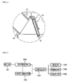
- FIG. 1 is a perspective view illustrating a refrigerator with an ice-making device.
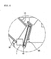
- FIG. 2 is a cross-sectional view illustrating a part of an ice-making device.
- FIG. 3 is a block diagram illustrating configuration of an ice dispensing control system.
- FIGS. 4 to 6 are views illustrating operation of an ice-making device.
- FIG. 7 is a flowchart illustrating a method of controlling an ice-making device.
- FIG. 8 is a flowchart illustrating a method of controlling an ice-making device.
- FIG. 1 illustrates an example of a refrigerator with an ice-making device.
- FIG. 2 illustrates a cross-section of an example of a part of an ice-making device.
- FIG. 3 illustrates an example configuration of an ice dispensing control system.
- a refrigerator compartment 3 and a freezer compartment are disposed in a main body 1.
- the refrigerator compartment 3 and the freezer compartment, where foods are stored, are arranged vertically in the main body 1, with the refrigerator compartment 3 being positioned above the freezer compartment.
- the refrigerator compartment 3 is opened and closed by refrigerator compartment doors 5 and 6 and the freezer compartment is opened and closed by a freezer compartment door 7.
- An ice-making chamber 9 is provided to an inner surface of the refrigerator compartment door 5 (hereinafter, referred to as a "door").
- the ice-making chamber 9 is separated from the refrigerator compartment 3, and an ice-making device (not shown) for making ice is disposed in the ice-making chamber 9.
- a front surface of the door 5 is provided with a dispenser (not shown).
- the dispenser is used to dispense water and/or ice without opening the door 5.
- an ice duct 10 is disposed in the door 5.
- the ice duct 10 is used to dispense ice made by the ice-making device to an outside of the refrigerator, that is, to the outside of the refrigerator through the dispenser which transports ice through the door 5 when the door 5 is in a closed positioned.
- a first end of the ice duct 10 communicates with the ice-making device and a second end of the ice duct 10 communicates with the dispenser.
- a duct cap 20 opens and closes an end of the ice duct 10 adjacent to the dispenser (e.g., the second end of the ice duct 10 that communicates with the dispenser). One end of the duct cap 20 rotates about the other end to open and close the ice duct 10.
- the ice duct 10 and the duct cap 20 are provided with a hall sensor 30 and a magnet 40, respectively.
- the hall sensor 30 and the magnet 40 may be disposed at a position where the ice duct 10 faces the duct cap 20.
- the hall sensor 30 and the magnet 40 sense a position of the duct cap 20 relative to the ice duct 10. More particularly, the hall sensor 30 provided to the ice duct 10 senses strength (e.g., presence or absence) of a magnetic field of the magnet 40 provided to the duct cap 20 and, thereby, senses the position of the duct cap 20 relative to the ice duct 10.
- the hall sensor 30 senses a relatively strong (e.g., a present) magnetic field and detects that the duct cap 20 is in a position to close the ice duct 10.
- the hall sensor 30 senses a relatively weak (e.g., an absent) magnetic field and detects that the duct cap 20 is in a position to open the ice duct 10.
- an input part 100 receives an operation signal for dispensing ice through the dispenser.
- a warning part 200 displays whether the duct cap 20 is in abnormal operation.
- the warning part 200 may display the abnormal operation of the duct cap 20 using a lamp on/off, display of characters or symbols, any type of visual display, or an audible output (e.g., a voice output).
- a cap-driving part 300 provides a driving force for rotating the duct cap 20.
- the cap-driving part 300 may include a solenoid valve or a motor. That is, the cap-driving part 300 rotates in a predetermined direction or a reverse direction, so that the duct cap 20 opens or closes one end of the ice duct 10.
- Current is applied to the cap-driving part 300 to rotate the duct cap 20.
- a starting current is applied during an initial driving of the cap-driving part 300, and a normal operation current or a load operation current is applied while the cap-driving part 300 is driven.
- the normal operation current is a current applied to the cap-driving part 300 when a normal load, that is, a load corresponding to the weight of the duct cap 20 is applied to the cap-driving part 300.
- the load operation current is a current applied to the cap-driving part 300 during an abnormal load, that is when a load added to the weight of the duct cap 20 is applied to the cap-driving part 300, for example, when a foreign substance such as ice is caught between the ice duct 10 and the duct cap 20 during the operation of the duct cap 20, so as to interfere with the normal operation of the duct cap 20.
- the normal operation current is lower than the starting current and the load operation current.
- a current applied when operating the cap-driving part 300 that is, an operation current
- a current-sensing part 400 senses the operation current of the cap-driving part 300 as the starting current.
- the current-sensing part 400 senses the normal operation current or the load operation current as the operation current of the cap-driving part 300 according to a load applied to the duct cap 20.
- a control part 500 controls the dispensing of ice through the dispenser.
- the control part 500 controls the cap-driving part 300 to rotate the duct cap 20 to close or open the ice duct 10 according to an operation signal input to the input part 100.
- the control part 500 controls the cap-driving part 300 such that the duct cap 20 opens the ice duct 10.
- the control part 500 controls the cap-driving part 300 such that the duct cap 20 repeats opening and closing operation of the ice duct 10 at least one time until the duct cap 20 operates normally.
- the abnormal operation of the duct cap 20 is detected when an abnormal load is applied to the duct cap 20 while the duct cap 20 closes the ice duct 10.
- Whether the abnormal load is applied to the duct cap 20 is determined according to whether an operation time for the duct cap 20 to rotate from the position where the duct cap 20 opens the ice duct 10 to the position where the duct cap 20 closes the ice duct 10 is greater than a set time, and/or according to whether an operation current of the cap-driving part 300 sensed by the current-sensing part 400 while the duct cap 20 rotates from the position where the duct cap 20 opens the ice duct 10 to the position where the duct cap 20 closes the ice duct 10 is greater than a preset reference current.
- the reference current may be set at least to the starting current and the load operation current, or more.
- the hall sensor 30 fails to sense that the duct cap 20 arrives at the position where the duct cap 20 closes the ice duct 10 prior to the operation time expiring, or the current-sensing part 400 senses that the operation current of the cap-driving part 300 is greater than the reference current while the duct cap 20 closes the ice duct 10.
- the control part 500 controls the cap-driving part 300 to gradually reduce the operation time of the duct cap 20. For instance, as the repeated number of opening and closing operations of the duct cap 20 for the ice duct 10 increases, possibility that a foreign substance is removed between the ice duct 10 and the duct cap 20 also increases. Thus, gradually reducing the opening and closing time of the duct cap 20 for the ice duct 10 reduces an amount of air in the ice-making device that escapes through the ice duct 10 to the outside by the rotation of the duct cap 20 opening and closing the ice duct 10. In this regard, leakage of cold air from the ice-making chamber may be reduced when attempting to correct abnormal operation of the duct cap 20.
- the control part 500 controls the warning part 200 to provide a warning indicating abnormal operation of the duct cap 20.
- Providing the warning may alert a user to the abnormal operation of the duct cap 20 and, thereby, allow the user to correct the abnormal operation (e.g., remove an ice piece that is preventing the duct cap 20 from closing). This may result in correction of the abnormal operation more quickly and, therefore, reduce an amount of cold air that leaks from the ice-making chamber due to the abnormal operation.
- the set time, the reference current, and the set number of times are stored in a memory part 600 (e.g., a random access memory, read only memory, or any type of electronic storage device) and may be user-configurable.
- the memory part 600 may store the operation times of the duct cap 20 depending on the set number.
- FIGS. 4 to 6 illustrate example operation of an ice-making.
- the input part 100 receives an operation signal for dispensing ice through the dispenser
- the control part 500 controls the cap-driving part 300 (refer to FIG. 3 ) to rotate the duct cap 20 to open the ice duct 10 in response to the operation signal for dispensing ice through the dispenser.
- the ice made at the ice-making device is dispensed through the ice duct 10.
- the hall sensor 30 senses that the magnetic field of the magnet 40 of the duct cap 20 is relatively weak (e.g., absent or less than a threshold), and thus senses that the duct cap 20 is disposed at the position of opening the ice duct 10.
- the current-sensing part 400 (refer to FIG. 3 ) senses the operation current of the cap-driving part 300 as the starting current.
- the control part 500 controls the cap-driving part 300 to rotate the duct cap 20 to close the ice duct 10.
- the ice duct 10 is closed to finish the dispensing of the ice through the ice duct 10.
- the hall sensor 30 senses that the magnetic field of the magnet 40 of the duct cap 20 is relatively strong (e.g., present or greater than a threshold), and thus senses the duct cap 20 is disposed at the position of closing the ice duct 10.
- the current-sensing part 400 senses the operation current of the cap-driving part 300 as the normal operation current.
- the control part 500 controls the cap-driving part 300 such that the duct cap 20 closes the ice duct 10, when an ice piece I is caught between the ice duct 10 and the duct cap 20, the duct cap 20 fails to close the ice duct 10 completely.
- the hall sensor 30 senses that the magnetic field of the magnet 40 of the duct cap 20 is relatively weak (e.g., absent or less than a threshold) and thus senses that the duct cap 20 is not disposed at the position of closing the ice duct 10.
- the current-sensing part 400 senses the operation current of the cap-driving part 300 as an abnormal operation current.
- the control part 500 controls the duct cap 20 to rotate to open the ice duct 10 or controls the duct cap 20 to rotate to open and close the ice duct 10 a set number of times.
- FIG. 7 illustrates an example of a method of controlling an ice-making device.
- the input part 100 receives an operation signal starting the dispensing of ice through the dispenser (S11).
- the input part 100 may receive the operation signal starting the dispensing of the ice through the dispenser by receiving a user's press of an operation button (not shown) or receiving a user's press of a lever (not shown) with a container for receiving ice.
- the control part 500 controls the operation of the cap-driving part 300 such that the duct cap 20 opens the ice duct 10 (S13). After the ice duct 10 is opened by the duct cap 20 (S13), the ice is dispensed through the ice duct 10 (S15).
- whether the dispensing of the ice through the ice duct 10 is finished may be determined according to whether the input part 100 receives an operation signal finishing the dispensing of the ice, according to whether the input part 100 further receives the operation signal for dispensing the ice (e.g., whether a user continues to supply a constant pressing force to a dispensing control button or lever), or according to whether the time for dispensing the ice, set according to the operation signal dispensing the ice and input to the input part 100 is finished.
- the control part 500 controls the operation of the cap-driving part 300 such that the duct cap 20 closes the ice duct 10 (S19).
- the duct cap 20 operates to close the ice duct 10.
- the current-sensing part 400 senses the operation current applied to the cap-driving part 300 (S21). While the duct cap 20 closes the ice duct 10 (S21), it is determined whether the operation current of the cap-driving part 300 sensed by the current-sensing part 400 is greater than the reference current (S23).
- the normal operation current is applied to the cap-driving part 300.
- the duct cap 20 operates normally to close the ice duct 10 and the closing operation of the duct cap 20 completes.
- the control part 500 controls the cap-driving part 300 such that the duct cap 20 opens the ice duct 10 (S25). Then, the control part 500 controls the cap-driving part 300 such that operations associated with reference numerals (S19) to (S23) are repeated.
- FIG. 8 illustrates an example of a method of controlling an ice-making device.
- the input part 100 receives an operation signal starting the dispensing of ice through the dispenser (S31). Then, according to the operation signal input to the input part 100, the control part 500 controls the cap-driving part 300 such that the duct cap 20 opens the ice duct 10 (S33), so that the ice is dispensed through the ice duct 10 (S35).
- the control part 500 controls the cap-driving part 300 such that the duct cap 20 closes the ice duct 10 (S39).
- the current-sensing part 400 senses the operation current of the cap-driving part 300 (S41). Then, it is determined whether the operation current of the cap-driving part 300 sensed by the current-sensing part 400 is greater than the reference current (S43). When it is determined that the operation current of the cap-driving part 300 sensed by the current-sensing part 400 is the reference current or less (S43), the duct cap 20 operates normally to close the ice duct 10, and thus the closing operation of the duct cap 20 completes.
- the control part 500 controls the cap-driving part 300 such that the duct cap 20 opens and closes the ice duct 10 (S45).
- the current-sensing part 400 senses the operation current of the cap-driving part 300 (S47), and it is determined whether the operation current of the cap-driving part 300 sensed by the current-sensing part 400 is greater than the reference current (S49).
- the duct cap 20 When it is determined that the operation current of the cap-driving part 300 sensed by the current-sensing part 400 is the reference current or less (S49), the duct cap 20 operates normally to close the ice duct 10, and thus the closing operation of the duct cap 20 completes.
- the control part 500 controls the cap-driving part 300 such that operations associated with reference numerals (S45) to (S51) are repeated.
- the control part 500 controls the warning part 200 to warn about abnormal operation of the duct cap 20 (S53).
- the warning part 200 may warn through a lamp on/off, display of characters or symbols, any type of visual display, or (e.g., a voice output).
- the ice-making device has been described as being installed in the ice-making chamber disposed on a back surface of the refrigerator compartment door, the present disclosure is not limited thereto.
- the ice-making device may be installed in an ice-making chamber located inside of the refrigerator compartment door (e.g., within a storage space defined by the refrigerator compartment and separate from the door).
- the ice-making device may be installed on a back surface of a freezer compartment door or located inside of the freezer compartment door (e.g., within a storage space defined by the freezer compartment and separate from the door).
- the duct cap 20 is not limited to a rotating operation to open or close the ice duct.
- the duct cap may be translated (e.g., slid) to open or close the ice duct.
- the ice duct is a member for dispensing the ice
- the duct cap is a member for opening or closing the member for dispensing the ice.
- times in which the duct cap fails to close the ice duct because of ice caught between the ice duct and the duct cap may be reduced. This makes it possible to reduce cool air in the refrigerator compartment and the ice-making chamber from being discharged through the ice duct to the outside.
- a user may be warned when the duct cap fails to close the ice duct completely even when the operation of the duct cap for opening and closing the ice duct is performed a plurality of times.
- the user can remove ice between the ice duct and the duct cap. This may improve operation reliability and efficiency of the dispenser.
Landscapes
- Engineering & Computer Science (AREA)
- Physics & Mathematics (AREA)
- Mechanical Engineering (AREA)
- Thermal Sciences (AREA)
- General Engineering & Computer Science (AREA)
- Production, Working, Storing, Or Distribution Of Ice (AREA)
- Devices That Are Associated With Refrigeration Equipment (AREA)
- Packging For Living Organisms, Food Or Medicinal Products That Are Sensitive To Environmental Conditiond (AREA)
Claims (13)
- Eisbereitungsvonichtung, die Folgendes umfasst:- einen Schacht (10), durch den Eis ausgegeben wird;- ein Schachtabdeckungsbauteil (20), das den Schacht (10) öffnet und schließt; und- ein Steuerungsbauteil (500), das konfiguriert ist, das Schachtabdeckungsbauteil (20) zu steuern,dadurch gekennzeichnet, dass das Steuerungsbauteil (500) konfiguriert ist, festzustellen, ob eine Betriebslast, die auf das Schachtabdeckungsbauteil (20), wenn das Schachtabdeckungsbauteil (20) versucht, den Schacht (10) zu schließen, aufgebracht wird, größer als eine voreingestellte Normallast ist, und das konfiguriert ist, das Schachtabdeckungsbauteil (20) zu steuern, den Schacht (10) in Reaktion auf die Feststellung, dass die auf das Schachtabdeckungsbauteil (20) aufgebrachte Betriebslast, wenn das Schachtabdeckungsbauteil (20) versucht, den Schacht (10) zu schließen, größer als die voreingestellte Normallast ist, zu öffnen.
- Eisbereitungsvorrichtung nach Anspruch 1, wobei das Steuerungsbauteil (500) in Übereinstimmung damit, ob eine Betriebszeit für das Schachtabdeckungsbauteil (20) zum Schließen des Schachts (10) länger als eine voreingestellte normale Zeit ist, die zum Schließen des Schachts (10) erforderlich ist, feststellt, ob die Betriebslast größer als die Normallast ist.
- Eisbereitungsvorrichtung nach Anspruch 1 oder 2, wobei das Steuerungsbauteil (500), falls die Betriebslast größer als die voreingestellte Normallast ist, das Schachtabdeckungsbauteil (20) steuert, zum Öffnen und Schließen des Schachts (10) wenigstens einmal zu arbeiten, bis die Betriebslast die Normallast erreicht.
- Eisbereitungsvorrichtung nach Anspruch 1, wobei das Steuerungsbauteil (500) in Übereinstimmung damit, ob ein Betriebsstrom, der durch das Schachtabdeckungsbauteil (20) geschickt wird, um den Schacht (10) zu schließen, größer als ein voreingestellter Bezugsstrom ist, feststellt, ob die Betriebslast größer als die Normallast ist.
- Eisbereitungsvorrichtung nach Anspruch 4, wobei der Bezugsstrom wenigstens auf einen Startstrom und auf einen voreingestellten Normalbetriebsstrom eingestellt ist, und wobei der Startstrom durch das Schachtabdeckungsbauteil (20) geschickt wird, wenn das Schachtabdeckungsbauteil (20) in einem Startbetrieb ist, und wobei der voreingestellte Normalbetriebsstrom durch das Schachtabdeckungsbauteil (20) geschickt wird, um den Schacht (10) zu schließen.
- Eisbereitungsvorrichtung nach Anspruch 4 oder 5, wobei das Steuerungsbauteil (500) dann, wenn der Betriebsstrom größer als der Bezugsstrom ist, das Schachtabdeckungsbauteil (20) steuert, zum Öffnen und Schließen des Schachts (10) wenigstens einmal zu arbeiten, bis der Betriebsstrom den Bezugsstrom erreicht.
- Eisbereitungsvorrichtung nach Anspruch 6, die ferner ein Warnungsbauteil umfasst, das konfiguriert ist, eine Warnung für einen Benutzer in einem Fall auszugeben, in dem der Betriebsstrom größer als der Bezugsstrom ist, auch wenn das Schachtabdeckungsbauteil (20) in einer im Voraus eingestellten Anzahl wiederholt arbeitet ist, um den Schacht (10) zu schließen und zu öffnen.
- Verfahren zum Steuern einer Eisbereitungsvorrichtung, das die folgenden Schritte umfasst:- Öffnen eines Schachts (10) zum Ausgeben von Eis durch Steuern eines Schachtabdeckungsbauteils (20) in einem Steuerungsbauteil (500);- Schließen des Schachts durch Steuern des Schachtabdeckungsbauteils (20) in einem Steuerungsbauteil (500) nach dem Ausgeben des Eises, so dass dieses in Betrieb ist;dadurch gekennzeichnet, dass das Verfahren ferner den folgenden Schritt umfasst:- erneutes Öffnen des Schachts (10), wenn eine Betriebslast, die auf das Schachtabdeckungsbauteil (20) aufgebracht wird, größer als eine voreingestellte Normallast beim Schließen des Schachts (10) ist.
- Verfahren nach Anspruch 8, das ferner ein erneutes Schließen des Schachts (10) durch Betätigen des Schachtabdeckungsbauteils (20) umfasst, um den Schacht (10) nach dem erneuten Öffnen des Schachts (10) zu schließen.
- Verfahren nach Anspruch 9, wobei das erneute Öffnen des Schachts (10) und das erneute Schließen des Schachts (10) wiederholt werden, bis die Betriebslast die Normallast erreicht, während das Schachtabdeckungsbauteil (20) den Schacht (10) schließt.
- Verfahren nach Anspruch 9, das ferner das Warnen eines Benutzers vor einem Fall umfasst, bei dem die Betriebslast größer als die Normallast ist, auch wenn das erneute Öffnen des Schachts (10) und das erneute Schließen des Schachts (10) in einer im Voraus eingestellten Anzahl wiederholt werden, wenn dieser Fall eintritt.
- Verfahren nach einem der Ansprüche 8 bis 11, wobei in Übereinstimmung damit, ob ein Betriebsstrom, der durch das Schachtabdeckungsbauteil (20) geschickt wird, um den Schacht (10) zu schließen, größer als ein voreingestellter Bezugsstrom ist, festgestellt wird, ob bei dem erneuten Öffnen des Schachts (10) die Betriebslast größer als die Normallast ist.
- Verfahren nach Anspruch 12, wobei in Übereinstimmung damit, ob der Betriebsstrom, der durch ein Sensorbauteil (400) gemessen und durch das Schachtabdeckungsbauteil (20) geschickt wird, größer als ein Startstrom und ein voreingestellter Normalbetriebsstrom ist, festgestellt wird, ob bei dem erneuten Öffnen des Schachts (10) der Betriebsstrom größer als der Bezugsstrom ist, und wobei der Startstrom durch das Schachtabdeckungsbauteil (20) geschickt wird, wenn das Schachtabdeckungsbauteil (20) in einem Startbetrieb ist, und wobei der voreingestellte Normalbetriebsstrom durch das Schachtabdeckungsbauteil (20) geschickt wird, um den Schacht (10) zu schließen.
Applications Claiming Priority (1)
| Application Number | Priority Date | Filing Date | Title |
|---|---|---|---|
| KR1020080113687A KR101545022B1 (ko) | 2008-11-14 | 2008-11-14 | 제빙장치 및 그 제어방법 |
Publications (3)
| Publication Number | Publication Date |
|---|---|
| EP2187152A2 EP2187152A2 (de) | 2010-05-19 |
| EP2187152A3 EP2187152A3 (de) | 2011-06-01 |
| EP2187152B1 true EP2187152B1 (de) | 2015-11-11 |
Family
ID=41675701
Family Applications (1)
| Application Number | Title | Priority Date | Filing Date |
|---|---|---|---|
| EP09008458.3A Not-in-force EP2187152B1 (de) | 2008-11-14 | 2009-06-29 | Eisspendetechnologie |
Country Status (4)
| Country | Link |
|---|---|
| US (1) | US8333306B2 (de) |
| EP (1) | EP2187152B1 (de) |
| KR (1) | KR101545022B1 (de) |
| CN (1) | CN101738039B (de) |
Cited By (1)
| Publication number | Priority date | Publication date | Assignee | Title |
|---|---|---|---|---|
| US20240191927A1 (en) * | 2022-12-13 | 2024-06-13 | Marmon Foodservice Technologies, Inc. | Ice dispensers |
Families Citing this family (2)
| Publication number | Priority date | Publication date | Assignee | Title |
|---|---|---|---|---|
| KR101545022B1 (ko) | 2008-11-14 | 2015-08-17 | 엘지전자 주식회사 | 제빙장치 및 그 제어방법 |
| US9772135B2 (en) * | 2013-09-25 | 2017-09-26 | Whirlpool Corporation | Refrigerator dispenser with a feedback signal |
Family Cites Families (27)
| Publication number | Priority date | Publication date | Assignee | Title |
|---|---|---|---|---|
| DE2926938A1 (de) * | 1979-07-04 | 1981-01-22 | Rau Swf Autozubehoer | Schaltanordnung zum antrieb eines beweglichen elementes, insbesondere zum antrieb von scheiben o.dgl. in kraftfahrzeugen |
| JPS56123783A (en) * | 1980-02-29 | 1981-09-29 | Nippon Denso Co Ltd | Control unit for load driving |
| JPS5719483A (en) * | 1980-07-09 | 1982-02-01 | Hitachi Ltd | Automatic door operator |
| US4701684A (en) * | 1984-11-26 | 1987-10-20 | Automatic Roller Doors Australia Pty. Ltd. | Door or gate obstruction control |
| US4739233A (en) * | 1987-07-31 | 1988-04-19 | Whirlpool Corporation | Motor control for an ice dispensing apparatus |
| NZ248935A (en) * | 1992-11-02 | 1995-10-26 | White Consolidated Ind Inc | Refrigerator door ice dispenser: actuator dimensioned to accommodate polystyrene cup |
| KR0177738B1 (ko) * | 1996-06-10 | 1999-04-15 | 윤종용 | 자동제빙기의 이빙모드 제어방법 |
| JP3112450B2 (ja) * | 1998-03-03 | 2000-11-27 | 三星電子株式会社 | 冷蔵庫のアイスディスペンサー |
| US20070011924A1 (en) | 2003-01-23 | 2007-01-18 | Imm Technologies Ltd. | Multi Image Display Device |
| US20050009848A1 (en) | 2003-07-10 | 2005-01-13 | Icn Pharmaceuticals Switzerland Ltd. | Use of antivirals against inflammatory bowel diseases |
| ITGE20030084A1 (it) | 2003-10-29 | 2005-04-30 | Carpigiani Group Ali Spa | Macchina combinata per la fabbricazione sia di gelati |
| KR20060053212A (ko) | 2004-09-30 | 2006-05-19 | 삼성전자주식회사 | 냉장고 |
| KR100690671B1 (ko) | 2005-03-11 | 2007-03-09 | 엘지전자 주식회사 | 냉장고의 아이스빈 |
| KR100719024B1 (ko) | 2005-11-14 | 2007-05-17 | 삼성전자주식회사 | 냉장고 및 그 제어방법 |
| KR100737956B1 (ko) * | 2005-11-29 | 2007-07-13 | 삼성전자주식회사 | 냉장고 |
| US20070251259A1 (en) * | 2006-04-28 | 2007-11-01 | Lg Electronics Inc. | Ice-making device for refrigerator and control method thereof |
| US20070256442A1 (en) * | 2006-05-03 | 2007-11-08 | Viking Range Corporation | Motorized ice dispenser door |
| KR101275564B1 (ko) * | 2006-09-08 | 2013-06-14 | 엘지전자 주식회사 | 냉장고 |
| KR100820818B1 (ko) * | 2006-11-13 | 2008-04-11 | 엘지전자 주식회사 | 디스펜싱 장치 및 이를 이용한 냉장고 |
| US7797961B2 (en) * | 2006-12-07 | 2010-09-21 | Samsung Electronics Co., Ltd. | Refrigerator having improved ice-making unit configuration |
| US7942016B2 (en) * | 2006-12-28 | 2011-05-17 | Whirlpool Corporation | Icemaker external intrusion protection |
| KR20080065435A (ko) | 2007-01-09 | 2008-07-14 | 엘지전자 주식회사 | 냉장고용 얼음안내장치 |
| DE102007048574A1 (de) * | 2007-10-10 | 2009-04-16 | BSH Bosch und Siemens Hausgeräte GmbH | Eisspender |
| DE102008013750A1 (de) * | 2008-03-12 | 2009-09-24 | Emz-Hanauer Gmbh & Co. Kgaa | Eisklappenvorrichtung für einen Kühlschrank |
| KR101552722B1 (ko) * | 2008-11-14 | 2015-09-11 | 엘지전자 주식회사 | 제빙장치 및 그 제어방법 |
| KR101545022B1 (ko) | 2008-11-14 | 2015-08-17 | 엘지전자 주식회사 | 제빙장치 및 그 제어방법 |
| US8067915B2 (en) * | 2008-12-31 | 2011-11-29 | General Electric Company | Electronic control circuit for a powered appliance drawer |
-
2008
- 2008-11-14 KR KR1020080113687A patent/KR101545022B1/ko active Active
-
2009
- 2009-06-22 US US12/488,636 patent/US8333306B2/en active Active
- 2009-06-29 EP EP09008458.3A patent/EP2187152B1/de not_active Not-in-force
- 2009-07-10 CN CN2009101401893A patent/CN101738039B/zh active Active
Cited By (1)
| Publication number | Priority date | Publication date | Assignee | Title |
|---|---|---|---|---|
| US20240191927A1 (en) * | 2022-12-13 | 2024-06-13 | Marmon Foodservice Technologies, Inc. | Ice dispensers |
Also Published As
| Publication number | Publication date |
|---|---|
| US20100122751A1 (en) | 2010-05-20 |
| KR20100054680A (ko) | 2010-05-25 |
| EP2187152A2 (de) | 2010-05-19 |
| CN101738039B (zh) | 2012-01-04 |
| US8333306B2 (en) | 2012-12-18 |
| KR101545022B1 (ko) | 2015-08-17 |
| EP2187152A3 (de) | 2011-06-01 |
| CN101738039A (zh) | 2010-06-16 |
Similar Documents
| Publication | Publication Date | Title |
|---|---|---|
| EP2187153B1 (de) | Eisausgabetechnologie | |
| EP2187151B1 (de) | Eisspendetechnologie | |
| US8196426B2 (en) | Refrigerator dispenser control technology | |
| US20020083726A1 (en) | Ice maker for refrigerator and control method therof | |
| KR101668251B1 (ko) | 냉장고 및 그 동작방법 | |
| KR20090115307A (ko) | 냉장고 제빙기의 만빙 감지 장치 및 그 만빙 감지 방법 | |
| EP2187152B1 (de) | Eisspendetechnologie | |
| KR101995426B1 (ko) | 냉장고 및 그 제어 방법 | |
| EP2357436B1 (de) | Kühlschrank und betriebsverfahren | |
| US8365548B2 (en) | Ice dispensing technology | |
| EP1429092B1 (de) | Kühlschrank mit einer Eisabgabevorrichtung | |
| JP4629811B2 (ja) | 製氷機 | |
| KR20090020185A (ko) | 냉장고 및 그의 제어방법 | |
| KR100301636B1 (ko) | 냉장고자동제빙기의급수제어방법 | |
| KR100633433B1 (ko) | 소비전력 저감형 자동판매기 및 그 제어방법 | |
| JPH10300309A (ja) | 冷蔵庫 | |
| KR200215356Y1 (ko) | 구슬형 아이스크림 자동판매기의 원료 매진감지장치 | |
| JPH0684059A (ja) | 自動販売機の冷却制御装置 | |
| KR20010002582A (ko) | 냉장고의 급수장치 및 그 제어방법 | |
| KR19980073774A (ko) | 아이스크림 자동판매기 | |
| KR20060027914A (ko) | 냉장고 및 제빙장치 고장판단방법 | |
| KR19980017942A (ko) | 냉장고의 음료공급장치 | |
| KR20050017309A (ko) | 냉장고 및 그 제어 방법 | |
| JPH1038432A (ja) | 冷凍冷蔵庫のダンパ装置 | |
| KR20000041067A (ko) | 자동제빙기의 정량급수장치 |
Legal Events
| Date | Code | Title | Description |
|---|---|---|---|
| PUAI | Public reference made under article 153(3) epc to a published international application that has entered the european phase |
Free format text: ORIGINAL CODE: 0009012 |
|
| AK | Designated contracting states |
Kind code of ref document: A2 Designated state(s): AT BE BG CH CY CZ DE DK EE ES FI FR GB GR HR HU IE IS IT LI LT LU LV MC MK MT NL NO PL PT RO SE SI SK TR |
|
| AX | Request for extension of the european patent |
Extension state: AL BA RS |
|
| PUAL | Search report despatched |
Free format text: ORIGINAL CODE: 0009013 |
|
| AK | Designated contracting states |
Kind code of ref document: A3 Designated state(s): AT BE BG CH CY CZ DE DK EE ES FI FR GB GR HR HU IE IS IT LI LT LU LV MC MK MT NL NO PL PT RO SE SI SK TR |
|
| AX | Request for extension of the european patent |
Extension state: AL BA RS |
|
| 17P | Request for examination filed |
Effective date: 20111103 |
|
| GRAP | Despatch of communication of intention to grant a patent |
Free format text: ORIGINAL CODE: EPIDOSNIGR1 |
|
| INTG | Intention to grant announced |
Effective date: 20150602 |
|
| RAP1 | Party data changed (applicant data changed or rights of an application transferred) |
Owner name: LG ELECTRONICS INC. |
|
| GRAS | Grant fee paid |
Free format text: ORIGINAL CODE: EPIDOSNIGR3 |
|
| GRAA | (expected) grant |
Free format text: ORIGINAL CODE: 0009210 |
|
| AK | Designated contracting states |
Kind code of ref document: B1 Designated state(s): AT BE BG CH CY CZ DE DK EE ES FI FR GB GR HR HU IE IS IT LI LT LU LV MC MK MT NL NO PL PT RO SE SI SK TR |
|
| REG | Reference to a national code |
Ref country code: GB Ref legal event code: FG4D |
|
| REG | Reference to a national code |
Ref country code: CH Ref legal event code: EP |
|
| REG | Reference to a national code |
Ref country code: IE Ref legal event code: FG4D |
|
| REG | Reference to a national code |
Ref country code: AT Ref legal event code: REF Ref document number: 760666 Country of ref document: AT Kind code of ref document: T Effective date: 20151215 |
|
| REG | Reference to a national code |
Ref country code: DE Ref legal event code: R096 Ref document number: 602009034728 Country of ref document: DE |
|
| REG | Reference to a national code |
Ref country code: LT Ref legal event code: MG4D |
|
| REG | Reference to a national code |
Ref country code: NL Ref legal event code: MP Effective date: 20160211 |
|
| REG | Reference to a national code |
Ref country code: AT Ref legal event code: MK05 Ref document number: 760666 Country of ref document: AT Kind code of ref document: T Effective date: 20151111 |
|
| PG25 | Lapsed in a contracting state [announced via postgrant information from national office to epo] |
Ref country code: NL Free format text: LAPSE BECAUSE OF FAILURE TO SUBMIT A TRANSLATION OF THE DESCRIPTION OR TO PAY THE FEE WITHIN THE PRESCRIBED TIME-LIMIT Effective date: 20151111 Ref country code: LT Free format text: LAPSE BECAUSE OF FAILURE TO SUBMIT A TRANSLATION OF THE DESCRIPTION OR TO PAY THE FEE WITHIN THE PRESCRIBED TIME-LIMIT Effective date: 20151111 Ref country code: NO Free format text: LAPSE BECAUSE OF FAILURE TO SUBMIT A TRANSLATION OF THE DESCRIPTION OR TO PAY THE FEE WITHIN THE PRESCRIBED TIME-LIMIT Effective date: 20160211 Ref country code: IS Free format text: LAPSE BECAUSE OF FAILURE TO SUBMIT A TRANSLATION OF THE DESCRIPTION OR TO PAY THE FEE WITHIN THE PRESCRIBED TIME-LIMIT Effective date: 20160311 Ref country code: IT Free format text: LAPSE BECAUSE OF FAILURE TO SUBMIT A TRANSLATION OF THE DESCRIPTION OR TO PAY THE FEE WITHIN THE PRESCRIBED TIME-LIMIT Effective date: 20151111 Ref country code: ES Free format text: LAPSE BECAUSE OF FAILURE TO SUBMIT A TRANSLATION OF THE DESCRIPTION OR TO PAY THE FEE WITHIN THE PRESCRIBED TIME-LIMIT Effective date: 20151111 Ref country code: HR Free format text: LAPSE BECAUSE OF FAILURE TO SUBMIT A TRANSLATION OF THE DESCRIPTION OR TO PAY THE FEE WITHIN THE PRESCRIBED TIME-LIMIT Effective date: 20151111 |
|
| REG | Reference to a national code |
Ref country code: FR Ref legal event code: PLFP Year of fee payment: 8 |
|
| PG25 | Lapsed in a contracting state [announced via postgrant information from national office to epo] |
Ref country code: PL Free format text: LAPSE BECAUSE OF FAILURE TO SUBMIT A TRANSLATION OF THE DESCRIPTION OR TO PAY THE FEE WITHIN THE PRESCRIBED TIME-LIMIT Effective date: 20151111 Ref country code: LV Free format text: LAPSE BECAUSE OF FAILURE TO SUBMIT A TRANSLATION OF THE DESCRIPTION OR TO PAY THE FEE WITHIN THE PRESCRIBED TIME-LIMIT Effective date: 20151111 Ref country code: SE Free format text: LAPSE BECAUSE OF FAILURE TO SUBMIT A TRANSLATION OF THE DESCRIPTION OR TO PAY THE FEE WITHIN THE PRESCRIBED TIME-LIMIT Effective date: 20151111 Ref country code: PT Free format text: LAPSE BECAUSE OF FAILURE TO SUBMIT A TRANSLATION OF THE DESCRIPTION OR TO PAY THE FEE WITHIN THE PRESCRIBED TIME-LIMIT Effective date: 20160311 Ref country code: FI Free format text: LAPSE BECAUSE OF FAILURE TO SUBMIT A TRANSLATION OF THE DESCRIPTION OR TO PAY THE FEE WITHIN THE PRESCRIBED TIME-LIMIT Effective date: 20151111 Ref country code: GR Free format text: LAPSE BECAUSE OF FAILURE TO SUBMIT A TRANSLATION OF THE DESCRIPTION OR TO PAY THE FEE WITHIN THE PRESCRIBED TIME-LIMIT Effective date: 20160212 Ref country code: AT Free format text: LAPSE BECAUSE OF FAILURE TO SUBMIT A TRANSLATION OF THE DESCRIPTION OR TO PAY THE FEE WITHIN THE PRESCRIBED TIME-LIMIT Effective date: 20151111 |
|
| PG25 | Lapsed in a contracting state [announced via postgrant information from national office to epo] |
Ref country code: CZ Free format text: LAPSE BECAUSE OF FAILURE TO SUBMIT A TRANSLATION OF THE DESCRIPTION OR TO PAY THE FEE WITHIN THE PRESCRIBED TIME-LIMIT Effective date: 20151111 |
|
| REG | Reference to a national code |
Ref country code: DE Ref legal event code: R097 Ref document number: 602009034728 Country of ref document: DE |
|
| PG25 | Lapsed in a contracting state [announced via postgrant information from national office to epo] |
Ref country code: EE Free format text: LAPSE BECAUSE OF FAILURE TO SUBMIT A TRANSLATION OF THE DESCRIPTION OR TO PAY THE FEE WITHIN THE PRESCRIBED TIME-LIMIT Effective date: 20151111 Ref country code: DK Free format text: LAPSE BECAUSE OF FAILURE TO SUBMIT A TRANSLATION OF THE DESCRIPTION OR TO PAY THE FEE WITHIN THE PRESCRIBED TIME-LIMIT Effective date: 20151111 Ref country code: RO Free format text: LAPSE BECAUSE OF FAILURE TO SUBMIT A TRANSLATION OF THE DESCRIPTION OR TO PAY THE FEE WITHIN THE PRESCRIBED TIME-LIMIT Effective date: 20151111 Ref country code: SK Free format text: LAPSE BECAUSE OF FAILURE TO SUBMIT A TRANSLATION OF THE DESCRIPTION OR TO PAY THE FEE WITHIN THE PRESCRIBED TIME-LIMIT Effective date: 20151111 |
|
| PLBE | No opposition filed within time limit |
Free format text: ORIGINAL CODE: 0009261 |
|
| STAA | Information on the status of an ep patent application or granted ep patent |
Free format text: STATUS: NO OPPOSITION FILED WITHIN TIME LIMIT |
|
| 26N | No opposition filed |
Effective date: 20160812 |
|
| PG25 | Lapsed in a contracting state [announced via postgrant information from national office to epo] |
Ref country code: SI Free format text: LAPSE BECAUSE OF FAILURE TO SUBMIT A TRANSLATION OF THE DESCRIPTION OR TO PAY THE FEE WITHIN THE PRESCRIBED TIME-LIMIT Effective date: 20151111 |
|
| PG25 | Lapsed in a contracting state [announced via postgrant information from national office to epo] |
Ref country code: BE Free format text: LAPSE BECAUSE OF FAILURE TO SUBMIT A TRANSLATION OF THE DESCRIPTION OR TO PAY THE FEE WITHIN THE PRESCRIBED TIME-LIMIT Effective date: 20151111 |
|
| PG25 | Lapsed in a contracting state [announced via postgrant information from national office to epo] |
Ref country code: MC Free format text: LAPSE BECAUSE OF FAILURE TO SUBMIT A TRANSLATION OF THE DESCRIPTION OR TO PAY THE FEE WITHIN THE PRESCRIBED TIME-LIMIT Effective date: 20151111 |
|
| REG | Reference to a national code |
Ref country code: CH Ref legal event code: PL |
|
| REG | Reference to a national code |
Ref country code: IE Ref legal event code: MM4A |
|
| PG25 | Lapsed in a contracting state [announced via postgrant information from national office to epo] |
Ref country code: CH Free format text: LAPSE BECAUSE OF NON-PAYMENT OF DUE FEES Effective date: 20160630 Ref country code: LI Free format text: LAPSE BECAUSE OF NON-PAYMENT OF DUE FEES Effective date: 20160630 |
|
| REG | Reference to a national code |
Ref country code: FR Ref legal event code: PLFP Year of fee payment: 9 |
|
| PG25 | Lapsed in a contracting state [announced via postgrant information from national office to epo] |
Ref country code: IE Free format text: LAPSE BECAUSE OF NON-PAYMENT OF DUE FEES Effective date: 20160629 |
|
| REG | Reference to a national code |
Ref country code: FR Ref legal event code: PLFP Year of fee payment: 10 |
|
| PG25 | Lapsed in a contracting state [announced via postgrant information from national office to epo] |
Ref country code: CY Free format text: LAPSE BECAUSE OF FAILURE TO SUBMIT A TRANSLATION OF THE DESCRIPTION OR TO PAY THE FEE WITHIN THE PRESCRIBED TIME-LIMIT Effective date: 20151111 Ref country code: HU Free format text: LAPSE BECAUSE OF FAILURE TO SUBMIT A TRANSLATION OF THE DESCRIPTION OR TO PAY THE FEE WITHIN THE PRESCRIBED TIME-LIMIT; INVALID AB INITIO Effective date: 20090629 |
|
| PG25 | Lapsed in a contracting state [announced via postgrant information from national office to epo] |
Ref country code: TR Free format text: LAPSE BECAUSE OF FAILURE TO SUBMIT A TRANSLATION OF THE DESCRIPTION OR TO PAY THE FEE WITHIN THE PRESCRIBED TIME-LIMIT Effective date: 20151111 Ref country code: LU Free format text: LAPSE BECAUSE OF NON-PAYMENT OF DUE FEES Effective date: 20160629 Ref country code: MK Free format text: LAPSE BECAUSE OF FAILURE TO SUBMIT A TRANSLATION OF THE DESCRIPTION OR TO PAY THE FEE WITHIN THE PRESCRIBED TIME-LIMIT Effective date: 20151111 Ref country code: MT Free format text: LAPSE BECAUSE OF NON-PAYMENT OF DUE FEES Effective date: 20160630 |
|
| PG25 | Lapsed in a contracting state [announced via postgrant information from national office to epo] |
Ref country code: BG Free format text: LAPSE BECAUSE OF FAILURE TO SUBMIT A TRANSLATION OF THE DESCRIPTION OR TO PAY THE FEE WITHIN THE PRESCRIBED TIME-LIMIT Effective date: 20151111 |
|
| PGFP | Annual fee paid to national office [announced via postgrant information from national office to epo] |
Ref country code: GB Payment date: 20240507 Year of fee payment: 16 |
|
| PGFP | Annual fee paid to national office [announced via postgrant information from national office to epo] |
Ref country code: DE Payment date: 20240507 Year of fee payment: 16 |
|
| PGFP | Annual fee paid to national office [announced via postgrant information from national office to epo] |
Ref country code: FR Payment date: 20240508 Year of fee payment: 16 |
|
| REG | Reference to a national code |
Ref country code: DE Ref legal event code: R119 Ref document number: 602009034728 Country of ref document: DE |
|
| GBPC | Gb: european patent ceased through non-payment of renewal fee |
Effective date: 20250629 |
|
| PG25 | Lapsed in a contracting state [announced via postgrant information from national office to epo] |
Ref country code: GB Free format text: LAPSE BECAUSE OF NON-PAYMENT OF DUE FEES Effective date: 20250629 |
|
| PG25 | Lapsed in a contracting state [announced via postgrant information from national office to epo] |
Ref country code: DE Free format text: LAPSE BECAUSE OF NON-PAYMENT OF DUE FEES Effective date: 20260101 |
|
| PG25 | Lapsed in a contracting state [announced via postgrant information from national office to epo] |
Ref country code: FR Free format text: LAPSE BECAUSE OF NON-PAYMENT OF DUE FEES Effective date: 20250630 |