EP2187226B1 - Appareil capteur matriciel à ultra-haute fréquence de décharge partielle pour appareil électrique haute tension - Google Patents
Appareil capteur matriciel à ultra-haute fréquence de décharge partielle pour appareil électrique haute tension Download PDFInfo
- Publication number
- EP2187226B1 EP2187226B1 EP09171456.8A EP09171456A EP2187226B1 EP 2187226 B1 EP2187226 B1 EP 2187226B1 EP 09171456 A EP09171456 A EP 09171456A EP 2187226 B1 EP2187226 B1 EP 2187226B1
- Authority
- EP
- European Patent Office
- Prior art keywords
- signal
- unit
- partial discharge
- ultra
- sensor
- Prior art date
- Legal status (The legal status is an assumption and is not a legal conclusion. Google has not performed a legal analysis and makes no representation as to the accuracy of the status listed.)
- Active
Links
Images


Classifications
-
- G—PHYSICS
- G01—MEASURING; TESTING
- G01R—MEASURING ELECTRIC VARIABLES; MEASURING MAGNETIC VARIABLES
- G01R31/00—Arrangements for testing electric properties; Arrangements for locating electric faults; Arrangements for electrical testing characterised by what is being tested not provided for elsewhere
- G01R31/12—Testing dielectric strength or breakdown voltage ; Testing or monitoring effectiveness or level of insulation, e.g. of a cable or of an apparatus, for example using partial discharge measurements; Electrostatic testing
- G01R31/1227—Testing dielectric strength or breakdown voltage ; Testing or monitoring effectiveness or level of insulation, e.g. of a cable or of an apparatus, for example using partial discharge measurements; Electrostatic testing of components, parts or materials
-
- G—PHYSICS
- G01—MEASURING; TESTING
- G01R—MEASURING ELECTRIC VARIABLES; MEASURING MAGNETIC VARIABLES
- G01R31/00—Arrangements for testing electric properties; Arrangements for locating electric faults; Arrangements for electrical testing characterised by what is being tested not provided for elsewhere
- G01R31/12—Testing dielectric strength or breakdown voltage ; Testing or monitoring effectiveness or level of insulation, e.g. of a cable or of an apparatus, for example using partial discharge measurements; Electrostatic testing
-
- G—PHYSICS
- G01—MEASURING; TESTING
- G01R—MEASURING ELECTRIC VARIABLES; MEASURING MAGNETIC VARIABLES
- G01R29/00—Arrangements for measuring or indicating electric quantities not covered by groups G01R19/00 - G01R27/00
- G01R29/08—Measuring electromagnetic field characteristics
- G01R29/0864—Measuring electromagnetic field characteristics characterised by constructional or functional features
- G01R29/0878—Sensors; antennas; probes; detectors
Definitions
- the present invention relates to an ultra-high frequency partial discharge array sensor apparatus, and more particularly, to an ultra-high frequency partial discharge array sensor apparatus for detecting an electromagnetic wave partial discharge signal generated due to an internal defect of a high-voltage power apparatus such as a gas insulated switchgear, a power transformer, a reactor, or a high voltage rotating machine, in which a high sensitivity sensor for precisely measuring the amplitude of a discharge signal and a plurality of array sensors disposed at regular intervals are integrated as one body, thus measuring the position of an internal defect while detecting a discharge signal.
- a high-voltage power apparatus such as a gas insulated switchgear, a power transformer, a reactor, or a high voltage rotating machine
- the ultra-high frequency partial discharge array sensor apparatus for a high-voltage power apparatus of the invention can eliminate the inconvenience of using a plurality of sensors which are to be installed on a housing of the high-voltage power apparatus to measuring a discharge position while detecting a partial discharge generated due to the internal defect and increase the accuracy of measuring the position of the internal defect by providing accurate coordinates of individual sensors.
- An ultra-high frequency partial discharge sensor is usually used to detect an electromagnetic wave partial discharge signal generated due to an internal defect of a high-voltage power apparatus such as a gas insulated switchgear, a power transformer, a reactor, or a high-voltage rotating machine.
- a high-voltage power apparatus such as a gas insulated switchgear, a power transformer, a reactor, or a high-voltage rotating machine.
- the ultra-high frequency partial discharge sensor has a structure in which a signal detected by one sensing unit with one sensor is transmitted to a measurement apparatus through a connector.
- a signal detected by one sensing unit with one sensor is transmitted to a measurement apparatus through a connector.
- at least two or three ultra-high frequency partial discharge sensors of the same type have to be installed.
- the position where the partial discharge signal is generated is measured by a method such as time difference of arrival (TDOA).
- TDOA time difference of arrival
- a narrow band sensor in which a detection frequency band of the ultra-high frequency partial discharge sensor is narrow is used.
- a signal corresponding to a detection band of the sensor is neither generated nor transmitted depending on the type of a discharge generated in the power apparatus or the position of an internal structure, it is difficult to detect the signal.
- a rising time of a detected signal is not fast, it is not easy to accurately measure a signal arrival time, and thus it is difficult to use the narrow band sensor to measure the internal position of the defect in the power apparatus.
- JPH06105439A KR20070102812 , US6333715B1 , US5506511A , US2007/139056A1 , JPH10170591A , and JPH04372881A .
- the present invention is directed to an ultra-high frequency partial discharge array sensor apparatus for detecting an electromagnetic wave partial discharge signal generated due to an internal defect of a high-voltage power apparatus such as a gas insulated switchgear, a power transformer, a reactor, or a high voltage rotating machine, in which a high sensitivity sensor for precisely measuring the amplitude of a discharge signal and a plurality of array sensors disposed at regular intervals are integrated as one body, thus measuring a position of an internal defect while detecting a discharge signal.
- a high-voltage power apparatus such as a gas insulated switchgear, a power transformer, a reactor, or a high voltage rotating machine
- the present invention is also directed to an ultra-high frequency partial discharge array sensor apparatus for a high-voltage power apparatus, which can eliminate the inconvenience of using a plurality of sensors which are to be installed on a housing of the high-voltage apparatus to measure a discharge position while detecting a partial discharge generated due to the internal defect and up the accuracy of measuring the position of the internal defect by providing accurate coordinates of individual sensors.
- an ultra-high frequency partial discharge array sensor apparatus for a high-voltage power apparatus, including: a sensing unit which detects an electromagnetic wave partial discharge signal generated due to an internal defect of a high-voltage power apparatus and includes a plurality of sensors installed to detect information related to the position where the defect occurs; an anti-surge filter unit which prevents a surge input from the sensing unit; a signal delay time adjusting unit which equally adjusts delay times of signals input from the anti-surge filter unit; a signal switching unit which selectively transmits or blocks signals input from the signal delay time adjusting unit; a connector unit which connects a signal transmitted from the signal switching unit to the outside; and a sensor body which has a receiving space.
- the sensing unit may include a high sensitivity sensor disposed at a center thereof and a plurality of array sensors for position estimation disposed at regular intervals around the high sensitivity sensor.
- the anti-surge filter unit may include: a high sensitivity anti-surge filter connected to the high sensitivity sensor and a plurality of array anti-surge filters connected to the array sensors, respectively.
- the signal delay time adjusting unit may be configured with electric wires, signal lines, or signal lines of a circuit substrate and may adjust the length of signal lines connected from the sensing unit to the signal switching unit to make the time taken for signals detected by the respective sensors of the sensing unit to reach the connector unit equal to each other.
- the signal delay time adjusting unit may be configured with electric wires, signal lines, or signal lines of a circuit substrate and may change the material of the signal lines to change the velocity of signal transmission.
- the signal switching unit may be configured with a switching element including a semiconductor switch or a mechanical latch relay switch and may relay signals detected by the sensing unit to the connector unit or switch signals of the array sensors around the high sensitivity sensor to be output to a high sensitivity connector of the connector unit together with a central sensor signal, thus increasing sensitivity.
- the connector unit may have a structure in which a high sensitivity connector, an array sensor connector, and a signal switch connector which receives a switching command from the signal switching unit are installed outside the sensor body.
- the sensor body may have a hermetically sealed structure in which a dielectric material for fixing sensors is filled therein, the connector unit is installed on the outside thereof, and a flange having bolt holes through which the sensor body is attached to a housing of a power apparatus is formed.
- FIG. 1 is a perspective view illustrating a state in which an ultra-high frequency partial discharge array sensor apparatus for a high-voltage power apparatus according to an exemplary embodiment of the present invention is installed in a high-voltage power apparatus.
- FIG. 2 is a cross-sectional view of an ultra-high frequency partial discharge array sensor apparatus for a high-voltage power apparatus according to an exemplary embodiment of the present invention.
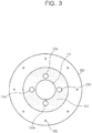
- FIG. 3 is a rear view of an ultra-high frequency partial discharge array sensor apparatus for a high-voltage power apparatus according to an exemplary embodiment of the present invention.
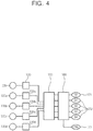
- FIG. 4 is a circuit diagram of an ultra-high frequency partial discharge array sensor apparatus for a high-voltage power apparatus according to an exemplary embodiment of the present invention.
- an ultra-high frequency partial discharge array sensor apparatus for a high-voltage power apparatus includes a sensing unit 110 which detects an electromagnetic wave partial discharge signal generated due to an internal defect of a high-voltage power apparatus and includes a plurality of sensors for detecting information related to the position where the defect occurs, an anti-surge filter unit 140 for which prevents a surge input from the sensing unit 110, a signal delay time adjusting unit 150 which equally adjusts delay times of signals input from the anti-surge filter unit 140, a signal switching unit 160 which selectively transmits or blocks signals input from the signal delay time adjusting unit 150, a connector unit 170 which connects signals transmitted through the signal switching unit 160 to the outside, and a sensor body 190 which has a receiving space therein.
- the sensing unit 110 includes a high sensitivity sensor 120 disposed at a center thereof and position estimation array sensors 120a to 120d which are disposed at regular intervals around the high sensitivity sensor 120.
- the anti-surge filter unit 140 includes a high sensitivity anti-surge filter 130 connected to the high sensitivity sensor 120 and array anti-surge filters 130a to 130d connected to the array sensors 120a to 120d, respectively.
- the signal delay time adjusting unit 150 is configured with electric wires, signal lines, or signal lines of a circuit substrate.
- the signal delay time adjusting unit 150 adjusts the length of signal lines connected from the sensing unit 110 to the signal switching unit 160 to make the times taken for signals detected by the sensors of the sensing unit 110 to reach the connector unit 170 equal to each other or changes the material of the signal lines to change the transmission rate of the signal route.
- the length or the material of the signal lines is set to an optimum value through an experiment.
- the signal switching unit 160 is configured with a switching element such as a semiconductor switch or a mechanical latch relay switch.
- the signal switching unit 160 relays signals detected by the sensing unit 110 to the connector unit 170 or switches signals of the array sensors 120a to 120d around the high sensitivity sensor 120 to be output to a high sensitivity connector 171 of the connector unit 170 together with a central sensor signal, thus increasing the sensitivity.
- the semiconductor switch or the mechanical latch relay switch as the switching element may receive an electric signal from a signal switch connector 173 to be switched or be maintained in a switched state.
- the connector unit 170 may have a hermetically sealed structure in which the high sensitivity connector 171, an array sensor connector 172, and the signal switch connector 173 which receives a switching command from the signal switching unit 160 are installed outside the sensor body 190.
- the sensor body 190 may have a structure in which a dielectric material 191 for fixing sensors is filled, the connector unit 170 is installed on its outside, and a flange 193 having bolt holes 192 through which the sensor body 190 is attached to a housing 210 of the power apparatus is formed.
- the array sensor apparatus When the array sensor apparatus is installed to detect an electromagnetic wave partial discharge signal generated due to an internal defect of the high-voltage power apparatus 210 such as a gas insulated switchgear, a power transformer, a reactor, or a high voltage rotating machine, the signals detected by the sensing unit 110 of the array sensor apparatus, that is, the signals detected by the sensors 120 and 120a to 120d, are input to the delay time adjusting unit 150 through the anti-surge filter unit 140.
- the high-voltage power apparatus 210 such as a gas insulated switchgear, a power transformer, a reactor, or a high voltage rotating machine
- the delay time adjusting unit 150 delays the signals from the sensors 120 and 120a to 120d to have a constant transmission time, and an output of the delay time adjusting unit 150 is transmitted to the high sensitivity connector 171 and the array sensor connector 172 of the connector unit 170 which are disposed on a sensor housing through the signal switching unit 160.
- the signals of the sensors 120 and 120a to 120d disposed at regular intervals on the array sensor apparatus having the sensor body 190 are output, it is possible to eliminate the inconvenience of using a plurality of sensors. Since the array sensors are attached to the sensor body 190 at regular intervals, it is possible to reduce the errors occurring during the measurement of discharge positions by providing accurate sensor coordinates.
- the delay times of signals detected by the respective sensors of the sensing unit 110 are adjusted and output by the signal delay time adjusting unit 150 installed in the sensor body 190, the signals detected by the respective sensors and measured by the connector unit 170 installed on the sensor housing have the same delay time. Further, it is possible to check the delay times and the states of the sensors when a signal is applied the input of the high sensitivity sensing unit 120 at the center through connector 171 thereof and detected by the respective sensors.
- Outputs which have been connected to the respective connectors of the connector unit 170 may be connected to an output of the high sensitivity sensing unit 120 through the switching operation of the signal switching unit 160 installed in the sensor body 190 such that the relative detection area of the sensor increases, thus increasing the sensitivity.
- a sensor which is not in use may be grounded to adjust the sensitivity and detection band by changing state of the signal switching unit 160.
- the array sensor apparatus of the present invention When the array sensor apparatus of the present invention is installed in the high-voltage power apparatus such as a transformer or a reactor to detect a partial discharge signal, the array sensor apparatus may be used to detect a partial discharge signal generated in the power apparatus using a position estimation method such as TDOA by detecting the signals from the four independent array sensors 120a to 120d which are disposed at regular intervals.
- a position estimation method such as TDOA
- the high sensitivity sensing unit 120 which can accurately measure the amplitude of a discharge signal and the array sensors 120a to 120d for precise position estimation are installed in one sensor body 190, one array sensor apparatus can be installed in the power apparatus and used for partial discharge measurement and position estimation. Therefore, it is possible to eliminate the inconvenience of using a plurality of array sensors and reduce the installing cost and effort.
- the array sensor apparatus of the present invention may be applied to partial discharge defect diagnosis of a high-voltage power apparatus having a three-dimensional structure such as a transformer and may be used for defect diagnosis and discharge position estimation of a reactor or a power structure as well as an oil-immersed transformer.
- the ultra-high frequency partial discharge array sensor apparatus for detecting an electromagnetic wave partial discharge signal generated due to an internal defect of a high-voltage power apparatus such as a gas insulated switchgear, a power transformer, a reactor, or a high voltage rotating machine according to the present invention has the following effects. Since the high sensitivity sensor for precisely measuring the amplitude of a discharge signal and the plurality of array sensors disposed at regular intervals are integrated as one body, it is possible to measure the position of an internal defect while detecting a discharge signal.
- the ultra-high frequency partial discharge array sensor apparatus for a high-voltage power apparatus of the invention can eliminate the inconvenience of using a plurality of sensors which are to be installed on a housing of the high-voltage power apparatus to measure a discharge position while detecting a partial discharge generated due to the internal defect and increase the accuracy of measuring the position of the internal defect by providing accurate coordinates of individual sensors.
Landscapes
- Physics & Mathematics (AREA)
- General Physics & Mathematics (AREA)
- Testing Relating To Insulation (AREA)
- Gas-Insulated Switchgears (AREA)
Claims (8)
- Appareil capteur matriciel à décharge partielle à ultra haute fréquence pour un appareil de puissance à haute tension, comprenant:une unité de détection (110)qui détecte un signal de décharge partielle d'onde électromagnétique généré en raison d'un défaut interne d'un appareil de puissance à haute tension et comprend une pluralité de capteurs (120a, 120b, 120c, 120d) installés pour détecter des informations relatives à la position où le défaut se produit;une unité de filtre anti-surtension (140) qui empêche une entrée de surtension provenant de l'unité de détection;une unité de réglage de temps de retard de signal (150) qui règle également les temps de retard des signaux entrés depuis l'unité de filtre anti-surtension;une unité de commutation de signal (160) qui transmet ou bloque de manière sélective des signaux entrés depuis l'unité de réglage de temps de retard du signal;une unité connecteur (170) qui connecte un signal transmis depuis l'unité de commutation de signal vers l'extérieur; etun corps de capteur (190) qui possède un espace de réception.
- Appareil capteur matriciel à décharge partielle à ultra haute fréquence selon la revendication 1, dans lequel l'unité de détection comprend un capteur à haute sensibilité disposé au centre de celle-ci et une pluralité de capteurs matriciels pour l'estimation de position, disposés à intervalles réguliers autour du capteur à haute sensibilité.
- Appareil capteur matriciel à décharge partielle à ultra haute fréquence selon la revendication 2, dans lequel l'unité de filtre anti-surtension comprend: un filtre anti-surtension à haute sensibilité connecté au capteur à haute sensibilité et une pluralité de filtres anti-surtension connectés aux capteurs matriciels, respectivement.
- Appareil capteur matriciel à décharge partielle à ultra haute fréquence selon la revendication 1, dans lequel l'unité de réglage de temps de retard de signal est configurée avec des fils électriques, des lignes de signaux ou des lignes de signaux d'un substrat de circuit et ajuste la longueur des lignes de signaux connectées par l'unité de détection à l'unité de commutation de signal pour faire en sorte que les temps nécessaires aux signaux détectés par les capteurs respectifs de l'unité de détection pour accéder à l'unité de connecteur, soient égaux les uns aux autres.
- Appareil capteur matriciel à décharge partielle à ultra haute fréquence selon la revendication 1, dans lequel l'unité de réglage de temps de retard de signal est configurée avec des fils électriques, des lignes de signal, ou des lignes de signal d'un substrat de circuit et modifie le matériau des lignes de signal pour changer la vitesse de transmission du signal.
- Appareil capteur matriciel à décharge partielle à ultra haute fréquence selon la revendication 1, dans lequel l'unité de commutation de signal est configurée avec un commutateur à semi-conducteur ou un relais à bascule mécanique et des signaux de relais détectés par l'unité de détection à l'unité connecteur ou aux signaux de commutation des capteurs matriciels autour du capteur de haute sensibilité à la sortie vers un connecteur à haute sensibilité de l'unité connecteur avec un signal de capteur central, augmentant ainsi la sensibilité.
- Appareil capteur matriciel à décharge partielle à ultra haute fréquence selon la revendication 1, dans lequel l'unité connecteur présente une structure hermétiquement scellée dans laquelle un connecteur à haute sensibilité, un connecteur de capteur matriciel et un connecteur de commutation de signaux qui reçoit une commande de commutation provenant de l'unité de commutation de signaux, sont installés à l'extérieur du corps du capteur.
- Appareil capteur matriciel à décharge partielle à ultra haute fréquence selon la revendication 1, dans lequel le corps de capteur présente une structure dans laquelle est versé un matériau diélectrique pour fixer les capteurs, l'unité connecteur est installée à l'extérieur de celle-ci et une bride possédant des trous est constituée, trous à travers lesquels le corps de capteur est fixé à un boîtier de l'appareil de puissance.
Applications Claiming Priority (1)
| Application Number | Priority Date | Filing Date | Title |
|---|---|---|---|
| KR1020080113592A KR101022556B1 (ko) | 2008-11-14 | 2008-11-14 | 고전압 전력기기용 극초단파 부분방전 어레이 센서 장치 |
Publications (3)
| Publication Number | Publication Date |
|---|---|
| EP2187226A2 EP2187226A2 (fr) | 2010-05-19 |
| EP2187226A3 EP2187226A3 (fr) | 2017-05-10 |
| EP2187226B1 true EP2187226B1 (fr) | 2018-07-18 |
Family
ID=41728391
Family Applications (1)
| Application Number | Title | Priority Date | Filing Date |
|---|---|---|---|
| EP09171456.8A Active EP2187226B1 (fr) | 2008-11-14 | 2009-09-28 | Appareil capteur matriciel à ultra-haute fréquence de décharge partielle pour appareil électrique haute tension |
Country Status (3)
| Country | Link |
|---|---|
| US (1) | US8294471B2 (fr) |
| EP (1) | EP2187226B1 (fr) |
| KR (1) | KR101022556B1 (fr) |
Families Citing this family (26)
| Publication number | Priority date | Publication date | Assignee | Title |
|---|---|---|---|---|
| ES2379831A1 (es) * | 2010-05-26 | 2012-05-04 | Universidad Politécnica de Madrid | PROCEDIMIENTO DE MONITORIZACIÓN CONTINUA Y DIAGNÓSTICO DE FUENTES DE DESCARGAS PARCIALES (DPs) EN CABLES DE ALTA TENSIÓN DURANTE SU CONEXIÓN Y FUNCIONAMIENTO EN LA RED, Y SISTEMA FÍSICO PARA LA PUESTA EN PRÁCTICA DEL PROCEDIMIENTO. |
| CN101949996A (zh) * | 2010-07-29 | 2011-01-19 | 大连世有电力科技有限公司 | 用于检测变压器局部放电信号的超声传感器 |
| KR101103667B1 (ko) * | 2010-11-15 | 2012-01-11 | 한국전기연구원 | 센서 부착 기구 |
| CN102129019A (zh) * | 2011-03-04 | 2011-07-20 | 上海华乘电气科技有限公司 | 一种用于开关设备绝缘检测的传感器 |
| US9329221B2 (en) * | 2011-04-06 | 2016-05-03 | Mitsubishi Electric Corporation | Partial discharge sensor |
| CN102323523B (zh) * | 2011-06-02 | 2014-01-29 | 平高集团有限公司 | 一种测量gis局部放电用的内置耦合器 |
| CN102645620B (zh) * | 2012-05-17 | 2015-02-11 | 广东电网公司电力科学研究院 | 基于时频特征参数的变电站多源局部放电检测方法及装置 |
| KR101181713B1 (ko) | 2012-05-24 | 2012-09-10 | 대영종합산기(주) | 변전?배전용 하이브리드 pd검측기 및 이를 통한 변전?배전설비 pd진단방법 |
| KR101352520B1 (ko) * | 2012-11-01 | 2014-01-17 | 엘에스산전 주식회사 | 전력설비용 극초단파 부분 방전 센서 반 조립체 및 전력설비용 극초단파 부분 방전 센서 조립체 |
| CN103076546B (zh) * | 2013-01-11 | 2014-10-08 | 国家电网公司 | 气体绝缘组合电器中电磁波传播特性试验装置及试验方法 |
| CN103558517A (zh) * | 2013-10-29 | 2014-02-05 | 云南电网公司楚雄供电局 | 基于能量变化定位高压设备放电源的方法 |
| FR3015043B1 (fr) * | 2013-12-12 | 2016-01-29 | Alstom Technology Ltd | Capteur uhf de decharges partielles integre dans les elements de raccordement d'un poste electrique haute tension isole au gaz |
| CN103698678B (zh) * | 2013-12-13 | 2016-08-31 | 上海交通大学 | 一种多路局部放电信号并行连接方法及装置 |
| CN103884967B (zh) * | 2014-02-13 | 2016-05-04 | 国家电网公司 | 一种适用于特高压换流变压器绕组内部局部放电定位方法及装置 |
| CN103913680B (zh) * | 2014-03-17 | 2016-09-07 | 上海交通大学 | 基于时延误差随机模拟与统计分析的局部放电定位方法 |
| CN106841937A (zh) * | 2016-12-19 | 2017-06-13 | 国网山东省电力公司泰安供电公司 | 一种电声联合的变压器局部放电带电检测方法及系统 |
| CN107085171B (zh) * | 2017-04-01 | 2019-10-11 | 西安交通大学 | 一种用于变电站局部放电测向的特高频相控阵的优化布置方法 |
| KR101942376B1 (ko) * | 2017-04-20 | 2019-04-17 | 현대일렉트릭앤에너지시스템(주) | 절연물의 결함 검출장치 |
| CA3007729A1 (fr) | 2017-06-12 | 2018-12-12 | Vibrosystm Inc. | Methode de surveillance de decharges partielles dans une machine electrique a haute tension, et cable de connexion associe |
| CN108181557B (zh) * | 2017-12-29 | 2020-05-05 | 上海交通大学 | 一种确定特高频局部放电信号方位的方法 |
| CN108548997B (zh) * | 2018-04-16 | 2020-11-06 | 上海交通大学 | 一种变电站空间局部放电定位方法及系统 |
| CN108717154B (zh) * | 2018-04-20 | 2020-05-19 | 国家电网公司 | 开关柜放电在线监测仪 |
| CN112014693B (zh) * | 2020-08-18 | 2023-01-31 | 江苏方天电力技术有限公司 | 基于波速不确定性的电缆局部放电定位方法及系统 |
| CA3223487A1 (fr) * | 2021-06-29 | 2023-01-05 | Maebh LARKIN | Dispositif et procede de surveillance multiparametriques et non invasifs d'anomalie de decharge en arc |
| CN114859148B (zh) * | 2022-01-19 | 2025-11-21 | 西安交通大学 | 电抗器绝缘故障光学推扫定位方法 |
| CN115372742A (zh) * | 2022-08-24 | 2022-11-22 | 广东电网有限责任公司 | 空心电抗器故障检测器、方法、装置及设备 |
Family Cites Families (15)
| Publication number | Priority date | Publication date | Assignee | Title |
|---|---|---|---|---|
| GB566591A (en) * | 1943-06-17 | 1945-01-04 | Kapella Ltd | Improvements in or relating to apparatus for measuring the degree of roughness of a surface |
| JPH0750144B2 (ja) * | 1987-09-17 | 1995-05-31 | 中部電力株式会社 | 部分放電位置標定方法 |
| JPH0750147B2 (ja) * | 1989-06-14 | 1995-05-31 | 株式会社日立製作所 | ガス絶縁電気機器の異常位置標定方法および装置 |
| JPH04372881A (ja) * | 1991-06-21 | 1992-12-25 | Toshiba Corp | 予測保全装置 |
| JPH05304719A (ja) * | 1992-04-24 | 1993-11-16 | Mitsubishi Electric Corp | ガス絶縁機器の部分放電位置標定装置 |
| JP3357691B2 (ja) * | 1992-09-22 | 2002-12-16 | 株式会社東芝 | 部分放電検出装置 |
| US5506511A (en) * | 1994-09-09 | 1996-04-09 | Electric Power Research Institute Inc. | Method of electrically detecting on-site partial discharges in the insulating medium of an electrical power transformer and apparatus therefor |
| WO1998053334A1 (fr) * | 1997-05-21 | 1998-11-26 | Hitachi, Ltd. | Detecteur de decharge partielle pour appareil isole au gaz |
| JPH10170591A (ja) * | 1996-12-05 | 1998-06-26 | Toshiba Corp | 外層接地機器の部分放電検出装置及び部分放電検出方法 |
| JP2003084027A (ja) | 2001-09-12 | 2003-03-19 | Mitsubishi Electric Corp | 部分放電発生位置標定装置および標定方法 |
| KR200278981Y1 (ko) * | 2002-03-29 | 2002-06-20 | (주) 피에스디테크 | 방사 전자파를 이용한 전력기기의 부분방전 검출장치 |
| US7030621B2 (en) * | 2004-05-04 | 2006-04-18 | General Electric Company | Low current AC partial discharge diagnostic system for wiring diagnostics |
| WO2006019164A1 (fr) * | 2004-08-20 | 2006-02-23 | Kabushiki Kaisha Toshiba | Dispositif et procede pour detecter la decharge partielle d’une machine electrique rotative |
| KR100774098B1 (ko) * | 2006-04-17 | 2007-11-06 | 엘에스산전 주식회사 | 가스절연 개폐장치 |
| KR20080113592A (ko) | 2007-06-25 | 2008-12-31 | 김동현 | 미끄러짐 방지 도로 포장체의 시공 방법 |
-
2008
- 2008-11-14 KR KR1020080113592A patent/KR101022556B1/ko active Active
-
2009
- 2009-09-25 US US12/567,042 patent/US8294471B2/en active Active
- 2009-09-28 EP EP09171456.8A patent/EP2187226B1/fr active Active
Non-Patent Citations (1)
| Title |
|---|
| None * |
Also Published As
| Publication number | Publication date |
|---|---|
| US20100123464A1 (en) | 2010-05-20 |
| EP2187226A2 (fr) | 2010-05-19 |
| KR101022556B1 (ko) | 2011-03-16 |
| KR20100054610A (ko) | 2010-05-25 |
| EP2187226A3 (fr) | 2017-05-10 |
| US8294471B2 (en) | 2012-10-23 |
Similar Documents
| Publication | Publication Date | Title |
|---|---|---|
| EP2187226B1 (fr) | Appareil capteur matriciel à ultra-haute fréquence de décharge partielle pour appareil électrique haute tension | |
| US11435242B2 (en) | Increasing sensitivity of a sensor using an encoded signal | |
| US9482697B2 (en) | Combined measuring and detection system | |
| EP3779476B1 (fr) | Circuit de mesure de capacité, et dispositif de mesure de déplacement de capacité | |
| JP5165058B2 (ja) | 電力器機の部分放電位置検出システム及び放電位置検出方法 | |
| US20020130587A1 (en) | Method and device for non-contact detection of external electric or magnetic fields | |
| US20140253092A1 (en) | Method and apparatus of diagnosing plasma in plasma space | |
| WO2003048791A3 (fr) | Analyseur de circuit haute frequence | |
| EP2618117B1 (fr) | Dispositif de détection permettant de détecter le niveau d'un matériau, niveau de liquide et température | |
| WO2008089341A3 (fr) | Système de détection de défauts dans des circuits électroniques haute fréquence | |
| JP6498709B2 (ja) | 検知装置及び物質検知方法 | |
| KR102681682B1 (ko) | 센서 집적 회로들 | |
| JP4872989B2 (ja) | 静電容量型センサ部品、物体搭載体、半導体製造装置および液晶表示素子製造装置 | |
| KR102829760B1 (ko) | Prpd 분석용 절연진단 센서를 내장한 스마트 붓싱의 설계 및 제조 기술 | |
| RU220371U1 (ru) | Беспроводной датчик измерения температуры | |
| KR20010053918A (ko) | 알에프 파워계측장치 | |
| JP2745959B2 (ja) | 密閉形開閉装置の主回路異常区間検出装置 | |
| JP2025153433A (ja) | 超音波風速計、及び風速測定方法 | |
| WO2025233151A1 (fr) | Mesure de puissance non intrusive pour câbles d'alimentation multiconducteurs | |
| JP2697480B2 (ja) | 密閉形開閉装置の主回路異常検出装置 | |
| JPH06105439A (ja) | 部分放電検出装置 | |
| JP2000187055A (ja) | ガス絶縁機器における部分放電検出装置 | |
| SE428503B (sv) | Forfarande for att vid metning av ett materials egenskaper medelst ett mikrovagsfrekvent metningsforfarande kompensera inverkan pa metningsresultatet av tillfelliga variationer i antennernas och materialets inbordes leg | |
| JPH09211098A (ja) | 電波探知装置 | |
| KR20040079050A (ko) | 전력케이블에서의 부분방전 발생위치 측정시스템 |
Legal Events
| Date | Code | Title | Description |
|---|---|---|---|
| PUAI | Public reference made under article 153(3) epc to a published international application that has entered the european phase |
Free format text: ORIGINAL CODE: 0009012 |
|
| AK | Designated contracting states |
Kind code of ref document: A2 Designated state(s): AT BE BG CH CY CZ DE DK EE ES FI FR GB GR HR HU IE IS IT LI LT LU LV MC MK MT NL NO PL PT RO SE SI SK SM TR |
|
| AX | Request for extension of the european patent |
Extension state: AL BA RS |
|
| PUAL | Search report despatched |
Free format text: ORIGINAL CODE: 0009013 |
|
| AK | Designated contracting states |
Kind code of ref document: A3 Designated state(s): AT BE BG CH CY CZ DE DK EE ES FI FR GB GR HR HU IE IS IT LI LT LU LV MC MK MT NL NO PL PT RO SE SI SK SM TR |
|
| AX | Request for extension of the european patent |
Extension state: AL BA RS |
|
| RIC1 | Information provided on ipc code assigned before grant |
Ipc: G01R 31/12 20060101AFI20170406BHEP Ipc: G01R 29/08 20060101ALN20170406BHEP |
|
| 17P | Request for examination filed |
Effective date: 20171109 |
|
| RBV | Designated contracting states (corrected) |
Designated state(s): AT BE BG CH CY CZ DE DK EE ES FI FR GB GR HR HU IE IS IT LI LT LU LV MC MK MT NL NO PL PT RO SE SI SK SM TR |
|
| GRAP | Despatch of communication of intention to grant a patent |
Free format text: ORIGINAL CODE: EPIDOSNIGR1 |
|
| RIC1 | Information provided on ipc code assigned before grant |
Ipc: G01R 29/08 20060101ALN20180109BHEP Ipc: G01R 31/12 20060101AFI20180109BHEP |
|
| INTG | Intention to grant announced |
Effective date: 20180209 |
|
| GRAS | Grant fee paid |
Free format text: ORIGINAL CODE: EPIDOSNIGR3 |
|
| GRAA | (expected) grant |
Free format text: ORIGINAL CODE: 0009210 |
|
| AK | Designated contracting states |
Kind code of ref document: B1 Designated state(s): AT BE BG CH CY CZ DE DK EE ES FI FR GB GR HR HU IE IS IT LI LT LU LV MC MK MT NL NO PL PT RO SE SI SK SM TR |
|
| REG | Reference to a national code |
Ref country code: GB Ref legal event code: FG4D |
|
| REG | Reference to a national code |
Ref country code: CH Ref legal event code: EP |
|
| REG | Reference to a national code |
Ref country code: IE Ref legal event code: FG4D |
|
| REG | Reference to a national code |
Ref country code: AT Ref legal event code: REF Ref document number: 1019942 Country of ref document: AT Kind code of ref document: T Effective date: 20180815 |
|
| REG | Reference to a national code |
Ref country code: DE Ref legal event code: R096 Ref document number: 602009053289 Country of ref document: DE |
|
| REG | Reference to a national code |
Ref country code: NL Ref legal event code: MP Effective date: 20180718 |
|
| REG | Reference to a national code |
Ref country code: LT Ref legal event code: MG4D |
|
| REG | Reference to a national code |
Ref country code: AT Ref legal event code: MK05 Ref document number: 1019942 Country of ref document: AT Kind code of ref document: T Effective date: 20180718 |
|
| PG25 | Lapsed in a contracting state [announced via postgrant information from national office to epo] |
Ref country code: NL Free format text: LAPSE BECAUSE OF FAILURE TO SUBMIT A TRANSLATION OF THE DESCRIPTION OR TO PAY THE FEE WITHIN THE PRESCRIBED TIME-LIMIT Effective date: 20180718 |
|
| PG25 | Lapsed in a contracting state [announced via postgrant information from national office to epo] |
Ref country code: FI Free format text: LAPSE BECAUSE OF FAILURE TO SUBMIT A TRANSLATION OF THE DESCRIPTION OR TO PAY THE FEE WITHIN THE PRESCRIBED TIME-LIMIT Effective date: 20180718 Ref country code: GR Free format text: LAPSE BECAUSE OF FAILURE TO SUBMIT A TRANSLATION OF THE DESCRIPTION OR TO PAY THE FEE WITHIN THE PRESCRIBED TIME-LIMIT Effective date: 20181019 Ref country code: NO Free format text: LAPSE BECAUSE OF FAILURE TO SUBMIT A TRANSLATION OF THE DESCRIPTION OR TO PAY THE FEE WITHIN THE PRESCRIBED TIME-LIMIT Effective date: 20181018 Ref country code: SE Free format text: LAPSE BECAUSE OF FAILURE TO SUBMIT A TRANSLATION OF THE DESCRIPTION OR TO PAY THE FEE WITHIN THE PRESCRIBED TIME-LIMIT Effective date: 20180718 Ref country code: IS Free format text: LAPSE BECAUSE OF FAILURE TO SUBMIT A TRANSLATION OF THE DESCRIPTION OR TO PAY THE FEE WITHIN THE PRESCRIBED TIME-LIMIT Effective date: 20181118 Ref country code: AT Free format text: LAPSE BECAUSE OF FAILURE TO SUBMIT A TRANSLATION OF THE DESCRIPTION OR TO PAY THE FEE WITHIN THE PRESCRIBED TIME-LIMIT Effective date: 20180718 Ref country code: PL Free format text: LAPSE BECAUSE OF FAILURE TO SUBMIT A TRANSLATION OF THE DESCRIPTION OR TO PAY THE FEE WITHIN THE PRESCRIBED TIME-LIMIT Effective date: 20180718 Ref country code: LT Free format text: LAPSE BECAUSE OF FAILURE TO SUBMIT A TRANSLATION OF THE DESCRIPTION OR TO PAY THE FEE WITHIN THE PRESCRIBED TIME-LIMIT Effective date: 20180718 Ref country code: BG Free format text: LAPSE BECAUSE OF FAILURE TO SUBMIT A TRANSLATION OF THE DESCRIPTION OR TO PAY THE FEE WITHIN THE PRESCRIBED TIME-LIMIT Effective date: 20181018 |
|
| PG25 | Lapsed in a contracting state [announced via postgrant information from national office to epo] |
Ref country code: HR Free format text: LAPSE BECAUSE OF FAILURE TO SUBMIT A TRANSLATION OF THE DESCRIPTION OR TO PAY THE FEE WITHIN THE PRESCRIBED TIME-LIMIT Effective date: 20180718 Ref country code: LV Free format text: LAPSE BECAUSE OF FAILURE TO SUBMIT A TRANSLATION OF THE DESCRIPTION OR TO PAY THE FEE WITHIN THE PRESCRIBED TIME-LIMIT Effective date: 20180718 Ref country code: ES Free format text: LAPSE BECAUSE OF FAILURE TO SUBMIT A TRANSLATION OF THE DESCRIPTION OR TO PAY THE FEE WITHIN THE PRESCRIBED TIME-LIMIT Effective date: 20180718 |
|
| REG | Reference to a national code |
Ref country code: DE Ref legal event code: R097 Ref document number: 602009053289 Country of ref document: DE |
|
| PG25 | Lapsed in a contracting state [announced via postgrant information from national office to epo] |
Ref country code: MC Free format text: LAPSE BECAUSE OF FAILURE TO SUBMIT A TRANSLATION OF THE DESCRIPTION OR TO PAY THE FEE WITHIN THE PRESCRIBED TIME-LIMIT Effective date: 20180718 Ref country code: CZ Free format text: LAPSE BECAUSE OF FAILURE TO SUBMIT A TRANSLATION OF THE DESCRIPTION OR TO PAY THE FEE WITHIN THE PRESCRIBED TIME-LIMIT Effective date: 20180718 Ref country code: RO Free format text: LAPSE BECAUSE OF FAILURE TO SUBMIT A TRANSLATION OF THE DESCRIPTION OR TO PAY THE FEE WITHIN THE PRESCRIBED TIME-LIMIT Effective date: 20180718 Ref country code: EE Free format text: LAPSE BECAUSE OF FAILURE TO SUBMIT A TRANSLATION OF THE DESCRIPTION OR TO PAY THE FEE WITHIN THE PRESCRIBED TIME-LIMIT Effective date: 20180718 Ref country code: IT Free format text: LAPSE BECAUSE OF FAILURE TO SUBMIT A TRANSLATION OF THE DESCRIPTION OR TO PAY THE FEE WITHIN THE PRESCRIBED TIME-LIMIT Effective date: 20180718 |
|
| REG | Reference to a national code |
Ref country code: CH Ref legal event code: PL |
|
| PLBE | No opposition filed within time limit |
Free format text: ORIGINAL CODE: 0009261 |
|
| STAA | Information on the status of an ep patent application or granted ep patent |
Free format text: STATUS: NO OPPOSITION FILED WITHIN TIME LIMIT |
|
| PG25 | Lapsed in a contracting state [announced via postgrant information from national office to epo] |
Ref country code: DK Free format text: LAPSE BECAUSE OF FAILURE TO SUBMIT A TRANSLATION OF THE DESCRIPTION OR TO PAY THE FEE WITHIN THE PRESCRIBED TIME-LIMIT Effective date: 20180718 Ref country code: SM Free format text: LAPSE BECAUSE OF FAILURE TO SUBMIT A TRANSLATION OF THE DESCRIPTION OR TO PAY THE FEE WITHIN THE PRESCRIBED TIME-LIMIT Effective date: 20180718 Ref country code: SK Free format text: LAPSE BECAUSE OF FAILURE TO SUBMIT A TRANSLATION OF THE DESCRIPTION OR TO PAY THE FEE WITHIN THE PRESCRIBED TIME-LIMIT Effective date: 20180718 |
|
| REG | Reference to a national code |
Ref country code: BE Ref legal event code: MM Effective date: 20180930 |
|
| 26N | No opposition filed |
Effective date: 20190423 |
|
| GBPC | Gb: european patent ceased through non-payment of renewal fee |
Effective date: 20181018 |
|
| REG | Reference to a national code |
Ref country code: IE Ref legal event code: MM4A |
|
| PG25 | Lapsed in a contracting state [announced via postgrant information from national office to epo] |
Ref country code: LU Free format text: LAPSE BECAUSE OF NON-PAYMENT OF DUE FEES Effective date: 20180928 |
|
| PG25 | Lapsed in a contracting state [announced via postgrant information from national office to epo] |
Ref country code: IE Free format text: LAPSE BECAUSE OF NON-PAYMENT OF DUE FEES Effective date: 20180928 |
|
| PG25 | Lapsed in a contracting state [announced via postgrant information from national office to epo] |
Ref country code: SI Free format text: LAPSE BECAUSE OF FAILURE TO SUBMIT A TRANSLATION OF THE DESCRIPTION OR TO PAY THE FEE WITHIN THE PRESCRIBED TIME-LIMIT Effective date: 20180718 Ref country code: FR Free format text: LAPSE BECAUSE OF NON-PAYMENT OF DUE FEES Effective date: 20180930 Ref country code: LI Free format text: LAPSE BECAUSE OF NON-PAYMENT OF DUE FEES Effective date: 20180930 Ref country code: CH Free format text: LAPSE BECAUSE OF NON-PAYMENT OF DUE FEES Effective date: 20180930 Ref country code: BE Free format text: LAPSE BECAUSE OF NON-PAYMENT OF DUE FEES Effective date: 20180930 |
|
| PG25 | Lapsed in a contracting state [announced via postgrant information from national office to epo] |
Ref country code: GB Free format text: LAPSE BECAUSE OF NON-PAYMENT OF DUE FEES Effective date: 20181018 |
|
| PG25 | Lapsed in a contracting state [announced via postgrant information from national office to epo] |
Ref country code: MT Free format text: LAPSE BECAUSE OF NON-PAYMENT OF DUE FEES Effective date: 20180928 |
|
| PG25 | Lapsed in a contracting state [announced via postgrant information from national office to epo] |
Ref country code: TR Free format text: LAPSE BECAUSE OF FAILURE TO SUBMIT A TRANSLATION OF THE DESCRIPTION OR TO PAY THE FEE WITHIN THE PRESCRIBED TIME-LIMIT Effective date: 20180718 |
|
| PG25 | Lapsed in a contracting state [announced via postgrant information from national office to epo] |
Ref country code: PT Free format text: LAPSE BECAUSE OF FAILURE TO SUBMIT A TRANSLATION OF THE DESCRIPTION OR TO PAY THE FEE WITHIN THE PRESCRIBED TIME-LIMIT Effective date: 20180718 Ref country code: HU Free format text: LAPSE BECAUSE OF FAILURE TO SUBMIT A TRANSLATION OF THE DESCRIPTION OR TO PAY THE FEE WITHIN THE PRESCRIBED TIME-LIMIT; INVALID AB INITIO Effective date: 20090928 |
|
| PG25 | Lapsed in a contracting state [announced via postgrant information from national office to epo] |
Ref country code: MK Free format text: LAPSE BECAUSE OF NON-PAYMENT OF DUE FEES Effective date: 20180718 Ref country code: CY Free format text: LAPSE BECAUSE OF FAILURE TO SUBMIT A TRANSLATION OF THE DESCRIPTION OR TO PAY THE FEE WITHIN THE PRESCRIBED TIME-LIMIT Effective date: 20180718 |
|
| PGFP | Annual fee paid to national office [announced via postgrant information from national office to epo] |
Ref country code: DE Payment date: 20250923 Year of fee payment: 17 |