EP2187380A1 - Afficheur d'image et procédé d'affichage d'image - Google Patents
Afficheur d'image et procédé d'affichage d'image Download PDFInfo
- Publication number
- EP2187380A1 EP2187380A1 EP08765607A EP08765607A EP2187380A1 EP 2187380 A1 EP2187380 A1 EP 2187380A1 EP 08765607 A EP08765607 A EP 08765607A EP 08765607 A EP08765607 A EP 08765607A EP 2187380 A1 EP2187380 A1 EP 2187380A1
- Authority
- EP
- European Patent Office
- Prior art keywords
- image
- image signal
- image display
- pixels
- period
- Prior art date
- Legal status (The legal status is an assumption and is not a legal conclusion. Google has not performed a legal analysis and makes no representation as to the accuracy of the status listed.)
- Ceased
Links
Images










Classifications
-
- G—PHYSICS
- G09—EDUCATION; CRYPTOGRAPHY; DISPLAY; ADVERTISING; SEALS
- G09G—ARRANGEMENTS OR CIRCUITS FOR CONTROL OF INDICATING DEVICES USING STATIC MEANS TO PRESENT VARIABLE INFORMATION
- G09G3/00—Control arrangements or circuits, of interest only in connection with visual indicators other than cathode-ray tubes
- G09G3/20—Control arrangements or circuits, of interest only in connection with visual indicators other than cathode-ray tubes for presentation of an assembly of a number of characters, e.g. a page, by composing the assembly by combination of individual elements arranged in a matrix no fixed position being assigned to or needed to be assigned to the individual characters or partial characters
-
- H—ELECTRICITY
- H04—ELECTRIC COMMUNICATION TECHNIQUE
- H04N—PICTORIAL COMMUNICATION, e.g. TELEVISION
- H04N5/00—Details of television systems
- H04N5/14—Picture signal circuitry for video frequency region
- H04N5/20—Circuitry for controlling amplitude response
- H04N5/202—Gamma control
-
- G—PHYSICS
- G09—EDUCATION; CRYPTOGRAPHY; DISPLAY; ADVERTISING; SEALS
- G09G—ARRANGEMENTS OR CIRCUITS FOR CONTROL OF INDICATING DEVICES USING STATIC MEANS TO PRESENT VARIABLE INFORMATION
- G09G2320/00—Control of display operating conditions
- G09G2320/02—Improving the quality of display appearance
- G09G2320/0261—Improving the quality of display appearance in the context of movement of objects on the screen or movement of the observer relative to the screen
-
- G—PHYSICS
- G09—EDUCATION; CRYPTOGRAPHY; DISPLAY; ADVERTISING; SEALS
- G09G—ARRANGEMENTS OR CIRCUITS FOR CONTROL OF INDICATING DEVICES USING STATIC MEANS TO PRESENT VARIABLE INFORMATION
- G09G2320/00—Control of display operating conditions
- G09G2320/02—Improving the quality of display appearance
- G09G2320/0271—Adjustment of the gradation levels within the range of the gradation scale, e.g. by redistribution or clipping
-
- G—PHYSICS
- G09—EDUCATION; CRYPTOGRAPHY; DISPLAY; ADVERTISING; SEALS
- G09G—ARRANGEMENTS OR CIRCUITS FOR CONTROL OF INDICATING DEVICES USING STATIC MEANS TO PRESENT VARIABLE INFORMATION
- G09G2320/00—Control of display operating conditions
- G09G2320/10—Special adaptations of display systems for operation with variable images
- G09G2320/103—Detection of image changes, e.g. determination of an index representative of the image change
-
- G—PHYSICS
- G09—EDUCATION; CRYPTOGRAPHY; DISPLAY; ADVERTISING; SEALS
- G09G—ARRANGEMENTS OR CIRCUITS FOR CONTROL OF INDICATING DEVICES USING STATIC MEANS TO PRESENT VARIABLE INFORMATION
- G09G2340/00—Aspects of display data processing
- G09G2340/04—Changes in size, position or resolution of an image
- G09G2340/0407—Resolution change, inclusive of the use of different resolutions for different screen areas
- G09G2340/0435—Change or adaptation of the frame rate of the video stream
-
- G—PHYSICS
- G09—EDUCATION; CRYPTOGRAPHY; DISPLAY; ADVERTISING; SEALS
- G09G—ARRANGEMENTS OR CIRCUITS FOR CONTROL OF INDICATING DEVICES USING STATIC MEANS TO PRESENT VARIABLE INFORMATION
- G09G2340/00—Aspects of display data processing
- G09G2340/16—Determination of a pixel data signal depending on the signal applied in the previous frame
-
- G—PHYSICS
- G09—EDUCATION; CRYPTOGRAPHY; DISPLAY; ADVERTISING; SEALS
- G09G—ARRANGEMENTS OR CIRCUITS FOR CONTROL OF INDICATING DEVICES USING STATIC MEANS TO PRESENT VARIABLE INFORMATION
- G09G2360/00—Aspects of the architecture of display systems
- G09G2360/18—Use of a frame buffer in a display terminal, inclusive of the display panel
-
- G—PHYSICS
- G09—EDUCATION; CRYPTOGRAPHY; DISPLAY; ADVERTISING; SEALS
- G09G—ARRANGEMENTS OR CIRCUITS FOR CONTROL OF INDICATING DEVICES USING STATIC MEANS TO PRESENT VARIABLE INFORMATION
- G09G3/00—Control arrangements or circuits, of interest only in connection with visual indicators other than cathode-ray tubes
- G09G3/20—Control arrangements or circuits, of interest only in connection with visual indicators other than cathode-ray tubes for presentation of an assembly of a number of characters, e.g. a page, by composing the assembly by combination of individual elements arranged in a matrix no fixed position being assigned to or needed to be assigned to the individual characters or partial characters
- G09G3/2007—Display of intermediate tones
- G09G3/2018—Display of intermediate tones by time modulation using two or more time intervals
- G09G3/2022—Display of intermediate tones by time modulation using two or more time intervals using sub-frames
- G09G3/2025—Display of intermediate tones by time modulation using two or more time intervals using sub-frames the sub-frames having all the same time duration
-
- G—PHYSICS
- G09—EDUCATION; CRYPTOGRAPHY; DISPLAY; ADVERTISING; SEALS
- G09G—ARRANGEMENTS OR CIRCUITS FOR CONTROL OF INDICATING DEVICES USING STATIC MEANS TO PRESENT VARIABLE INFORMATION
- G09G3/00—Control arrangements or circuits, of interest only in connection with visual indicators other than cathode-ray tubes
- G09G3/20—Control arrangements or circuits, of interest only in connection with visual indicators other than cathode-ray tubes for presentation of an assembly of a number of characters, e.g. a page, by composing the assembly by combination of individual elements arranged in a matrix no fixed position being assigned to or needed to be assigned to the individual characters or partial characters
- G09G3/34—Control arrangements or circuits, of interest only in connection with visual indicators other than cathode-ray tubes for presentation of an assembly of a number of characters, e.g. a page, by composing the assembly by combination of individual elements arranged in a matrix no fixed position being assigned to or needed to be assigned to the individual characters or partial characters by control of light from an independent source
- G09G3/36—Control arrangements or circuits, of interest only in connection with visual indicators other than cathode-ray tubes for presentation of an assembly of a number of characters, e.g. a page, by composing the assembly by combination of individual elements arranged in a matrix no fixed position being assigned to or needed to be assigned to the individual characters or partial characters by control of light from an independent source using liquid crystals
- G09G3/3611—Control of matrices with row and column drivers
Definitions
- the present invention relates to an image display device such as a liquid crystal display device or the like and to an image display method.
- An image display device using a hold type display device e.g., a liquid crystal display device, has such a problem that quality of a moving image deteriorates (edge blurs).
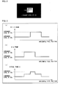
- the deterioration of quality (blurred edge) of a moving image which occurs in a conventional hold type display device will be explained by taking, as an example, a case where a region whose image signal luminance level is 75% moves horizontally on a background whose image signal luminance level is 25% as illustrated in Fig. 2 .
- Fig. 16 illustrates a distribution of input image signal luminance levels respectively corresponding to the pixels in a single horizontal line of a single screen corresponding to image signals inputted to a certain frame at the time of the aforementioned image display.
- Fig. 17 illustrates temporal transition of the display luminance distribution in the conventional hold type display device. This temporal transition is observed when such an image moves horizontally.
- an observer viewing an image watches a horizontally moving object, so that the observer recognizes, as a luminance level which can be felt by eyes, an integration quantity obtained by integrating display luminance levels in directions indicated by arrows.
- a luminance response time of the display device is ignored, and numeric values respectively indicate states of luminance levels of the pixels in the single horizontal line of the single frame in case where the single frame period is divided into eight periods.
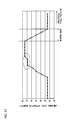
- Fig. 19 is a graph indicative of the distribution of the luminance levels.
- This luminance level distribution is such that there are lines each indicative of a region whose luminance level is 25% and there is a line indicative of a region whose luminance level is 75% and these lines are connected by line segments each of which is inclined in the vicinity of a border between the regions. A horizontal width of this inclined line segment is recognized as the blurred edge. This causes the deterioration of quality of a moving image in the hold type display device.
- the most simple method for reducing the blurred edge is such that a minimum luminance level (black) display period is provided in a part of a display single frame.
- a minimum luminance level (black) display period is provided in a part of a display single frame.
- bright and dark states are repeated in the entire screen at each cycle of a single frame, which results in occurrence of flickers.
- a minimum luminance level display period is necessarily provided in a single frame period, which results in drop of the luminance level.
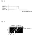
- Fig. 20 illustrates a distribution of input image signal luminance levels corresponding to pixels on a single horizontal line of a single screen corresponding to image signals inputted to a certain frame at the time of the image display illustrated in Fig. 8 .
- Fig. 21 illustrates temporal transition of a display luminance distribution in a conventional hold type display device. This temporal transition is observed when such an image moves horizontally.
- Fig. 22 is a table showing numeric values respectively indicating states of luminance levels of the pixels in a single horizontal line of a single frame period in case where the single frame period is divided into eight periods.
- an integration quantity of the luminance levels is an average of the luminance levels in the time periods added up in the arrow directions, and is the distribution felt by the observer's eyes is the integration quantity .
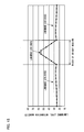
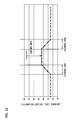
- Fig. 23 is a graph indicative of the distribution of the luminance levels.
- the background has a high luminance level and a moving region has a low luminance level, so that the luminance of the moving region appears to be higher. This phenomenon causes the deterioration of quality of a moving image.
- Patent Literature 1 proposes a method for reducing the blurred edge without generating any flickers. This method is such that: as illustrated in Fig. 24 , a virtual frame image corresponding to a temporal midpoint between two consecutive frames is estimated and generated, and the thus generated virtual frame image is inserted between the two consecutive frames so as to reduce the blurred edge, thereby preventing the deterioration of quality of a moving image.
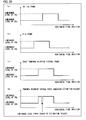
- a luminance level distribution of input image signals in an (N-1)th frame is as illustrated in Fig. 25(a)
- a luminance level distribution of input image signals in an N th frame is as illustrated in Fig. 25(b) .
- the luminance level distribution is such that the region whose luminance level is 75% is positioned at a midpoint between the (N-1)th frame and the N th frame as illustrated in Fig. 25(c) .
- the virtual frame corresponding to the temporal midpoint contains an error, this results in a state illustrated in Fig. 25(d) .
- a pixel at a position where a luminance level should be 75% has a luminance level of 25%.
- numeric values respectively indicating states of luminance levels in a single frame period are as illustrated in Fig. 26
- a distribution of luminance level integration quantities viewed by an observer watching a moving object is as illustrated in Fig. 27 .
- This example shows that: in the vicinity of a right edge of the region whose luminance level is 75%, estimation failure does not occur concerning the virtual frame, so that there is no problem in the distribution of the luminance level integration quantities, and a width of the blurred edge is improved due to the original effect compared with the case of the conventional hold type display device illustrated in Fig. 19 .
- level differences in a distribution waveform of the luminance level integration quantities.
- the level differences cause the deterioration of quality, e.g., an image noise, and the like.
- Patent Literature 2 discloses a technique in which an image free from a high spatial frequency and an image emphasizing the high spatial frequency are repeatedly displayed so as to prevent a moving image from blurring.
- frame images are generated from a single input image, so that there occurs deviation in a relationship between time space and luminance centroid with respect to an observer who watches an object moving on a screen, which raises such a problem that it is impossible to appropriately keep a distribution of integrated luminances which are observed at a front end and at a rear end of a displayed object.
- positive values of a high spatial frequency component are removed, which results in such a problem that a luminance of an emphasized frame is always high and flickers occur in the entire screen.
- Patent Literature 3 A technique disclosed by the following Patent Literature 3 can solve the problems in Patent Literature 2 and Patent Literature 3.
- Patent Literature 3 which regards an invention also invented by the present inventors, is such that: a single frame period is divided into a sub frame period A and a sub frame period B, and a blurring process is carried out in the sub frame period A, and an emphasizing process is carried out in the sub frame period B, so as to improve quality of a moving image, thereby solving the problem in Patent Literature 1.
- Patent Literature 3 discloses a technique in which: a blurred frame image is generated, and an average value between the latest frame and a previous frame is used.
- Patent Literature 3 it is possible to realize an appropriate relationship between space time and luminance centroid with respect to the observer who watches an object moving on the screen, so that it is possible to keep an appropriate distribution of integrated luminances observed at a front edge and at a rear edge of a displayed object.
- a broad luminance of the blurred frame and a broad luminance of the emphasizing frame are identical to each other, so that no flickers occur in the entire screen.
- Patent Literature 3 has the following problem.
- An object of the present invention is to provide an image display device and an image display method each of which is capable of providing adequate quality of a moving image regardless of an image signal level of an input image signal.
- An image display device displays an image in accordance with image signals of respective pixels in each frame period wherein a frame period corresponds to image signals for a single screen, said image display device comprising: a dividing section for dividing a single frame period into a plurality of periods including at least one sub frame A period and at least one sub frame B period; a converting section for converting image signal levels of input image signals for the respective pixels so that the converted image signal levels are within a range from a predetermined lower limit to a predetermined upper limit; a first image processing section for carrying out a smoothing process with respect to the converted image signals of the respective pixels in the sub frame A period; a second image processing section for carrying out an emphasizing process with respect to the converted image signals of the respective pixels in the sub frame B period; and an image display section for displaying an image in accordance with (i) the image signals which have been subjected to the smoothing process by the first image processing section and which correspond to the respective pixels and (ii) the image signals which have been subject
- a single frame period is divided into a plurality of periods including at least one sub frame A period and at least one sub frame B period, and there are provided: a first image processing section for carrying out a smoothing process with respect to image signals of the respective pixels in the sub frame A period; and a second image processing section for carrying out an emphasizing process with respect to image signals of the respective pixels in the sub frame B period.
- the present invention comprises a converting section for converting image signal levels of input image signals for the respective pixels so that the converted image signal levels are within a range from a predetermined lower limit to a predetermined upper limit.
- image signal levels of the input image signals can be converted so that the converted image signal levels are within a predetermined certain range. Therefore, the emphasizing process can be carried out regardless of the image signal levels of the inputted image signals, so that it is possible to carry out an appropriate emphasizing process.
- it is possible to improve quality of a moving image it is possible to obtain a high-quality moving image
- the image signal levels of the inputted image signal it is possible to improve quality of a moving image (it is possible to obtain a high-quality moving image) regardless of the image signal level of the inputted image signal.
- image signals of an (N-1)th frame and the N th frame are used to generate a virtual sub frame Q in which an image signal level of each pixel corresponds to an image signal level obtained by averaging image signal levels for respective pixels of both the frames.
- a single frame period is time-divided into two sub frames both of which are equal to each other in terms of a time period.
- an image signal obtained by averaging (weighted averaging or simple averaging) image signals of pixels in a peripheral certain range (reference range) including a target pixel of the virtual sub frame Q is outputted as a sub frame A image signal.
- the averaging process smoothing process
- the emphasizing process is carried out in the sub frame B period.
- Fig. 1 is a diagram schematically illustrating an image display device of the present embodiment.
- the image display device is configured so that a controller LSI1 is connected to an image display section 12 of a liquid crystal panel or the like, a previous frame memory 32, and a display frame memory 33.
- the controller LSI1 includes: an image signal preconverting section (converting section) 2; a timing controller (dividing section) 40; a previous frame memory controller 41; a display frame memory controller 42; a time average image signal level generating section (virtual sub frame generating section) 63; a motion degree calculating section (detecting section) 3; a sub frame A multi line memory 44; a sub frame B multi line memory 45; a sub frame A image signal generating section (first image processing section) 46; a sub frame B image signal generating section (second image processing section) 47; and a data selector 48.
- the converting section 2 is a characteristic feature of the present embodiment.
- the converting section 2 carries out a predetermined converting process with respect to an input image signal inputted from the outside and outputs the thus processed input image signal. More specifically, the converting section 2 carries out the conversion so that an input image signal is within a range between a predetermined upper limit and a predetermined lower limit. This conversion can be carried out in accordance with user's preference or design intention of a product developer. A specific manner in which the converting process is carried out and an effect of improving quality of a moving image will be described later.
- the timing controller 40 generates timings of a sub frame A period and sub frame B period which are obtained by time-dividing an input frame period of 60Hz. Further, the timing controller 40 controls the previous frame memory controller 41, a display frame memory controller 42, and a data selector 48.
- the time average image signal level generating section 63 causes a calculating circuit or software to calculate an average value between a previous frame image signal level for a target pixel and a display frame (current frame) image signal level for the target pixel, and generates a virtual sub frame Q in which this average value corresponds to an image signal level.
- the detecting section 3 uses a numeric value to indicate a motion degree (degree of motion) of a video by comparing the previous frame image signal with the current frame image signal, and restricts a difference between the below-described sub frame A image signal or the sub frame B image signal and a preconverted image signal for the target pixel in accordance with the numeric value (calculation result).
- the motion degree is regarded as the number of pixels each of which is such that an image signal difference between the previous frame and the current frame in view of the same position is not less than a predetermined value in a range (reference range) defined by a horizontal X pixel and a vertical Y line with the target pixel centered in the range.
- a range reference range
- differences each of which is a difference between an image signal level in the previous frame and an image signal level in the current frame are accumulated while more greatly weighting an image signal level of a reference pixel positioned closer to the target pixel in horizontal and vertical directions, and the thus obtained value is regarded as the motion degree.
- a pixel movement amount (motion vector amount) is estimated, and the thus estimated amount is regarded as the motion degree.
- An example of a method for estimating the pixel movement amount is as follows. Image signals of a certain region in a current frame which region centers a target pixel centered therein and image signals of plural certain regions in a previous frame are successively compared. In the previous frame, if a central pixel of the certain region is such that a total of level differences from the image signals of the certain region of the current frame is small, this central pixel is regarded as having moved to the target pixel of the current frame, and an amount of this movement is regarded as a movement amount of the target pixel.
- the movement amount of the target pixel (i.e., an absolute value of the motion vector) is regarded as the motion degree without any modification, or a total of movement amounts of peripheral pixels centering the target pixel is regarded as the motion degree of the pixel, or a value obtained by accumulating the image signal levels is regarded as the motion degree of the pixel while more greatly weighting an image signal level of a reference pixel positioned closer to the target pixel.
- the method not only the movement amount of the pixel but also movement amounts of peripheral pixels are accumulated, so that it is possible to appropriately process a signal even if an abnormal vector is detected to some extent, but this method results in higher cost of the control section.
- Each of the sub frame A/B multi line memories 44 and 45 retains image signals, corresponding to the Y line, in and around the horizontal line being scanned for carrying out display.
- the first image processing section 46 inputs, via the sub frame A multi line memory 44, image signals corresponding to the range in the virtual sub frame Q which range is defined by the horizontal X pixel and the vertical Y line with the target pixel centered in the range. Thereafter, the first image processing section 46 accumulates image signal levels of respective pixels in the region, defined by the horizontal X pixel and the vertical Y line (i.e., the reference range) while weighting the image signal levels, and a total of the accumulated values is divided by a total of weighting factors for the respective pixels in the reference range, and the thus obtained value is regarded as a sub frame A image signal.
- the weighting may be carried out by equally weighting image signal levels of the respective pixels in the reference range (by using the weighting factor equal to each other) or may be carried out by more greatly weighting an image signal of a pixel positioned closer to the target pixel.
- the second image processing section 47 inputs, via the sub frame B multi line memory, image signals of the respective pixels in the reference range with the target pixel centered. Thereafter, with respect to the reference range, the second image processing section 47 carries out calculation in the same manner as in generation of the sub frame A image signal.
- the second image processing section 47 generates the sub frame B image signal for the target pixel so that a time integration quantity of a display luminance level in a single virtual frame period, which display luminance level is constituted of (i) an image signal obtained as a result of the calculation and (ii) the sub frame B image signal, is identical to a luminance level observed in case where an image based on a preconverted image signal for the target pixel becomes still.
- the sub frame B image signal becomes an image signal subjected to an emphasizing process.
- the sub frame B image signal is determined so that a time integration quantity of a luminance level of each pixel in a single frame period is identical to a luminance level observed in case where an image based on a preconverted image signal for the target pixel becomes still.
- a data selector 48 selects the sub frame A image signal or the sub frame B image signal in accordance with a current display sub frame phase so as to forward the selected signal to the image display section 12.
- a single horizontal line of a screen in case where an object whose width is larger than a movement amount in a single frame period and whose luminance level is 75% moves horizontally on a background whose luminance level is 25% as illustrated in Fig. 2 .
- a luminance level distribution of input image signals of an (N-1)th frame is as illustrated in (a) of Fig. 3
- a luminance level distribution of input image signals of an N th frame is as illustrated in (b) of Fig. 3 .
- a luminance level distribution in a single horizontal line of the virtual sub frame Q using, as an image signal level, an intermediate value of input image signal levels for each pixel after conversion of the N th frame and the (N-1)th frame is as illustrated in (c) of Fig. 3 .
- the respective pixels of the reference range are equally weighted, and the image signal levels are accumulated with the weighting factors equal to each other, and a total of the accumulated values is divided by a total of the weighting factors for the respective pixels in the range.
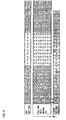
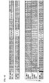
- a luminance level of the virtual sub frame Q image signal, a luminance level of the preconverted image signal, a luminance level of the sub frame A period, a luminance level of the sub frame B period, and an eye movement tracking luminance integration quantity are indicated as numeric values in Fig. 4 .
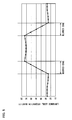
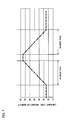
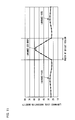
- a distribution of luminance levels (tracking integration quantities) seen by an observer watching a moving object is as illustrated in Fig. 5 .
- Fig. 6 is a diagram corresponding to Fig. 4 using a conventional image display device.
- Fig. 7 is a drawing corresponding to Fig. 5 using a conventional image display device.
- (a) of Fig. 8 indicates a luminance level distribution of input image signals of the (N-1)th frame
- (b) of Fig. 9 indicates a luminance level distribution of input image signals of the N th frame
- (c) of Fig. 9 indicates a luminance level distribution in a single horizontal line of the virtual sub frame Q constituted of an image signal level obtained by averaging input image signals of the N th frame and the (N-1)th frame for each pixel.
- image signal levels of the respective pixels in the reference range are equally weighted, and the image signal levels are accumulated with the weighting factors equal to each other, and a total of the accumulated values is divided by a total of the weighting factors for the respective pixels so as to obtain a value.
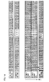
- the luminance level of the virtual sub frame Q image signal, the luminance level of the preconverted image signal, the luminance level of the sub frame A period, the luminance level of the sub frame B period, and a numerical value indicative of the eye movement tracking luminance integration quantity are illustrated in Fig. 10 .
- Fig. 11 a distribution of luminance levels (tracking integration quantities) which are seen by an observer watching a moving object is as illustrated in Fig. 11 .
- Fig. 12 is a diagram corresponding to Fig. 10 using a conventional image display device.
- Fig. 13 is a diagram corresponding to Fig. 11 using a conventional image display device. According to Fig. 11 , compared with Fig. 13 , the luminance level less drops and a bright area less expands. While, the luminance of a portion whose luminance level should be 25% rises.
- the respective pixels in the reference range are equally weighted in generating the sub frame A image signal and the sub frame B image signal.
- the luminance of a portion whose luminance level should be 25% rises
- this Example 3 it is possible to suppress the rise of the luminance by weighting the image signal levels of the respective pixels in the reference range.
- the image signal levels are accumulated by more greatly weighting an image signal level of a pixel positioned closer to the target pixel, and a total of the accumulated values is divided by a total of the weighting factors for the respective pixels so as to obtain a value
- this Experimental Example is under the same condition as Experimental Example 2 except that the thus obtained value is used.
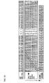
- the luminance level of the virtual sub frame Q image signal, the luminance level of the preconverted image signal, a luminance level of the sub frame A period, the luminance level of the sub frame B period, and a numeric value indicative of the eye movement tracking luminance integration quantity are illustrated in Fig. 14 .
- a distribution of luminance levels (tracking integration quantities) which are seen by an observer watching a moving object is as illustrated in Fig. 15 .
- Example 2 compared with the conventional example of Fig. 13 , the luminance level less drops and the bright region less expands. Further, in case of simple average, compared with the example of Fig. 11 illustrating (Experimental Example 2), rise of the luminance level is suppressed at 25%, i.e., the original luminance level. That is, according to the present Example, it is possible to improve the blurred edge, to reduce drop of the luminance level, and to reduce an error with respect to a luminance level which should be displayed.
- a lowest luminance level of the preconverted image signal is 25%, and a highest luminance level of the preconverted image signal is 75%.
- a lowest luminance level of the sub frame B period of Fig. 4 is 2%, and a highest luminance level of the sub frame B period of Fig. 4 is 98%.
- a lowest luminance level of the preconverted image signal is 25%, and a highest luminance level of the preconverted image signal is 75%.
- a lowest luminance level of the sub frame B period of Fig. 6 is 15%, and a highest luminance level of the sub frame B period of Fig. 6 is 100%.
- a lowest luminance level of the preconverted image signal is 25%, and a highest luminance level of the preconverted image signal is 75%.
- a lowest luminance level of the sub frame B period of Fig. 14 is 11%, and a highest luminance level of the sub frame B period of Fig. 14 is 100%.
- an ideal luminance level in the sub frame B may be less than 0% or exceed 100%.
- display cannot be carried out with a luminance level less than 0% or exceeding 100%. In this case, there occurs such a problem that the effect of improving quality of a moving image may be lower than the effect illustrated in Fig. 15 .
- a converting section 2 is provided, and an input image signal is preconverted.
- a range of the input image signal is converted into 25% to 75% for example.
- an input image signal whose luminance level (image signal level) ranging from 0% to 100% is preconverted into a luminance level ranging from 25% to 75%, so that it is possible to carry out a sufficient emphasizing process even in case where an input image signal of 0% or 100% is inputted. As a result, it is possible to avoid deterioration of the effect of improving quality of a moving image.
- the luminance level of the input image signal is converted, for example, in accordance with the following equation.
- Lc Lmax ⁇ 0.25 + Li ⁇ 0.5
- Li represents a luminance level
- Lc represents a luminance level after conversion
- Lmax represents a maximum luminance level of the input image signal.
- the maximum luminance level Lmax of the input image signal is 100%, so that the luminance level Lc after conversion is 25%.
- the luminance level Li of the input image signal can range from 0% to 100%, so that the luminance level Lc after conversion ranges from 25% to 75%.
- an image signal level of an image signal in a target pixel of a previous frame is identical to an image signal level of an image signal of a display frame.
- a display luminance of the single virtual frame period is ideally identical to a display luminance of an actual single frame period constituted of the sub frame A and the sub frame B.
- the display luminance of the still image is ideally identical to a display luminance corresponding to an image signal of a current frame.
- the aforementioned display method in accordance with how a motion degree (degree of motion) of a video changes.
- a motion degree degree of motion
- the aforementioned display method is switched in accordance with a single threshold value, a border line caused by the switching occurs, so that the border line may be seen by an observer.
- a preferable mode is as follows. If the motion degree is so great that a minute luminance difference is not recognized by an observer, the aforementioned display method is carried out. If the motion degree is so small that a minute luminance difference is recognized by an observer, the aforementioned display method is stopped. Further, in case where the motion degree for carrying out the aforementioned display method is set as a first threshold value and the motion degree for stopping the aforementioned display method is set as a second threshold value, when a motion degree is between the first threshold value and the second threshold value, the sub frame A image signal and the sub frame B image signal used in the aforementioned display method may be changed in accordance with a change of the motion degree.
- a range which can be indicated by the sub frame A image signal and the sub frame B image signal in response to the preconverted input image signal is limited by a signal level difference, a signal level ratio, and the like.
- the image signal preconverting section 2 will be described. If a display luminance level is too high in response to a minimum luminance level, a black display appears to be gray, so that the contrast performance deteriorates. Further, if a display luminance is too low in response to the maximum luminance level, a display maximum luminance performance deteriorates.
- the converted image signal is adjusted at the design stage in accordance with an expected video, a display environment, and the like, or it is preferable that a user switches the converted image signal.
- the image signal conversion method includes: a method in which a calculation circuit or a calculation program carries out calculation for conversion; a method in which a signal level converted in response to each signal level of an input image signal is kept in a conversion table in advance; and a similar method.
- Examples of a method for a user to change a conversion mode include: a method in which a parameter of a calculation circuit or a calculation program is made variable; and a method in which a plurality of conversion tables are made switchable.
- nonlinear signal conversion circuit results in higher cost, so that it may be so arranged that linear proportional conversion is carried out as conversion of the intermediate image signal.
- the gamma luminance property of the image display section 12 (e.g., a liquid crystal panel module) is adjusted so that an appropriate gamma luminance property is reproduced between the lower limit rated value and the upper limit rated value of the image signal, thereby carrying out an image display whose gamma luminance property is appropriate.
- an image signal level corresponding to a minimum luminance which can be displayed by the image display section 12 is set as the lower limit rated value.
- an image signal level corresponding to a maximum luminance which can be displayed by the image display section 12 is set as the upper limit rated value.
- the reference range centering the target pixel therein may partially deviate from an image display range. In this case, an appropriate signal process cannot be carried out.
- a border line may be generated in a video by switching the aforementioned display method.
- a distance D1 which is such a shortest distance that the reference range is within the screen
- a distance D2 which is longer than the distance D1.
- the distance D1 may be such a distance that the reference range slightly deviates from the screen.
- the aforementioned process (b) is carried out. Due to the distance D2, the aforementioned display method realizes effect of improving quality of a moving image in a large part of the screen. Further, due to the distance D2, it is possible to keep a range realized by the process (b) for preventing the observer from recognizing the border line caused by the switching.
- the distance d from the pixel to the end of the screen is detected by the sub frame A image signal generating section 46 and the sub frame B image signal generating section 47.
- a display method similar to the conventional method is gradually switched to the aforementioned display method for improving blurred motion as d becomes greater, so that a display image signal level does not drastically change even in case where a displayed object moving on the screen moves beyond a border line at which the display method changes, so that a strange feeling of the video is hardly recognized.
- D1 and D2 are respectively defined as Dy1 and Dy2
- D1 and D2 are respectively defined as Dx1 and Dx2.
- Dx1 and Dx2 are respectively defined as Dx1 and Dx2.
- Dy1 is 5% or less with respect to a vertical image length and Dx1 is 5% or less with respect to a horizontal image length
- Dy2 is 10% or less with respect to the vertical image length and Dx2 is be 10% or less with respect to the horizontal image length.
- the sub frame A image signal is calculated in accordance with an image signal of the virtual frame Q, but the configuration is not limited to this, and it may be so configured that the virtual frame Q is not generated and the sub frame A image signal is calculated in accordance with the input image signal calculated by the image signal preconverting section 2.
- an image is slightly impaired due to deviation of a relationship between time space and luminance centroid with respect to an observer watching an object moving on the screen, but quality of an image is expected to be improved to some extent.
- a single frame period is divided into the two sub frame periods, i.e., the sub frame A and the sub frame B period, but the configuration is not necessarily limited to this, and it may be so configured that the single frame period is divided into three sub frame periods.
- the image display device of the present invention can be configured as a liquid crystal television receiver for example. That is, it may be so configured that: there is provided a receiving section 14 which selects a channel as a tuner section, and receives television broadcast, and inputs a video signal indicative of a video transferred by the television broadcast to a controller LSI1 as an input image signal.
- the controller LSI1 includes a frame memory 13 which can read and write the input image signal.
- the image display section 12 includes a liquid crystal panel and can be configured so as to display an image based on an output image signal transmitted from the controller LSI1.
- an image display device of the present invention displays an image in accordance with image signals of respective pixels in each frame period wherein a frame period corresponds to image signals for a single screen
- said image display device comprising: a dividing section for dividing a single frame period into a plurality of periods including at least one sub frame A period and at least one sub frame B period; a converting section for converting image signal levels of input image signals for the respective pixels so that the converted image signal levels are within a range from a predetermined lower limit to a predetermined upper limit; a first image processing section for carrying out a smoothing process with respect to the converted image signals of the respective pixels in the sub frame A period; a second image processing section for carrying out an emphasizing process with respect to the converted image signals of the respective pixels in the sub frame B period; and an image display section for displaying an image in accordance with (i) the image signals which have been subjected to the smoothing process by the first image processing section and which correspond to
- an image display method of the present invention an image is displayed in accordance with image signals of respective pixels in each frame period wherein a frame period corresponds to image signals for a single screen, said image display method comprising: dividing a single frame period into a plurality of periods including at least one sub frame A period and at least one sub frame B period; converting image signal levels of input image signals for the respective pixels so that the converted image signal levels are within a range from a predetermined lower limit to a predetermined upper limit; and carrying out a smoothing process with respect to the converted image signals of the respective pixels in the sub frame A period and for carrying out an emphasizing process with respect to the converted image signals of the respective pixels in the sub frame B period.
- a single frame period is divided into a plurality of periods including at least one sub frame A period and at least one sub frame B period, and there are provided: a first image processing section for carrying out a smoothing process with respect to image signals of the respective pixels in the sub frame A period; and a second image processing section for carrying out an emphasizing process with respect to image signals of the respective pixels in the sub frame B period.
- the present invention comprises a converting section for converting image signal levels of input image signals for the respective pixels so that the converted image signal levels are within a range from a predetermined lower limit to a predetermined upper limit.
- image signal levels of the input image signals can be converted so that the converted image signal levels are within a predetermined certain range. Therefore, the emphasizing process can be carried out regardless of the image signal levels of the inputted image signals, so that it is possible to carry out an appropriate emphasizing process.
- it is possible to improve quality of a moving image it is possible to obtain a high-quality moving image
- the image signal levels of the inputted image signal it is possible to improve quality of a moving image (it is possible to obtain a high-quality moving image) regardless of the image signal level of the inputted image signal.
- the first image processing section calculates an average value of the converted input image signal levels of pixels included in a reference range having a target pixel so that the smoothing process uses the average value as each image signal level of the pixels in the reference range.
- the smoothing process calculates an average value of the converted input image signal levels of pixels included in a reference range having a target pixel so that the smoothing process uses the average value as each image signal level of the pixels in the reference range.
- the first image processing section calculates an average value of the converted input image signal levels of pixels included in a reference range having a target pixel so that the average value corresponds to an image signal level of the target pixel. That is, the converted input image signals are used to carry out the smoothing process. Thus, it is possible to carry out the smoothing process in a simple manner.
- the image display device of the present invention so as to further comprise a virtual sub frame generating section for generating a virtual sub frame whose signal level corresponds to an intermediate value of the converted input image signal levels for target pixels of consecutive two input frames, wherein the first image processing section calculates an average value of the converted input image signal levels of pixels included in a reference range having a target pixel in the virtual sub frame so that the smoothing process uses the average value as each image signal level of the pixels in the reference range.
- the image display method of the present invention so as to further comprises: generating a virtual sub frame whose signal level corresponds to an intermediate value of the converted input image signal levels for target pixels of consecutive two input frames, and wherein the smoothing process calculates an average value of the converted input image signal levels of pixels included in a reference range having a target pixel in the virtual sub frame so that the smoothing process uses the average value as each image signal level of the pixels in the reference range.
- the sub frame A period is constituted in accordance with the virtual sub frame, so that it is possible to avoid impairment of a quality of an image which impairment is caused by deviation of a relationship between time space and luminance centroid with respect to an observer watching an object moving on the image.
- the second image processing section carries out the emphasizing process so that a time-based integration quantity of a luminance level of the image display section in a single frame period which luminance level changes due to changes of the image signal levels of the respective pixels within the single frame period is identical to a time-based integration quantity of the luminance level of the image display section which luminance level is observed in case where the image becomes still at the converted image signal levels, said single frame period including the sub frame A period and the sub frame B period.
- the emphasizing process is carried out so that a time-based integration quantity of a luminance level of the image display section in a single frame period which luminance level changes due to changes of the image signal levels of the respective pixels within the single frame period is identical to a time-based integration quantity of the luminance level of the image display section which luminance level is observed in case where the image becomes still at the converted image signal levels, said single frame period including the sub frame A period and the sub frame B period.
- the second image processing section carries out the process so that a time integration quantity of a luminance level of the image display section in a single frame period which luminance level changes due to changes of the image signal levels of the respective pixels in the single frame period is identical to a time integration quantity of the luminance level of the image display section which luminance level is observed in case where the image becomes still at the converted image signal levels, said single frame period including the sub frame A period and the sub frame B period.
- the first image processing section accumulates the converted image signal levels for the pixels included in the reference range while more greatly weighting an image signal level of a pixel positioned closer to the target pixel, and averages the accumulated values for the pixels included in the reference range.
- the image display method of the present invention so that: in the smoothing process, the converted image signal levels for the pixels included in the reference range are accumulated while more greatly weighting an image signal level of a pixel positioned closer to the target pixel, and the accumulated values for the pixels included in the reference range.
- the image display device of the present invention it is preferable to configure the image display device of the present invention so that: the converting section carries out linear proportional conversion with respect to the input image signals.
- the linear proportional conversion is carried out, so that it is not necessary to prepare a complicate circuit for conversion.
- the converting section carries out nonlinear conversion so that a display luminance property in the image display section shows an appropriate gamma property while the image signal levels are within the range from the lower limit to the upper limit.
- the converting section carries out nonlinear conversion so that a display luminance property in a range from the lower limit to the upper limit in the image display section shows an appropriate gamma property.
- the gamma property in an actually displayed image can be made appropriate.
- a difference between a luminance level of the image display section which luminance level corresponds to the upper limit and a maximum luminance level which can be displayed by the image display section is not more than 25% with respect to a difference between the maximum luminance level which can be displayed by the image display section and a minimum luminance level which can be displayed by the image display section.
- a difference between a luminance level of the image display section which luminance level corresponds to the upper limit and a maximum luminance level which can be displayed by the image display section is not more than 10% with respect to a difference between the maximum luminance level which can be displayed by the image display section and a minimum luminance level which can be displayed by the image display section.
- a luminance level of the image display section which luminance level corresponds to the lower limit is equal to a minimum luminance level which can be displayed by the image display section.
- a luminance level of the image display section which luminance level corresponds to the lower limit is made equal to a minimum luminance level which can be displayed by the image display section, so that it is possible to prevent the contrast performance from deteriorating without unnecessarily raising the minimum luminance level.
- a luminance level of the image display section which luminance level corresponds to the upper limit is equal to a maximum luminance level which can be displayed by the image display section.
- a luminance level of the image display section which luminance level corresponds to the upper limit is made equal to a maximum luminance level which can be displayed by the image display section, so that it is possible to prevent the display maximum luminance from dropping.
- a gamma property of the image display section is determined so that a display luminance property shows an appropriate gamma property while the image signal levels are within the range from the lower limit to the upper limit.
- the image display device of the present invention so as to further comprise a detecting section for calculating a motion degree of a video, wherein:
- a motion degree of a video is calculated, and in case where the motion degree is larger than a second threshold value and smaller than a first threshold value, the smoothing process and the emphasizing process are carried out so that, as the motion degree is smaller, the image signal levels of the respective pixels are respectively more approximate to image signal levels of the converted input image signals.
- inexact luminance display causes significant deterioration of quality of the image. While, in case of displaying an image which quickly moves, a slight luminance display error is not recognized.
- the image display device comprises a detecting section for calculating a motion degree of a video, wherein: in case where the motion degree is larger than a second threshold value and smaller than a first threshold value, the first image processing section carries out the smoothing process and the second image processing section carries out the emphasizing process so that, as the motion degree is smaller, the image signal levels of the respective pixels are respectively more approximate to image signal levels of the converted input image signals.
- the process is carried out so that, as the motion degree is smaller, the image signal levels of the respective pixels are respectively more approximate to image signal levels of the converted input image signals.
- a second threshold value and smaller than a first threshold value for example, in case of displaying an image which slowly moves or an image which is slightly still
- the image display device of the present invention so that: in case where the motion degree is smaller than the second threshold value, the image display device displays the image in accordance with the converted input image signals.
- the image display device displays the image in accordance with the converted input image signals.
- the detecting section for calculating a motion degree of a video and in case where the motion degree is smaller than the second threshold value, the converted input image signals are outputted without any modification. That is, in case where the motion degree is smaller than the second threshold value (for example, in case of displaying an image which is almost still or a still image), the converted input image signals are outputted without any modification.
- the second threshold value for example, in case of displaying an image which is almost still or a still image
- the detecting section determines, as the motion degree of these pixels, a total value of the number of pixels in which a difference between an image signal level of a converted input image signal in a previous frame and an image signal level of a converted input image signal in a current frame for that pixel is not less than a predetermined value.
- the motion degree of these pixels is a total value of the number of pixels in which a difference between an image signal level of a converted input image signal in a previous frame and an image signal level of a converted input image signal in a current frame for that pixel is not less than a predetermined value.
- the detecting section determines, as the motion degree of these pixels, a value obtained by accumulating differences between image signal levels of the converted input image signals in a previous frame and image signal levels of the converted input image signals in a current frame, in these pixels while more greatly weighting an image signal level of a pixel positioned closer to this target pixel.
- the motion degree of these pixels is a value obtained by accumulating differences between image signal levels of the converted input image signals in a previous frame and image signal levels of the converted input image signals in a current frame, in these pixels while more greatly weighting an image signal level of a pixel positioned closer to this target pixel.
- the detecting section determines, as the motion degree of these pixels, an absolute value of a motion vector calculated for this target pixel.
- the motion degree of these pixels is an absolute value of a motion vector calculated for this target pixel.
- the detecting section determines, as the motion degree of these pixels, a value obtained by accumulating absolute values of motion vectors each of which is calculated in each of these pixels, while more greatly weighting an image signal level of a pixel positioned closer to this target pixel.
- the motion degree of these pixels is a value obtained by accumulating absolute values of motion vectors each of which is calculated in each of these pixels, while more greatly weighting an image signal level of a pixel positioned closer to this target pixel.
- a distance between the target pixel and a closer end of the screen in a vertical direction and/or a horizontal direction is represented by d, and 0 ⁇ D1 ⁇ D2, and in case where D2 ⁇ d, the first image processing section carries out the smoothing process and the second image processing section carries out the emphasizing process, and in case where D1 ⁇ d ⁇ D2, the first image processing section and the second image processing section carry out image processing so that, as d is smaller, a difference between an output image signal and each of the converted input image signals is smaller, and in case where d ⁇ D1, the first image processing section and the second image processing section output the converted input image signals without any correction.
- a distance between the target pixel and a closer end of the screen in a vertical direction and/or a horizontal direction is represented by d, and O ⁇ D1 ⁇ D2, and in case where D2 ⁇ d, the emphasizing process is carried out which carrying out the smoothing process, and in case where D1 ⁇ d ⁇ D2, image processing is carried out so that a difference between an output image signal and each of the converted input image signals is smaller as d is smaller, and in case where d ⁇ D1, the converted input image signals are outputted without any correction.
- the reference range may partially deviate from the screen.
- the first image processing section carries out the smoothing process and the second image processing section carries out the emphasizing process
- D1 ⁇ d ⁇ D2 the first image processing section and the second image processing section carry out image processing so that, as d is smaller, a difference between an output image signal and each of the converted input image signals is smaller
- d ⁇ D1 the first image processing section and the second image processing section output the converted input image signals without any correction.
- the image display device of the present invention so that: in case where D1 and D2 in the vertical direction are respectively defined as Dy1 and Dy2 and in case where D 1 and D2 in the horizontal direction are respectively defined as Dx1 and Dx2, Dy1 ⁇ Dx1 and Dy2 ⁇ Dx2.
- Dy1 is not more than 5% with respect to a vertical image length and Dx1 is not more than 5% with respect to a horizontal image length.
- Dy2 is not more than 10% with respect to a vertical image length and Dx2 is not more than 10% with respect to a horizontal image length.
- the image display device and the image display method of the present invention are applicable to a liquid crystal or organic EL or an E-ink and the like, moving image display appliances each using a display device for carrying out hold mode display, a television, a personal computer monitor, a DVD player provided with a monitor, a game machine, a car navigation system, a mobile video player, a mobile phone, and the like.
Landscapes
- Engineering & Computer Science (AREA)
- Physics & Mathematics (AREA)
- Computer Hardware Design (AREA)
- General Physics & Mathematics (AREA)
- Theoretical Computer Science (AREA)
- Multimedia (AREA)
- Signal Processing (AREA)
- Control Of Indicators Other Than Cathode Ray Tubes (AREA)
- Liquid Crystal (AREA)
- Liquid Crystal Display Device Control (AREA)
- Picture Signal Circuits (AREA)
- Transforming Electric Information Into Light Information (AREA)
Applications Claiming Priority (2)
| Application Number | Priority Date | Filing Date | Title |
|---|---|---|---|
| JP2007240136 | 2007-09-14 | ||
| PCT/JP2008/060897 WO2009034757A1 (fr) | 2007-09-14 | 2008-06-13 | Afficheur d'image et procédé d'affichage d'image |
Publications (2)
| Publication Number | Publication Date |
|---|---|
| EP2187380A1 true EP2187380A1 (fr) | 2010-05-19 |
| EP2187380A4 EP2187380A4 (fr) | 2011-05-04 |
Family
ID=40451769
Family Applications (1)
| Application Number | Title | Priority Date | Filing Date |
|---|---|---|---|
| EP08765607A Ceased EP2187380A4 (fr) | 2007-09-14 | 2008-06-13 | Afficheur d'image et procédé d'affichage d'image |
Country Status (5)
| Country | Link |
|---|---|
| US (1) | US8482579B2 (fr) |
| EP (1) | EP2187380A4 (fr) |
| JP (1) | JP5221550B2 (fr) |
| CN (1) | CN101779231B (fr) |
| WO (1) | WO2009034757A1 (fr) |
Families Citing this family (24)
| Publication number | Priority date | Publication date | Assignee | Title |
|---|---|---|---|---|
| CN101273399B (zh) * | 2005-11-07 | 2012-10-31 | 夏普株式会社 | 图像显示方法和图像显示装置 |
| CN102124511B (zh) * | 2008-08-22 | 2013-06-12 | 夏普株式会社 | 图像信号处理装置、图像信号处理方法、图像显示装置、电视接收机、电子设备 |
| US20120162528A1 (en) * | 2010-01-13 | 2012-06-28 | Shinya Kiuchi | Video processing device and video display device |
| JP5811602B2 (ja) | 2010-12-16 | 2015-11-11 | ソニー株式会社 | 画像生成装置、プログラム、画像表示システム、および画像表示装置 |
| JP5535090B2 (ja) * | 2011-01-04 | 2014-07-02 | 三菱電機株式会社 | 表示装置および表示装置の画面データ作成装置 |
| US11052288B1 (en) | 2013-01-19 | 2021-07-06 | Bertec Corporation | Force measurement system |
| US10856796B1 (en) | 2013-01-19 | 2020-12-08 | Bertec Corporation | Force measurement system |
| US10413230B1 (en) | 2013-01-19 | 2019-09-17 | Bertec Corporation | Force measurement system |
| US10231662B1 (en) | 2013-01-19 | 2019-03-19 | Bertec Corporation | Force measurement system |
| US11540744B1 (en) | 2013-01-19 | 2023-01-03 | Bertec Corporation | Force measurement system |
| US12161477B1 (en) | 2013-01-19 | 2024-12-10 | Bertec Corporation | Force measurement system |
| US10646153B1 (en) | 2013-01-19 | 2020-05-12 | Bertec Corporation | Force measurement system |
| US9526443B1 (en) | 2013-01-19 | 2016-12-27 | Bertec Corporation | Force and/or motion measurement system and a method of testing a subject |
| US11857331B1 (en) | 2013-01-19 | 2024-01-02 | Bertec Corporation | Force measurement system |
| US9081436B1 (en) * | 2013-01-19 | 2015-07-14 | Bertec Corporation | Force and/or motion measurement system and a method of testing a subject using the same |
| US10010286B1 (en) | 2013-01-19 | 2018-07-03 | Bertec Corporation | Force measurement system |
| US9770203B1 (en) | 2013-01-19 | 2017-09-26 | Bertec Corporation | Force measurement system and a method of testing a subject |
| US11311209B1 (en) | 2013-01-19 | 2022-04-26 | Bertec Corporation | Force measurement system and a motion base used therein |
| CN104144345B (zh) * | 2013-09-18 | 2016-08-17 | 腾讯科技(深圳)有限公司 | 在移动终端进行实时图像识别的方法及该移动终端 |
| JP6317577B2 (ja) | 2013-12-04 | 2018-04-25 | キヤノン株式会社 | 映像信号処理装置及びその制御方法 |
| CN105741813B (zh) * | 2016-05-11 | 2018-01-12 | 京东方科技集团股份有限公司 | 用于图像处理的系统、方法及显示装置 |
| JP7147038B2 (ja) * | 2019-02-20 | 2022-10-04 | 富士フイルム株式会社 | 表示制御装置、撮像装置、表示制御方法、及び表示制御プログラム |
| CN110364113A (zh) * | 2019-06-24 | 2019-10-22 | 深圳市华星光电半导体显示技术有限公司 | 显示装置及其驱动方法 |
| WO2024161587A1 (fr) * | 2023-02-02 | 2024-08-08 | シャープディスプレイテクノロジー株式会社 | Dispositif d'affichage |
Family Cites Families (24)
| Publication number | Priority date | Publication date | Assignee | Title |
|---|---|---|---|---|
| JPH03295437A (ja) | 1990-04-13 | 1991-12-26 | Saginomiya Seisakusho Inc | 車両振動試験方法 |
| JP3295437B2 (ja) | 1991-03-29 | 2002-06-24 | 日本放送協会 | 表示装置 |
| KR100619377B1 (ko) * | 2000-02-22 | 2006-09-08 | 주식회사 팬택앤큐리텔 | 움직임 추정 방법 및 장치 |
| JP2002351382A (ja) | 2001-03-22 | 2002-12-06 | Victor Co Of Japan Ltd | ディスプレイ装置 |
| JP3660610B2 (ja) | 2001-07-10 | 2005-06-15 | 株式会社東芝 | 画像表示方法 |
| TW200303001A (en) * | 2001-11-09 | 2003-08-16 | Sharp Kk | Liquid crystal display device |
| JP2003207762A (ja) * | 2001-11-09 | 2003-07-25 | Sharp Corp | 液晶表示装置 |
| TW575864B (en) | 2001-11-09 | 2004-02-11 | Sharp Kk | Liquid crystal display device |
| JP3818649B2 (ja) | 2002-05-20 | 2006-09-06 | インターナショナル・ビジネス・マシーンズ・コーポレーション | 画像表示システム、画像表示方法、およびプログラム |
| US6782081B2 (en) | 2002-05-21 | 2004-08-24 | Bellsouth Intellectual Property Corporation | Automated delivery of instant message to a telephone line device |
| CN100412919C (zh) * | 2002-05-28 | 2008-08-20 | 皇家飞利浦电子股份有限公司 | 在变化的占空度中减少运动模糊 |
| JP2004318696A (ja) * | 2003-04-18 | 2004-11-11 | Konica Minolta Photo Imaging Inc | 画像処理方法、画像処理装置及び画像処理プログラム |
| JP4341839B2 (ja) * | 2003-11-17 | 2009-10-14 | シャープ株式会社 | 画像表示装置、電子機器、液晶テレビジョン装置、液晶モニタ装置、画像表示方法、表示制御プログラムおよび記録媒体 |
| CN101036387B (zh) * | 2004-06-30 | 2010-10-27 | 派尔高公司 | 检测mpeg视频流中的运动的方法和装置 |
| TW200623897A (en) | 2004-12-02 | 2006-07-01 | Seiko Epson Corp | Image display method, image display device, and projector |
| KR100696107B1 (ko) | 2005-04-11 | 2007-03-19 | 삼성전자주식회사 | 디스플레이장치 및 그 제어방법 |
| CN101273399B (zh) * | 2005-11-07 | 2012-10-31 | 夏普株式会社 | 图像显示方法和图像显示装置 |
| TWI324013B (en) * | 2006-02-22 | 2010-04-21 | Huper Lab Co Ltd | Video noise reduction method using adaptive spatial and motion-compensation temporal filters |
| JP4131281B2 (ja) | 2006-05-09 | 2008-08-13 | ソニー株式会社 | 画像表示装置、信号処理装置、および画像処理方法、並びにコンピュータ・プログラム |
| JP4172495B2 (ja) | 2006-05-09 | 2008-10-29 | ソニー株式会社 | 画像表示装置、信号処理装置、および画像処理方法、並びにコンピュータ・プログラム |
| US8054344B2 (en) * | 2006-06-16 | 2011-11-08 | Raytheon Company | Imaging system and method with intelligent digital zooming |
| JP5080899B2 (ja) | 2007-08-08 | 2012-11-21 | キヤノン株式会社 | 映像処理装置及びその制御方法 |
| JP2009053221A (ja) | 2007-08-23 | 2009-03-12 | Mitsubishi Electric Corp | 画像表示装置及び画像表示方法 |
| JP5049703B2 (ja) | 2007-08-28 | 2012-10-17 | 株式会社日立製作所 | 画像表示装置、画像処理回路およびその方法 |
-
2008
- 2008-06-13 JP JP2009532093A patent/JP5221550B2/ja not_active Expired - Fee Related
- 2008-06-13 US US12/452,511 patent/US8482579B2/en not_active Expired - Fee Related
- 2008-06-13 CN CN2008801021224A patent/CN101779231B/zh not_active Expired - Fee Related
- 2008-06-13 WO PCT/JP2008/060897 patent/WO2009034757A1/fr not_active Ceased
- 2008-06-13 EP EP08765607A patent/EP2187380A4/fr not_active Ceased
Also Published As
| Publication number | Publication date |
|---|---|
| CN101779231A (zh) | 2010-07-14 |
| US8482579B2 (en) | 2013-07-09 |
| WO2009034757A1 (fr) | 2009-03-19 |
| EP2187380A4 (fr) | 2011-05-04 |
| CN101779231B (zh) | 2012-09-12 |
| US20100118044A1 (en) | 2010-05-13 |
| JP5221550B2 (ja) | 2013-06-26 |
| JPWO2009034757A1 (ja) | 2010-12-24 |
Similar Documents
| Publication | Publication Date | Title |
|---|---|---|
| US8482579B2 (en) | Image display device and image display method | |
| US7929000B2 (en) | Image display device | |
| EP2323123B1 (fr) | Dispositif de traitement de signal d'image, procédé de traitement de signal d'image, dispositif d'affichage d'image, récepteur de télévision et dispositif électronique | |
| US20080030514A1 (en) | Display device | |
| US7903129B2 (en) | Image display device | |
| EP2184733B1 (fr) | Dispositif d'affichage d'image | |
| JP4231071B2 (ja) | 画像表示装置、画像表示方法および画像表示プログラム | |
| KR100643230B1 (ko) | 디스플레이장치의 제어방법 | |
| CN101529902A (zh) | 图像显示装置及方法、图像处理装置及方法 | |
| US20090122188A1 (en) | Image display device and method | |
| JP2008118505A (ja) | 画像表示装置及び方法、画像処理装置及び方法 | |
| JP2009109694A (ja) | 表示装置 | |
| WO2007149424A2 (fr) | procédé et système pour une insertion de trame dans un système d'affichage numérique | |
| JPWO2011155258A1 (ja) | 画像処理装置および方法、画像表示装置および方法 | |
| JP2008268286A (ja) | 画像表示装置 | |
| JP5005260B2 (ja) | 画像表示装置 | |
| KR20080041581A (ko) | 화상 처리 장치, 화상 처리 방법, 전기 광학 장치 및전자기기 | |
| KR101577703B1 (ko) | 흐림과 이중 윤곽의 효과를 줄이는 비디오 화상 디스플레이방법과 이러한 방법을 구현하는 디바이스 | |
| JP2010091711A (ja) | 表示装置 | |
| CN102577346A (zh) | 影像信号处理装置 | |
| JP2010191189A (ja) | 液晶表示装置、制御方法および電子機器 |
Legal Events
| Date | Code | Title | Description |
|---|---|---|---|
| PUAI | Public reference made under article 153(3) epc to a published international application that has entered the european phase |
Free format text: ORIGINAL CODE: 0009012 |
|
| 17P | Request for examination filed |
Effective date: 20100114 |
|
| AK | Designated contracting states |
Kind code of ref document: A1 Designated state(s): AT BE BG CH CY CZ DE DK EE ES FI FR GB GR HR HU IE IS IT LI LT LU LV MC MT NL NO PL PT RO SE SI SK TR |
|
| AX | Request for extension of the european patent |
Extension state: AL BA MK RS |
|
| DAX | Request for extension of the european patent (deleted) | ||
| A4 | Supplementary search report drawn up and despatched |
Effective date: 20110331 |
|
| 17Q | First examination report despatched |
Effective date: 20121005 |
|
| REG | Reference to a national code |
Ref country code: DE Ref legal event code: R003 |
|
| STAA | Information on the status of an ep patent application or granted ep patent |
Free format text: STATUS: THE APPLICATION HAS BEEN REFUSED |
|
| 18R | Application refused |
Effective date: 20180728 |