EP2187450A1 - Solarzellenmodul - Google Patents
Solarzellenmodul Download PDFInfo
- Publication number
- EP2187450A1 EP2187450A1 EP08829406A EP08829406A EP2187450A1 EP 2187450 A1 EP2187450 A1 EP 2187450A1 EP 08829406 A EP08829406 A EP 08829406A EP 08829406 A EP08829406 A EP 08829406A EP 2187450 A1 EP2187450 A1 EP 2187450A1
- Authority
- EP
- European Patent Office
- Prior art keywords
- sub
- main
- frame member
- wall
- piece
- Prior art date
- Legal status (The legal status is an assumption and is not a legal conclusion. Google has not performed a legal analysis and makes no representation as to the accuracy of the status listed.)
- Withdrawn
Links
Images













Classifications
-
- H—ELECTRICITY
- H02—GENERATION; CONVERSION OR DISTRIBUTION OF ELECTRIC POWER
- H02S—GENERATION OF ELECTRIC POWER BY CONVERSION OF INFRARED RADIATION, VISIBLE LIGHT OR ULTRAVIOLET LIGHT, e.g. USING PHOTOVOLTAIC [PV] MODULES
- H02S30/00—Structural details of PV modules other than those related to light conversion
- H02S30/10—Frame structures
-
- F—MECHANICAL ENGINEERING; LIGHTING; HEATING; WEAPONS; BLASTING
- F24—HEATING; RANGES; VENTILATING
- F24S—SOLAR HEAT COLLECTORS; SOLAR HEAT SYSTEMS
- F24S25/00—Arrangement of stationary mountings or supports for solar heat collector modules
- F24S25/20—Peripheral frames for modules
-
- H—ELECTRICITY
- H02—GENERATION; CONVERSION OR DISTRIBUTION OF ELECTRIC POWER
- H02S—GENERATION OF ELECTRIC POWER BY CONVERSION OF INFRARED RADIATION, VISIBLE LIGHT OR ULTRAVIOLET LIGHT, e.g. USING PHOTOVOLTAIC [PV] MODULES
- H02S20/00—Supporting structures for PV modules
-
- Y—GENERAL TAGGING OF NEW TECHNOLOGICAL DEVELOPMENTS; GENERAL TAGGING OF CROSS-SECTIONAL TECHNOLOGIES SPANNING OVER SEVERAL SECTIONS OF THE IPC; TECHNICAL SUBJECTS COVERED BY FORMER USPC CROSS-REFERENCE ART COLLECTIONS [XRACs] AND DIGESTS
- Y02—TECHNOLOGIES OR APPLICATIONS FOR MITIGATION OR ADAPTATION AGAINST CLIMATE CHANGE
- Y02B—CLIMATE CHANGE MITIGATION TECHNOLOGIES RELATED TO BUILDINGS, e.g. HOUSING, HOUSE APPLIANCES OR RELATED END-USER APPLICATIONS
- Y02B10/00—Integration of renewable energy sources in buildings
- Y02B10/10—Photovoltaic [PV]
-
- Y—GENERAL TAGGING OF NEW TECHNOLOGICAL DEVELOPMENTS; GENERAL TAGGING OF CROSS-SECTIONAL TECHNOLOGIES SPANNING OVER SEVERAL SECTIONS OF THE IPC; TECHNICAL SUBJECTS COVERED BY FORMER USPC CROSS-REFERENCE ART COLLECTIONS [XRACs] AND DIGESTS
- Y02—TECHNOLOGIES OR APPLICATIONS FOR MITIGATION OR ADAPTATION AGAINST CLIMATE CHANGE
- Y02E—REDUCTION OF GREENHOUSE GAS [GHG] EMISSIONS, RELATED TO ENERGY GENERATION, TRANSMISSION OR DISTRIBUTION
- Y02E10/00—Energy generation through renewable energy sources
- Y02E10/40—Solar thermal energy, e.g. solar towers
- Y02E10/47—Mountings or tracking
-
- Y—GENERAL TAGGING OF NEW TECHNOLOGICAL DEVELOPMENTS; GENERAL TAGGING OF CROSS-SECTIONAL TECHNOLOGIES SPANNING OVER SEVERAL SECTIONS OF THE IPC; TECHNICAL SUBJECTS COVERED BY FORMER USPC CROSS-REFERENCE ART COLLECTIONS [XRACs] AND DIGESTS
- Y02—TECHNOLOGIES OR APPLICATIONS FOR MITIGATION OR ADAPTATION AGAINST CLIMATE CHANGE
- Y02E—REDUCTION OF GREENHOUSE GAS [GHG] EMISSIONS, RELATED TO ENERGY GENERATION, TRANSMISSION OR DISTRIBUTION
- Y02E10/00—Energy generation through renewable energy sources
- Y02E10/50—Photovoltaic [PV] energy
Definitions
- the present invention relates to a solar cell module provided with a plurality of pairs of members, each pair constituted from a main frame member that holds one side of a solar cell panel and a sub-frame member that holds an adjoining side that adjoins the one side.
- solar cell modules are constituted from a solar cell panel and a frame member that holds this solar cell panel.
- frame members used for such a solar cell module members with various structures are known.
- a frame member As the structure of the frame member, a frame member is known that has a structure provided with an outer wall perpendicularly formed along one side of the solar cell panel, and a solar cell panel holding unit that is horizontally formed at the upper part of this outer wall, and that has a U-shaped cross section.
- the solar cell panel is held using the frame member by inserting a side of the solar cell panel into the solar cell panel holding unit whose cross section is U-shaped, thus forming a solar cell module.
- the frame member is provided with a bottom piece that horizontally projects at the lower edge of the outer wall of this frame member.
- various modules have been conventionally known (see FIGS. 1 to 3 of Patent Document 1, for example).
- a bottom piece provided at the lower edge of a frame member used for this solar cell module projects from the lower edge of the frame member toward the outer side, which is opposite the solar cell panel side (inner side).
- the bottom piece provided at the lower edge of the frame member used for this solar cell module projects from the lower edge of the frame member toward the outer side, which is opposite the solar cell panel side (inner side).
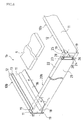
- FIG. 41 is a partial exploded perspective view showing the structure of a solar cell module 3 according to a conventional example using such a frame member
- FIG. 42 is a partial plan view thereof
- FIG. 43 is a cross-sectional view taken along G-G in FIG. 42
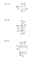
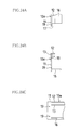
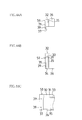
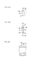
- FIGS. 44A to 44C , and FIGS. 45A to 45C are drawings showing the shapes of edge portions of a main frame member 50 and a sub-frame member 60 that are used for this solar cell module 3.
- FIGS. 44A and 45A are partial plan views
- FIGS. 44B and 45B are front views
- FIGS. 44C and 45C are partial side views, respectively.
- a solar cell panel 9 is omitted in FIGS. 42 and 43 .
- the solar cell module 3 according to this conventional example has the following structure. That is, in FIGS. 41 to 45C , the solar cell panel 9 has a rectangular shape, and using two pairs of members, each pair constituted from the main frame member 50 that holds one side of this solar cell panel 9 and the sub-frame member 60 that holds an adjoining side that adjoins this one side, the solar cell panel 9 is held.
- the above-mentioned main frame member 50 is constituted from a main outer wall 31, a main holding upper piece 32, a main holding lower piece 33, a main base piece 34, a main inner wall 35, and a main bottom piece 36.
- the main outer wall 31 is perpendicularly formed along one side of the solar cell panel 9.
- the main holding upper piece 32 and the main holding lower piece 33 are provided projecting horizontally with substantially the same length, above and below, to the inner side of the upper part of the above-mentioned main outer wall 31, and hold the solar cell panel 9 fitted therebetween.
- the main base piece 34 is formed projecting horizontally, on the inner side of the lower edge of the main outer wall 31, along this main outer wall 31.
- the main inner wall 35 is formed parallel to the main outer wall 31, connecting the edge of the main base piece 34 and the edge of the main holding lower piece 33.
- the main bottom piece 36 is formed on the inner side of the lower edge of the main inner wall 35, along the main inner wall 35, projecting horizontally further than the main holding upper piece 32 and the main holding lower piece 33.
- the sub-frame member 60 is constituted similarly to the above-mentioned main frame member 50, and is constituted from a sub-outer wall 41, a sub-holding upper piece 42, a sub-holding lower piece 43, a sub-base piece 44, a sub-inner wall 45, and a sub-bottom piece 46 as shown in FIGS. 45A to 45C .
- the sub-outer wall 41 is perpendicularly formed along an adjoining side that adjoins the above-mentioned one side of the solar cell panel 9.
- the sub-holding upper piece 42 and the sub-holding lower piece 43 are provided projecting horizontally with substantially the same length, above and below, to the inner side of the upper part of the above-mentioned sub-outer wall 41, and hold the solar cell panel 9 fitted therebetween.
- the sub-base piece 44 is formed projecting horizontally, on the inner side of the lower edge of the sub-outer wall 41, along this sub-outer wall 41.
- the sub-inner wall 45 is formed parallel to the sub-outer wall 41, connecting the edge of the sub-base piece 44 and the edge of the sub-holding lower piece 43.
- the sub-bottom piece 46 is formed on the inner side of the lower edge of the sub-inner wall 45, along the sub-inner wall 45, projecting horizontally further than the sub-holding upper piece 42 and the sub-holding lower piece 43. Using this sub-bottom piece 46 similarly to the main bottom piece 36, this solar cell module 3 is fixed when installed. That is, similar to the main bottom piece 36, using mounting holes provided to the sub-bottom piece 46, the solar cell module 3 is fixed with bolts, for instance.
- the main bottom piece 36 of the main frame member 30 is formed projecting from the lower edge of the main inner wall 35 to the inner side, and also the sub-bottom piece 46 of the sub-frame member 40 is formed projecting from the lower edge of the sub-inner wall 45 to the inner side, respectively. Therefore, in this state, if it is attempted to cause the sides of the solar cell panel 9 to be fitted in the main frame member 30 and the sub-frame member 40, the main bottom piece 36 and the sub-bottom piece 46 collide, so that the main frame member 30 and the sub-frame member 40 cannot be connected. Accordingly, the solar cell module 3 cannot be formed.
- a sub-inner wall edge portion inner side surface 47 is formed on which the sub-bottom piece 46 is not projecting from the lower edge of the sub-inner wall 45, on the inner side of the edge portion of the sub-outer wall 41 (see FIGS. 41 , and 45A to 45C).
- an edge portion end surface 6a of the edge portion of the sub-frame member 60 is abutted against the main outer wall edge portion inner side surface 37 of the main frame member 50.
- the end surface of the main holding upper piece 32 of the main frame member 50 is abutted against the edge surface of the sub-holding upper piece 42 of the sub-frame member 60, and the end surfaces of the main holding lower piece 33, the main base piece 34, the main inner wall 35, and the main bottom piece 36 of the main frame member 50 are abutted against the sub-inner wall edge portion inner side surface 47 of the sub-frame member 60.
- the main frame member 50 and the sub-frame member 60 are connected via screws using screw holes 39 and screw receptacles 48, thus forming the solar cell module 3 (see FIGS. 41 to 43 ).
- the present invention has been conceived in order to improve such circumstances.
- a solar cell module that is formed by abutting an edge portion of a sub-frame member against an edge portion of a main frame member so as to connect the main frame member and the sub-frame member
- the present invention is aimed at providing a solar cell module that can be constituted using a frame member with a bottom piece of the frame member projecting from the lower edge of the frame member toward the solar cell panel side (inner side) that is used for fixing the solar cell module and, also, needing the edge portion of only either the main frame member or the sub-frame member to be cut.
- a first solar cell module of the present invention is a solar cell module that holds a solar cell panel using a plurality of pairs of members, each pair constituted from a main frame member that holds one side of the solar cell panel and a sub-frame member that holds an adjoining side that adjoins the one side.
- the above-mentioned main frame member is constituted from a main outer wall, a main holding upper piece, a main holding lower piece, and a main bottom piece.
- the main outer wall is formed along one side of the solar cell panel.
- the main holding upper piece and the main holding lower piece are provided projecting inward, above and below, to an inner side of an upper part of the main outer wall, and has a function of holding the solar cell panel fitted therebetween.
- the main bottom piece is formed on an inner side of the main outer wall below the main holding lower piece along the main outer wall, projecting further inward than the main holding upper piece and the main holding lower piece.
- the above-mentioned sub-frame member is constituted from a sub-outer wall, a sub-holding upper piece, a sub-holding lower piece, a sub-base piece, a sub-inner wall, and a sub-bottom piece.
- the sub-outer wall is formed along the adjoining side of the solar cell panel.
- the sub-holding upper piece and the sub-holding lower piece are provided projecting inward, above and below, to an inner side of an upper part of the sub-outer wall, and has a function of holding the solar cell panel fitted therebetween.
- the sub-base piece is formed projecting inward on an inner side of a lower edge of the sub-outer wall along the sub-outer wall.
- the sub-inner wall is formed parallel to the sub-outer wall connecting the sub-base piece and the sub-holding lower piece.
- the sub-bottom piece is formed on an inner side of the sub-inner wall along the sub-inner wall, projecting further inward than the sub-holding upper piece and the sub-holding lower piece.
- first solar cell module by removing the main holding upper piece and the main holding lower piece in an edge portion of the main outer wall of the main frame member from an end edge of the main outer wall, for substantially a same width as a projecting length of the sub-holding upper piece and the sub-holding lower piece of the sub-frame member, a flat main outer wall edge portion inner side surface is formed on an inner side of the edge portion of the main outer wall, and an end surface of an edge portion of the sub-frame member is abutted against the main outer wall edge portion inner side surface, connecting the main frame member and the sub-frame member.
- the main bottom piece of the main frame member and the sub-bottom piece of the sub-frame member are formed so as not to collide with each other, such that the projecting position heights of the main bottom piece and the sub bottom piece are different.
- the main bottom piece of the main frame member and the sub-bottom piece of the sub-frame member are formed so as not to collide with each other, such that the projecting position heights of the pieces are different.
- the solar cell module can be constituted using a frame member with a bottom piece of the frame member projecting from the lower edge of the frame member toward the solar cell panel side (inner side) that is used for fixing the solar cell module and, also, needing the edge portion of only either the main frame member or the sub-frame member to be cut.
- a second solar cell module of the present invention is a solar cell module that holds a solar cell panel using a plurality of pairs of members, each pair constituted from a main frame member that holds one side of the solar cell panel, and a sub-frame member that holds an adjoining side that adjoins this one side.
- the above-mentioned main frame member is constituted from a main outer wall, a main holding upper piece, a main holding lower piece, and a main bottom piece, similar to the above-mentioned first solar cell module.
- the main outer wall is formed along one side of the solar cell panel.
- the main holding upper piece and the main holding lower piece are provided projecting inward, above and below, to an inner side of an upper part of the main outer wall, and has a function of holding the solar cell panel fitted therebetween.
- the main bottom piece is formed on an inner side of the main outer wall below the main holding lower piece along the main outer wall, projecting further inward than the main holding upper piece and the main holding lower piece.
- the above-mentioned sub-frame member is constituted from a sub-outer wall, a sub-holding upper piece, a sub-holding lower piece, and a sub-bottom piece.
- the sub-outer wall is formed along the adjoining side of the solar cell panel.
- the sub-holding upper piece and the sub-holding lower piece are provided projecting inward, above and below, to an inner side of an upper part of the sub-outer wall, and has a function of holding the solar cell panel fitted therebetween.
- the sub-bottom piece is formed on an inner side of the sub-outer wall below the sub-holding lower piece along the sub-outer wall, projecting further inward than the sub-holding upper piece and the sub-holding lower piece.
- the main bottom piece of the main frame member and the sub-bottom piece of the sub-frame member are formed so as not to collide with each other, such that the projecting position heights of the main bottom piece and the sub-bottom piece are different.
- the main bottom piece of the main frame member and the sub-bottom piece of the sub-frame member are formed so as not to collide with each other, such that the projecting position heights of the pieces are different.
- the solar cell module can be constituted using a frame member with a bottom piece of the frame member projecting from the lower edge of the frame member toward the solar cell panel side (inner side) that is used for fixing the solar cell module and, also, needing the edge portion of only either the main frame member or the sub-frame member to be cut.
- the main bottom piece of the main frame member may be formed projecting on an inner side of a lower edge of the main outer wall, and the solar cell module may be fixed using the main bottom piece when installed.
- the sub-bottom piece of the sub-frame member may be formed projecting inward, so as to be positioned above the main bottom piece. In this way, when connecting the main frame member and the sub-frame member, it is possible to avoid the main bottom piece of the main frame member and the sub-bottom piece of the sub-frame member colliding with each other.
- first solar cell module or second solar cell module that is, the solar cell module with the main bottom piece of the main frame member being formed projecting on the inner side of the lower edge of the main outer wall, the main bottom piece being used for fixing the solar cell module when installed, and the sub-bottom piece of the sub-frame member being formed projecting inward so as to be positioned above the main bottom piece.
- a protrusion for reinforcement is formed on a joint at which the main bottom piece of the main frame member projects from the lower edge of the main outer wall, and the sub-bottom piece of the sub-frame member is formed projecting inward so as to be positioned above the protrusion for reinforcement, in order not to collide with the protrusion for reinforcement.
- first solar cell module or second solar cell module that is, the solar cell module with the main bottom piece of the main frame member being formed projecting on the inner side of the lower edge of the main outer wall, the main bottom piece being used for fixing the solar cell module when installed, and the sub-bottom piece of the sub-frame member being formed projecting inward so as to be positioned above the main bottom piece.
- the sub-bottom piece of the sub-frame member is formed such that a lower surface near a side end of the sub-bottom piece abuts against an upper surface near a side end of the main bottom piece of the main frame member.
- gravity on the sub-frame member can be transferred to the main bottom piece that is formed at the lower edge of the main outer wall, and that is used for fixing the solar cell module when installed. Accordingly, the above-mentioned first solar cell module or second solar cell module can be stably installed.
- the sub-bottom piece of the sub-frame member is formed projecting on an inner side of a lower edge of the sub-inner wall with the above-mentioned first solar cell module, and is formed projecting on an inner side of a lower edge of the sub-outer wall with the above-mentioned second solar cell module, and the solar cell module is fixed using the sub-bottom piece when installed.
- the main bottom piece of the main frame member is formed projecting on the inner side of the main outer wall, so as to be positioned above the sub-bottom piece.
- the main bottom piece of the main frame member may be formed such that a lower surface near a side end of the main bottom piece abuts against an upper surface near a side end of the sub-bottom piece of the sub-frame member.
- This improved solar cell module is a solar cell module that holds a solar cell panel using a plurality of pairs of members, each pair constituted from a main frame member that holds one side of the solar cell panel, and a sub-frame member that holds an adjoining side that adjoins the one side, similar to the above-mentioned solar cell module.
- the above-mentioned main frame member is constituted from a main outer wall, a main holding upper piece, a main holding lower piece, a main base piece, a main inner wall, and a main bottom piece.
- the main outer wall is formed along one side of the solar cell panel.
- the main holding upper piece and the main holding lower piece are provided projecting inward, above and below, to an inner side of an upper part of the main outer wall, and has a function of holding the solar cell panel fitted therebetween.
- the main base piece is formed projecting inward, on an inner side of a lower edge of the main outer wall along the main outer wall.
- the main inner wall is formed so as to be formed parallel to the main outer wall, connecting the main base piece and the main holding lower piece.
- the main bottom piece is formed on an inner side of a lower edge of the main inner wall along the main inner wall, projecting further inward than the main holding upper piece and the main holding lower piece.
- the above-mentioned sub-frame member is constituted in a substantially similar manner to the above-mentioned main frame member, and is constituted from a sub-outer wall, a sub-holding upper piece, a sub-holding lower piece, a sub-base piece, a sub-inner wall, and a sub-bottom piece.
- the sub-outer wall is formed along the adjoining side of the solar cell panel.
- the sub-holding upper piece and the sub-holding lower piece are provided projecting inward, above and below, to an inner side of an upper part of the sub-outer wall, and has a function of holding the solar cell panel fitted therebetween.
- the sub-base piece is formed projecting inward on an inner side of a lower edge of the sub-outer wall along the sub-outer wall.
- the sub-inner wall is formed parallel to the sub-outer wall, connecting the sub-base piece and the sub-holding lower piece.
- the sub-bottom piece is formed on an inner side of the sub-inner wall along the sub-inner wall, projecting further inward than the sub-holding upper piece and the sub-holding lower piece.
- the solar cell module it is preferable to fix the solar cell module using the main bottom piece of the main frame member when installed.
- a flat main outer wall edge portion inner side surface is formed on an inner side of the edge portion of the main outer wall. Then, an end surface of an edge portion of the sub-frame member is abutted against the main outer wall edge portion inner side surface, connecting the main frame member and the sub-frame member.
- the sub-bottom piece of the sub-frame member is formed projecting on the inner side of the sub-inner wall, so as to be positioned above the main bottom piece of the main frame member, and in the main inner wall, a slit that has a same length as a projecting length of the sub-bottom piece is formed at a same height position as a projecting position of the sub-bottom piece, and when the main frame member and the sub-frame member are connected, the above-mentioned sub-bottom piece is inserted into the slit.
- the sub-bottom piece of the sub-frame member is formed projecting on the inner side of the sub-inner wall, so as to be positioned above the main bottom piece of the main frame member, and in the main inner wall, a slit that has the same length as the projecting length of the sub-bottom piece is formed at the same height position as the projecting position of the sub-bottom piece, and when the main frame member and the sub-frame member are connected, the above-mentioned sub-bottom piece is inserted into the slit.
- a slit that has the same length as the projecting length of the sub-bottom piece is formed at the same height position as the projecting position of the sub-bottom piece, and when the main frame member and the sub-frame member are connected, the above-mentioned sub-bottom piece is inserted into the slit.
- the flat main outer wall edge portion inner side surface is formed on the inner side of the edge portion of the main outer wall. Then, the end surface of the edge portion of the sub-frame member is abutted against the main outer wall edge portion inner side surface, and the main frame member and the sub-frame member are connected. That is, if only the main outer wall edge portion inner side surface is formed by cutting the edge portion of the main outer wall of the main frame member, it is possible to connect the main frame member and the sub-frame member.
- the solar cell module that is formed by abutting the edge portion of the sub-frame member against the edge portion of the main frame member so as to connect the main frame member and the sub-frame member, it is possible to constitute a solar cell module that can be constituted using a frame member with a bottom piece of the frame member projecting from the lower edge of the frame member toward the inner side that is used for fixing the solar cell module and, also, needing the edge portion of only either the main frame member or the sub-frame member to be cut.
- a main bottom piece of a main frame member, and a sub-bottom piece of a sub-frame member are formed so as not to collide with each other, such that the projecting position heights of the pieces are different. Accordingly, if only a main outer wall edge portion inner side surface is formed by cutting the edge portion of a main outer wall of the main frame member, it is possible to connect the main frame member and the sub-frame member.
- the solar cell module that is formed by abutting the edge portion of the sub-frame member against the edge portion of the main frame member so as to connect the main frame member and the sub-frame member
- the solar cell module can be constituted using a frame member with a bottom piece of the frame member projecting from the lower edge of the frame member toward the inner side that is used for fixing the solar cell module and, also, needing the edge portion of only the main frame member to be cut, among the main frame member and the sub-frame member.
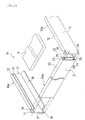
- FIG. 1 is a partial exploded perspective view showing the structure of a solar cell module 1a according to Embodiment 1
- FIG. 2 is a partial plan view thereof
- FIG. 3 is a cross-sectional view taken along A-A in FIG. 2
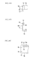
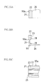
- FIGS. 4A to 4C , and FIGS. 5A to 5C are drawings showing the shapes of edge portions of a main frame member 10a and a sub-frame member 20a that are used for this solar cell module 1a.
- FIGS. 4A and 5A are partial plan views
- FIGS. 4B and 5B are front views
- FIGS. 4C and 5C are partial side views. Note that a solar cell panel 9 is omitted in FIGS. 2 and 3 .
- the solar cell module 1a according to Embodiment 1 has the following structure. That is, in FIGS. 1 to 5C , the solar cell panel 9 has a rectangular shape, and using two pairs of members, each pair constituted from the main frame member 10a that holds one side of this solar cell panel 9, and the sub-frame member 20a that holds an adjoining side that adjoins this one side, the solar cell panel 9 is held.
- the above-mentioned main frame member 10a is constituted from a main outer wall 11, a main holding upper piece 12, a main holding lower piece 13, and a main bottom piece 16.
- the main outer wall 11 is perpendicularly formed along one side of the solar cell panel 9 that is in a horizontal state.
- the main holding upper piece 12 and the main holding lower piece 13 are provided projecting horizontally with substantially the same length, above and below, to the inner side of the upper part of the main outer wall 11, and hold the solar cell panel 9 fitted therebetween.
- the main bottom piece 16 is formed on the inner side of the lower edge of the main outer wall 11, along the main outer wall 11, projecting horizontally further than the main holding upper piece 12 and the main holding lower piece 13.
- the above-mentioned sub-frame member 20a is constituted from a sub-outer wall 21, a sub-holding upper piece 22, a sub-holding lower piece 23, a sub-base piece 24, a sub-inner wall 25, and a sub-bottom piece 26.
- the sub-outer wall 21 is perpendicularly formed along an adjoining side that adjoins the above-mentioned one side of the solar cell panel 9.
- the sub-holding upper piece 22 and the sub-holding lower piece 23 are provided projecting horizontally with substantially the same length, above and below, to the inner side of the upper part of the sub-outer wall 21, and hold the solar cell panel 9 fitted therebetween.
- the sub-base piece 24 is formed projecting horizontally on the inner side of the lower edge of the sub-outer wall 21, along the sub-outer wall 21.
- the sub-inner wall 25 is formed parallel to the sub-outer wall 21 connecting the sub-base piece 24 and the sub-holding lower piece 23.
- the sub-bottom piece 26 is formed on the inner side of the lower part of the sub-inner wall 25, along the sub-inner wall 25, projecting horizontally further than the sub-holding upper piece 22 and the sub-holding lower piece 23.
- the main bottom piece 16 of the main frame member 10a is formed projecting on the inner side of the lower edge of the main outer wall 11, and using the main bottom piece 16, the solar cell module 1a is fixed when installed.
- the sub-bottom piece 26 of the sub-frame member 20a is formed projecting on the inner side of the sub-inner wall 25 of the sub-frame member 20a, so as to be positioned above the main bottom piece 16 of the main frame member 10a.
- the sub-bottom piece 26 of the sub-frame member 20a is formed projecting on the inner side of the sub-inner wall 25 of the sub-frame member 20a, so as to be positioned above the main bottom piece 16 of the main frame member 10a as described above, it is possible to connect the main bottom piece 16 of the main frame member 10a, and the sub-bottom piece 26 of the sub-frame member 20a so as not to collide with each other.
- the main bottom piece 16 of the main frame member 10a and the sub-bottom piece 26 of the sub-frame member 20a are formed so as not to collide with each other, such that the projecting position heights of the pieces are different, that is, such that the sub-bottom piece 26 of the sub-frame member 20a is positioned above the main bottom piece 16 of the main frame member 10a.
- the main bottom piece 16 of the main frame member 10a is used for fixing the solar cell module 1a. Therefore, regarding the solar cell module 1a that is formed by abutting the edge portion of the sub-frame member 20a against the edge portion of the main frame member 10a so as to connect the main frame member 10a and the sub-frame member 20a, the solar cell module 1a can be constituted using a frame member with a bottom piece of the frame member projecting from the lower edge of the frame member toward the solar cell panel 9 side (inner side) that is used for fixing this solar cell module 1a (the main bottom piece 16 of the main frame member 10a) and, also, needing the edge portion of only the main frame member 10a to be cut, which is one of the main frame member 10a and the sub-frame member 20a.
- FIG. 6 is a partial exploded perspective view showing the structure of a solar cell module 1b according to Embodiment 2
- FIG. 7 is a partial plan view thereof
- FIG. 8 is a cross-sectional view taken along B-B in FIG. 7
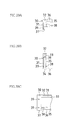
- FIGS. 9A to 9C , and FIGS. 10A to 10C are drawings showing the shapes of edge portions of a main frame member 10b and a sub-frame member 20b that are used for this solar cell module 1b.
- FIGS. 9A and 10A are partial plan views
- FIGS. 9B and 10B are front views
- FIGS. 9C and 10C are partial side views. Note that a solar cell panel 9 is omitted in FIGS. 7 and 8 .
- the solar cell module 1b according to Embodiment 2 is almost the same as the solar cell module 1a according to Embodiment 1, and the following points are modified from the solar cell module 1a according to Embodiment 1.
- a reinforcement lump 18 that is a protrusion for reinforcement is formed on the joint at which the main bottom piece 16 of the main frame member 10b projects from the lower edge of the main outer wall 11, and the sub-bottom piece 26 of the sub-frame member 20b is formed projecting on the inner side of the sub-inner wall 25 of the sub-frame member 20b so as to be positioned above the reinforcement lump 18 so that the sub-bottom piece 26 does not collide with this reinforcement lump 18 for reinforcement.
- the strength of the main frame member 10b can be increased.
- the sub-bottom piece 26 of the sub-frame member 20b is formed projecting on the inner side of the sub-inner wall so as to be positioned above the reinforcement lump 18 for reinforcement, it is possible to avoid the sub-bottom piece of the sub-frame member colliding with the protrusion for reinforcement.
- FIG. 11 is a partial exploded perspective view showing the structure of a solar cell module 1c according to Embodiment 2
- FIG. 12 is a partial plan view thereof
- FIG. 13 is a cross-sectional view taken along C-C in FIG. 12
- FIGS. 14A to 14C , and FIGS. 15A to 15C are drawings showing the shapes of edge portions of a main frame member 10c and a sub-frame member 20c that are used for this solar cell module 1c.
- FIGS. 14A and 15A are partial plan views
- FIGS. 14B and 15B are front views
- FIGS. 14C and 15C are partial side views. Note that a solar cell panel 9 is omitted in FIGS. 12 and 13 .
- the solar cell module 1c according to Embodiment 3 is almost the same as the solar cell module 1a according to Embodiment 1. That is, in FIGS. 11 to 15C , the main bottom piece 16 of the main frame member 10c is formed projecting on the inner side of the lower edge of the main outer wall 11, and using the main bottom piece 16, the solar cell module 1c is fixed when installed. Also, the sub-bottom piece 26 of the sub-frame member 20c is formed projecting on the inner side of the sub-inner wall 25 of the sub-frame member 20c so as to be positioned above the main bottom piece 16 of the main frame member 10c, which is similar to the solar cell module 1a according to Embodiment 1.
- the sub-bottom piece 26 of the sub-frame member 20c is formed such that the lower surface near the side end of the sub-bottom piece 26 abuts against the upper surface near the side end of the main bottom piece 16 of the main frame member 10c.
- gravity on the sub-frame member 20c can be transferred to the main bottom piece 16 of the main frame member 10c that is formed at the lower edge of the main outer wall 11 of the main frame member 10c, and that is used for fixing the solar cell module 1c when installed. Accordingly, the above-mentioned solar cell module 1c can be stably installed.
- FIG. 16 is a partial exploded perspective view showing the structure of a solar cell module 1d according to Embodiment 4,
- FIG. 17 is a partial plan view thereof
- FIG. 18 is a cross-sectional view taken along D-D in FIG. 17 .
- FIGS. 19A to 19C , and FIGS. 20A to 20C are drawings showing the shapes of edge portions of a main frame member 10d and a sub-frame member 20d that are used for this solar cell module 1d.
- FIGS. 19A and 20A are partial plan views
- FIGS. 19B and 20B are front views
- FIGS. 19C and 20C are partial side views. Note that a solar cell panel 9 is omitted in FIGS. 17 and 18 .
- the solar cell module 1d according to Embodiment 4 is almost the same as the solar cell module 1a according to Embodiment 1, and the following point is modified from the solar cell module 1a according to Embodiment 1.
- the solar cell module 1d according to Embodiment 4 is constituted such that the roles of the main frame member 10d and the sub-frame member 20d are the opposites of the roles of the main frame member 10a and the sub-frame member 20a of the solar cell module 1a according to Embodiment 1.
- the sub-bottom piece 26 of the sub-frame member 20d is formed projecting on the inner side of the lower edge of the sub-inner wall 25 of the sub-frame member 20d, and using the sub-bottom piece 26, the solar cell module 1d is fixed when installed.
- the main bottom piece 16 of the main frame member 10d is formed projecting on the inner side of the main outer wall 11 of the main frame member 10d so as to be positioned above the sub-bottom piece 26 of the sub-frame member 20d.
- the function and effect provided to the solar cell module 1d according to Embodiment 4 are the same as the function and effect provided to the solar cell module 1a according to Embodiment 1.
- FIG. 21 is a partial exploded perspective view showing the structure of a solar cell module 1e according to Embodiment 5
- FIG. 22 is a partial plan view thereof
- FIG. 23 is a cross-sectional view taken along E-E in FIG. 22
- FIGS. 24A to 24C , and FIGS. 25A to 25C are drawings showing the shapes of edge portions of a main frame member 10e and a sub-frame member 20e that are used for this solar cell module 1e.
- FIGS. 24A and 25A are partial plan views
- FIGS. 24B and 25B are front views
- FIGS. 24C and 25C are partial side views. Note that a solar cell panel 9 is omitted in FIGS. 22 and 23 .
- the solar cell module 1e according to Embodiment 5 is almost the same as the solar cell module 1d according to Embodiment 4. That is, in FIGS. 21 to 25C , the sub-bottom piece 26 of the sub-frame member 20e is formed projecting on the inner side of the lower edge of the sub-inner wall 25 of the sub-frame member 20e, and using the sub-bottom piece 26, the solar cell module 1e is fixed when installed. Further, the main bottom piece 16 of the main frame member 10e is formed projecting on the inner side of the main outer wall 11 of the main frame member 10e so as to be positioned above the sub-bottom piece 26 of the sub-frame member 20e, which is similar to the solar cell module 1d according to Embodiment 4.
- the sub-bottom piece 26 of the sub-frame member 20e is formed such that the upper surface near the side end of the sub-bottom piece 26 abuts against the lower surface near the side end of the main bottom piece 16 of the main frame member 10e.
- gravity on the sub-frame member 20e can be transferred to the main bottom piece 16 of the main frame member 10e that is formed at the lower edge of the main outer wall 11 of the main frame member 10e, and that is used for fixing the solar cell module 1e when installed. Accordingly, the above-mentioned solar cell module 1e can be stably installed.
- FIG. 26 is a partial exploded perspective view showing the structure of a solar cell module 4a according to Embodiment 6,
- FIG. 27 is a partial plan view thereof
- FIG. 28 is a cross-sectional view taken along H-H in FIG. 27 .
- FIGS. 29A to 29C , and FIGS. 30A to 30C are drawings showing the shapes of edge portions of a main frame member 10a and a sub-frame member 70a that are used for this solar cell module 4a.
- FIGS. 29A and 30A are partial plan views
- FIGS. 29B and 30B are front views
- FIGS. 29C and 30C are partial side views. Note that a solar cell panel 9 is omitted in FIGS. 27 and 28 .
- the solar cell module 4a according to Embodiment 6 has the following structure. That is, in FIGS. 26 to FIG. 30C , the solar cell panel 9 has a rectangular shape, and using two pairs of members, each pair constituted from the main frame member 10a that holds one side of this solar cell panel 9 and the sub-frame member 70a that holds an adjoining side that adjoins this one side, the solar cell panel 9 is held.
- the above-mentioned main frame member 10a is constituted from a main outer wall 11, a main holding upper piece 12, a main holding lower piece 13, and a main bottom piece 16.
- the main outer wall 11 is formed along one side of the solar cell panel 9.
- the main holding upper piece 12 and the main holding lower piece 13 are provided projecting horizontally with substantially the same length, above and below, to the inner side of the upper part of the main outer wall 11, and hold the solar cell panel 9 fitted therebetween.
- the main bottom piece 16 is formed on the inner side of the lower edge of the main outer wall 11, along the main outer wall 11, projecting horizontally further than the main holding upper piece 12 and the main holding lower piece 13.
- the above-mentioned sub-frame member 70a is constituted from the sub-outer wall 21, the sub-holding upper piece 22, the sub-holding lower piece 23, and the sub-bottom piece 26.
- the sub-outer wall 21 is perpendicularly formed along an adjoining side that adjoins the above-mentioned one side of the solar cell panel 9.
- the sub-holding upper piece 22 and the sub-holding lower piece 23 are provided projecting horizontally with substantially the same length, above and below, to the inner side of the upper part of the sub-outer wall 21, and hold the solar cell panel 9 fitted therebetween.
- the sub-bottom piece 26 is formed on the inner side of the lower part of the sub-outer wall 21, along the sub-outer wall 21, projecting horizontally further than the sub-holding upper piece 22 and the sub-holding lower piece 23.
- the main bottom piece 16 of the main frame member 10a is formed projecting on the inner side of the lower edge of the main outer wall 11, and using the main bottom piece 16, the solar cell module 4a is fixed when installed. Further, the sub-bottom piece 26 of the sub-frame member 70a is formed projecting on the inner side of the sub-outer wall 21 of the sub-frame member 70a so as to be positioned above the main bottom piece 16 of the main frame member 10a.
- the sub-bottom piece 26 of the sub-frame member 70a is formed projecting on the inner side of the sub-outer wall 21 of the sub-frame member 70a, so as to be positioned above the main bottom piece 16 of the main frame member 10a as described above, it is possible to connect the main bottom piece 16 of the main frame member 10a and the sub-bottom piece 26 of the sub-frame member 70a so as not to collide with each other.
- the main bottom piece 16 of the main frame member 10a and the sub-bottom piece 26 of the sub-frame member 70a are formed so as not to collide with each other, such that the projecting position heights of the pieces are different, that is, such that the sub-bottom piece 26 of the sub-frame member 70a is positioned above the main bottom piece 16 of the main frame member 10a.
- the main bottom piece 16 of the main frame member 10a is used for fixing the solar cell module 4a. Therefore, regarding the solar cell module 4a that is formed by abutting the edge portion of the sub-frame member 70a against the edge portion of the main frame member 10a so as to connect the main frame member 10a and the sub-frame member 70a, the solar cell module 4a can be constituted using a frame member with a bottom piece of the frame member projecting from the lower edge of the frame member toward the solar cell panel 9 side (inner side) that is used for fixing this solar cell module 4a (the main bottom piece 16 of the main frame member 10a) and, also, needing the edge portion of only the main frame member 10a to be cut, which is one of the main frame member 10a and the sub-frame member 70a.
- the solar cell module 1b to the solar cell module 1e according to Embodiments 2 to 5 that have been described above can be said to be modified examples of the solar cell module 1a according to Embodiment 1. That is, the solar cell modules 1b to 1e according to Embodiments 2 to 5 that have been described above are constituted by changing the shape of the main frame member 10a of the solar cell module 1a according to Embodiment 1 to the shapes of the main frame members 10b to 10e, respectively and, also, by changing the shape of the sub-frame member 20a to the shapes of the sub-frame members 20b to 20e, respectively.
- FIG. 31 is a partial exploded perspective view showing the structure of a solar cell module 5a according to Embodiment 7, FIG. 32 is a partial plan view thereof, and FIG. 33 is a cross-sectional view taken along J-J in FIG. 32 .
- FIGS. 34A to 34C , and FIGS. 35A to 35C are drawings showing the shapes of edge portions of a main frame member 80a and a sub-frame member 90a that are used for this solar cell module 5a.
- FIGS. 34A and 35A are partial plan views
- FIGS. 34B and 35B are front views
- FIGS. 34C and 35C are partial side views, respectively. Note that a solar cell panel 9 is omitted in FIGS. 32 and 33 .
- the basic structure of the solar cell module 5a according to Embodiment 7 is the same as that of the solar cell module 4a according to Embodiment 6.
- the solar cell module 5a according to Embodiment 7 differs from the solar cell module 4a according to Embodiment 6 in that the main frame member 80a is used instead of the main frame member 10a, and the sub-frame member 90a is used instead of the sub-frame member 70a.
- the main frame member 80a is constituted from a main outer wall 11, a main holding upper piece 12, a main holding lower piece 13, and a main bottom piece 16.
- the main outer wall 11 is perpendicularly formed along one side of the solar cell panel 9.
- the main holding upper piece 12 and the main holding lower piece 13 are provided projecting horizontally with substantially the same length, above and below, to the inner side of the upper part of the main outer wall 11, and hold the solar cell panel 9 fitted therebetween.
- main frame member 80a is provided with screw holes 19 that are used for connecting the main frame member 80a and the sub-frame member 90a
- a screw hole disposition wall 81 that is a portion of the main frame member 80a in the vicinity of the screw holes 19 provided is depressed inward for the amount corresponding to the thickness of the screw head of a pan head screw to be fitted in the screw hole 19, relative to other portions of the main frame member 80a. Accordingly, when the main frame member 80a and the sub-frame member 90a are connected, the head of the screw used for this connection does not jut outward, relative to the position of the outer surface of the above-mentioned other portions of the main frame member 80a.
- the top of the main outer wall 11 of the main frame member 80a is formed so as to be roundish, and the inner side edge of the main holding upper piece 12 is formed so as to be inwardly inclined aslant. Accordingly, when it is raining, even though the solar cell module 5a becomes wet in the rain, drainage with this solar cell module 5a can be improved.
- the sub-frame member 90a is constituted from a sub-outer wall 21, a sub-holding upper piece 22, a sub-holding lower piece 23, and a sub-bottom piece 26.
- the sub-outer wall 21 is perpendicularly formed along an adjoining side that adjoins the above-mentioned one side of the solar cell panel 9.
- the sub-holding upper piece 22 and the sub-holding lower piece 23 are provided projecting horizontally with substantially the same length, above and below, to the inner side of the upper part of the sub-outer wall 21, and hold the solar cell panel 9 fitted therebetween.
- the sub-bottom piece 26 is formed on the inner side of the lower part of the sub-outer wall 21, along the sub-outer wall 21, projecting horizontally further than the sub-holding upper piece 22 and the sub-holding lower piece 23.
- the main bottom piece 16 of the main frame member 80a is formed projecting on the inner side of the lower edge of the main outer wall 11, and using the main bottom piece 16, the solar cell module 5a is fixed when installed.
- the sub-bottom piece 26 of the sub-frame member 90a is formed projecting on the inner side of the sub-outer wall 21 of the sub-frame member 90a so as to be positioned above the main bottom piece 16 of the main frame member 80a.
- the sub-bottom piece 26 of the sub-frame member 90a is formed projecting on the inner side of the sub-outer wall 21 of the sub-frame member 90a, so as to be positioned above the main bottom piece 16 of the main frame member 80a as described above, it is possible to connect the main bottom piece 16 of the main frame member 80a, and the sub-bottom piece 26 of the sub-frame member 90a so as not to collide with each other.
- the lower portion of the sub-outer wall 21 of the sub-frame member 90a below the sub-holding lower piece 23 is depressed inward relative to the upper portion, and a sub-base outer piece 91 is formed bent outward at the lower edge of the sub-outer wall 21.
- the sub-outer wall 21 of the sub-frame member 90a is formed such that the outer side edge of the sub-base outer piece 91 is in the same plane as the surface position of the upper portion of the sub-outer wall 21 of the sub-frame member 90a above the sub-holding lower piece 23.
- the solar cell module 5a can be installed such that the outer side edge of the sub-base outer piece 91 of the sub-outer wall 21 of the sub-frame member 90a adjoins that of the adjoining solar cell module 5a. Therefore, the solar cell module 5a according to Embodiment 7 can be stably installed.
- both of the load imposed on the main frame member 80a, and the load imposed on the sub-frame member 90a can be supported by the mount on which the solar cell module 5a is installed, for instance. Therefore, the solar cell module 5a can be stably installed.
- the main bottom piece 16 of the main frame member 80a and the sub-bottom piece 26 of the sub-frame member 90a are formed so as not to collide with each other, such that the projecting position heights of the pieces are different, that is, such that the sub-bottom piece 26 of the sub-frame member 90a is positioned above the main bottom piece 16 of the main frame member 80a.
- the main bottom piece 16 of the main frame member 80a is used for fixing the solar cell module 5a. Therefore, regarding the solar cell module 5a that is formed by abutting the edge portion of the sub-frame member 90a against the edge portion of the main frame member 80a so as to connect the main frame member 80a and the sub-frame member 90a, the solar cell module 5a can be constituted using a frame member with a bottom piece of the frame member projecting from the lower edge of the frame member toward the solar cell panel 9 side (inner side) that is used for fixing this solar cell module 5a (the main bottom piece 16 of the main frame member 80a) and, also, needing the edge portion of only the main frame member 80a to be cut, which is one of the main frame member 80a and the sub-frame member 90a.
- the solar cell modules 1b to 1e according to Embodiments 2 to 5 that have been described above can be said to be modified examples of the solar cell module 1a according to Embodiment 1. That is, the solar cell modules 1b to 1e according to Embodiments 2 to 5 that have been described above are constituted by changing the shape of the main frame member 10a of the solar cell module 1a according to Embodiment 1 to the shapes of the main frame members 10b to 10e, respectively and, also, by changing the shape of the sub-frame member 20a to the shapes of the sub-frame members 20b to 20e, respectively.
- FIG. 36 is a partial exploded perspective view showing the structure of a solar cell module 2 according to Embodiment 8
- FIG. 37 is a partial plan view thereof
- FIG. 38 is a cross-sectional view taken along F-F in FIG. 37
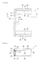
- FIGS. 39A to 39C , and FIGS. 40A to 40C are drawings showing the shapes of edge portions of a main frame member 30 and a sub-frame member 40 that are used for this solar cell module 2.
- FIGS. 39A and 40A are partial plan views
- FIGS. 39B and 40B are front views
- FIGS. 39C and 40C are partial side views, respectively. Note that a solar cell panel 9 is omitted in FIGS. 37 and 38 .
- the solar cell module 2 according to Embodiment 8 is a module obtained by improving the solar cell module 3 according to the conventional example by adopting the mechanism of the solar cell module 1a according to Embodiment 1 described above, that is, the mechanism in which, with the solar cell module 1a according to Embodiment 1 described above, the main bottom piece 16 of the main frame member 10a and the sub-bottom piece 26 of the sub-frame member 20a are formed so as not to collide with each other, such that the projecting position heights of the pieces are different, in the solar cell module 3 according to the conventional example described above.
- This improved solar cell module is the solar cell module 2 according to Embodiment 8.
- the solar cell module 2 according to Embodiment 8 holds the solar cell panel 9 using two pairs of members, each pair constituted from the main frame member 30 that holds one side of the solar cell panel 9 and the sub-frame member 40 that holds an adjoining side that adjoins this one side.
- the above-mentioned main frame member 30 is constituted from a main outer wall 31, a main holding upper piece 32, a main holding lower piece 33, a main base piece 34, a main inner wall 35, and a main bottom piece 36.
- the main outer wall 31 is perpendicularly formed along one side of the solar cell panel 9.
- the main holding upper piece 32 and the main holding lower piece 33 are provided projecting horizontally with substantially the same length, above and below, to the inner side of the upper part of the main outer wall 31, and hold the solar cell panel 9 fitted therebetween.
- the sub-base piece 34 is formed projecting horizontally on the inner side of the lower edge of the main outer wall 31, along the main outer wall 31.
- the main inner wall 35 is formed so as to be formed parallel to the main outer wall 31 connecting the edge of the main base piece 34 and the edge of the main holding lower piece 33. Then, the main bottom piece 36 is formed on the inner side of the lower edge of the main inner wall 31, along the main inner wall 31, projecting horizontally further than the main holding upper piece 32 and the main holding lower piece 33.
- the above-mentioned sub-frame member 40 is constituted in a substantially similar manner to the above-mentioned main frame member 30, and is constituted from a sub-outer wall 41, a sub-holding upper piece 42, a sub-holding lower piece 43, a sub-base piece 44, a sub-inner wall 45, and a sub-bottom piece 46.
- the sub-outer wall 41 is perpendicularly formed along the adjoining side of the solar cell panel 9.
- the sub-holding upper piece 42 and the sub-holding lower piece 43 are provided projecting horizontally with substantially the same length, above and below, to the inner side of the upper part of the sub-outer wall 41, and hold the solar cell panel 9 fitted therebetween.
- the sub-base piece 44 is formed projecting horizontally on the inner side of the lower edge of the sub-outer wall 41, along the sub-outer wall 41.
- the sub-inner wall 45 is formed parallel to the sub-outer wall 41 connecting the edge of the sub-base piece 44, and the edge of the sub-holding lower piece 43.
- the sub-bottom piece 46 is formed on the inner side of the lower part of the sub-inner wall 45, along the sub-inner wall 45, projecting horizontally further than the sub-holding upper piece 42 and the sub-holding lower piece 43.
- the solar cell module 2 is fixed when installed. Further, by removing the main holding upper piece 32, the main holding lower piece 33, the main inner wall 35, the main base piece 34, and the main bottom piece 36 in the edge portion of the main outer wall 31 of the main frame member 30 from the end edge of the main outer wall 31, only for the same width as the projecting length of the sub-holding upper piece 42, the sub-holding lower piece 43, and the sub-base piece 44 of the sub-frame member 40, a flat main outer wall edge portion inner side surface 37 is formed on the inner side of the edge portion of the main outer wall 31 of the main frame member 30. The end surface of the edge portion of the sub-frame member 40 is abutted against the main outer wall edge portion inner side surface 37, and the main frame member 30 and the sub-frame member 40 are connected via screws using screw holes 39 and screw receptacles 48.
- the sub-bottom piece 46 of the sub-frame member 40 is formed projecting on the inner side of the sub-inner wall 45 of the sub-frame member 40 so as to be positioned above the main bottom piece 36 of the main frame member 30. Also, in the main inner wall 31 of the main frame member 30, a slit 38 that has the same length as the projecting length of this sub-bottom piece 46 is horizontally formed at the same height position as the projecting position of the sub-bottom piece 46 of the sub-frame member 40, and when the main frame member 30 and the sub-frame member 40 are connected, the sub-bottom piece 46 of the above-mentioned sub-frame member 40 is inserted into the slit 38.
- the sub-bottom piece 46 of the sub-frame member 40 is formed projecting on the inner side of the sub-inner wall 45 of the sub-frame member 40 so as to be positioned above the main bottom piece 36 of the main frame member 30. Further, in the main inner wall 31 of the main frame member 30, the slit 38 having the same length as the projecting length of this sub-bottom piece 46 is horizontally formed at the same height position as the projecting position of the sub-bottom piece 46 of the sub-frame member 40, and when the main frame member 30 and the sub-frame member 40 are connected, the sub-bottom piece 46 of the above-mentioned sub-frame member 40 is inserted into this slit 38. Therefore, when connecting the main frame member 30 and the sub-frame member 40, it is possible to avoid the main bottom piece 36 of the main frame member 30 and the sub-bottom piece 46 of the sub-frame member 40 colliding with each other.
- the flat main outer wall edge portion inner side surface 37 is formed on the inner side of the edge portion of the main outer wall 31 of the main frame member 30.
- the end surface of the edge portion of the sub-frame member 40 is abutted against the main outer wall edge portion inner side surface 37, and the main frame member 30 and the sub-frame member 40 are connected. That is, if only the main outer wall edge portion inner side surface 37 is formed by cutting the edge portion of the main outer wall 31 of the main frame member 30, it is possible to connect the main frame member 30 and the sub-frame member 40.
- the solar cell module 2 that is formed by abutting the edge portion of the sub-frame member 40 against the edge portion of the main frame member 30 so as to connect the main frame member 30 and the sub-frame member 40, it is possible to constitute a solar cell module 2 that can be constituted using a frame member with a bottom piece of the frame member projecting from the lower edge of the frame member toward the inner side that is used for fixing the solar cell module 2 (the main bottom piece 36 of the main frame member 30) and, also, needing the edge portion of only the main frame member 30 to be cut, which is one of the main frame member 30 and the sub-frame member 40.
- the solar cell panel 9 may be in a perpendicular state, an inclined state, or the like, other than the horizontal state.
- all of the main holding upper piece 12 and the main holding lower piece 13 of the main frame member, and the sub-holding upper piece 22 and the sub-holding lower piece 23 of the sub-frame member have the substantially same length and are provided projecting horizontally, the length of the main holding upper piece 12, and the length of the main holding lower piece 13, or the length of the sub-holding upper piece 22 and the length of the sub-holding lower piece 23 may be different.
- the flat main outer wall edge portion inner side surface 17 is formed on the inner side of the edge portion of the main outer wall 11 of the main frame member.
- main bottom piece 16 other than the above-mentioned case, there may be a case in which depending on the shape of the sub-frame member to be connected to the main frame member, it is sufficient to remove, to an extent that the main bottom piece 16 does not interfere with this sub-frame member, a considerably shorter width than the projecting length of the sub-holding upper piece 22, the sub-holding lower piece 23, and the like of the sub-frame member from the end edge of the main outer wall 11.
- the present invention can be applied to a solar cell module that is constituted from a solar cell panel and a frame member that holds this solar cell panel.
Landscapes
- Engineering & Computer Science (AREA)
- Physics & Mathematics (AREA)
- Life Sciences & Earth Sciences (AREA)
- Sustainable Development (AREA)
- Sustainable Energy (AREA)
- Thermal Sciences (AREA)
- Chemical & Material Sciences (AREA)
- Combustion & Propulsion (AREA)
- Mechanical Engineering (AREA)
- General Engineering & Computer Science (AREA)
- Photovoltaic Devices (AREA)
- Roof Covering Using Slabs Or Stiff Sheets (AREA)
Applications Claiming Priority (2)
| Application Number | Priority Date | Filing Date | Title |
|---|---|---|---|
| JP2007228378A JP4347375B2 (ja) | 2007-09-03 | 2007-09-03 | 太陽電池モジュール |
| PCT/JP2008/065726 WO2009031518A1 (ja) | 2007-09-03 | 2008-09-02 | 太陽電池モジュール |
Publications (2)
| Publication Number | Publication Date |
|---|---|
| EP2187450A1 true EP2187450A1 (de) | 2010-05-19 |
| EP2187450A4 EP2187450A4 (de) | 2014-09-10 |
Family
ID=40428834
Family Applications (1)
| Application Number | Title | Priority Date | Filing Date |
|---|---|---|---|
| EP08829406.1A Withdrawn EP2187450A4 (de) | 2007-09-03 | 2008-09-02 | Solarzellenmodul |
Country Status (5)
| Country | Link |
|---|---|
| US (1) | US8572906B2 (de) |
| EP (1) | EP2187450A4 (de) |
| JP (1) | JP4347375B2 (de) |
| CN (1) | CN101796651B (de) |
| WO (1) | WO2009031518A1 (de) |
Cited By (1)
| Publication number | Priority date | Publication date | Assignee | Title |
|---|---|---|---|---|
| WO2017005239A1 (de) * | 2015-07-06 | 2017-01-12 | Hanwha Q Cells Gmbh | Solarmodul |
Families Citing this family (9)
| Publication number | Priority date | Publication date | Assignee | Title |
|---|---|---|---|---|
| JP2009164434A (ja) * | 2008-01-08 | 2009-07-23 | Sharp Corp | 太陽電池モジュール |
| JP4616369B2 (ja) * | 2008-06-17 | 2011-01-19 | シャープ株式会社 | 太陽電池モジュール |
| WO2012043457A1 (ja) * | 2010-09-28 | 2012-04-05 | 三洋電機株式会社 | 太陽電池モジュール |
| JP6183581B2 (ja) * | 2012-09-28 | 2017-08-23 | パナソニックIpマネジメント株式会社 | 太陽電池モジュール |
| US9397605B2 (en) * | 2013-10-30 | 2016-07-19 | Kevin Stapleton | Panel mounting bracket with under-mounting clamp and related methods |
| WO2016004474A1 (en) | 2014-07-07 | 2016-01-14 | Rockhouse International Pty Ltd | Frame systems for building structures |
| JP6667168B2 (ja) * | 2015-06-11 | 2020-03-18 | パナソニックIpマネジメント株式会社 | 太陽電池モジュールフレーム及び太陽電池モジュール |
| DE102015121615A1 (de) * | 2015-12-11 | 2017-06-14 | Hanwha Q Cells Gmbh | Solarmodul und Solarmodulrahmen |
| WO2019191691A1 (en) | 2018-03-30 | 2019-10-03 | Sunpower Corporation | Single-walled connecting key framesets |
Family Cites Families (18)
| Publication number | Priority date | Publication date | Assignee | Title |
|---|---|---|---|---|
| US4433200A (en) * | 1981-10-02 | 1984-02-21 | Atlantic Richfield Company | Roll formed pan solar module |
| US4392009A (en) * | 1981-10-16 | 1983-07-05 | Exxon Research And Engineering Co. | Solar power module |
| JPS621280A (ja) * | 1985-06-26 | 1987-01-07 | Fuji Electric Co Ltd | 太陽電池モジユ−ル |
| JP3446331B2 (ja) * | 1994-09-13 | 2003-09-16 | 鐘淵化学工業株式会社 | 太陽電池モジュールのフレーム構成部材及びこれを備えた太陽電池モジュール |
| JP3455750B2 (ja) | 1995-09-29 | 2003-10-14 | シャープ株式会社 | 太陽電池モジュールの取付け構造 |
| USRE43251E1 (en) * | 1996-09-20 | 2012-03-20 | Anderson Justin J | Frame for a wall opening and methods of assembly and use |
| JPH10308522A (ja) * | 1997-05-01 | 1998-11-17 | Kanegafuchi Chem Ind Co Ltd | 太陽電池モジュールの枠状フレーム |
| US6477816B1 (en) * | 1999-04-16 | 2002-11-12 | Frommelt Industries Of Canada, Inc. | Pit form |
| JP3754259B2 (ja) * | 2000-02-15 | 2006-03-08 | シャープ株式会社 | 太陽電池モジュール及び太陽電池モジュールの製造方法 |
| JP2002314113A (ja) | 2001-04-18 | 2002-10-25 | Asahi Kasei Corp | 太陽電池モジュール |
| JP4310940B2 (ja) * | 2001-07-05 | 2009-08-12 | 富士電機システムズ株式会社 | 太陽電池モジュールの設置方法 |
| JP4315665B2 (ja) * | 2002-10-30 | 2009-08-19 | シャープ株式会社 | 太陽電池モジュールの端面封止部材及びそれを用いた太陽電池モジュール |
| US20040144057A1 (en) * | 2003-01-27 | 2004-07-29 | Allied Tube & Conduit Corporation | Framing system for buildings |
| JP4017995B2 (ja) * | 2003-02-04 | 2007-12-05 | 株式会社タナック | パネル取り付け用のフレーム部材およびその製造方法 |
| EP1548846A3 (de) * | 2003-11-28 | 2007-09-19 | Sharp Kabushiki Kaisha | Kantenabdichtungselement für Solarzellenmodul und Solarzellenmodul mit demselben |
| JP4683955B2 (ja) * | 2004-02-25 | 2011-05-18 | 京セラ株式会社 | 太陽電池モジュールの製造方法及び太陽電池モジュールの製造用治具 |
| JP4739984B2 (ja) | 2006-02-24 | 2011-08-03 | 株式会社ハネロン | 光波長選択型可変adm装置およびそれを用いた波長多重光通信システム |
| US7797893B2 (en) * | 2006-05-11 | 2010-09-21 | Specified Technologies Inc. | Apparatus for reinforcing and firestopping around a duct extending through a structural panel |
-
2007
- 2007-09-03 JP JP2007228378A patent/JP4347375B2/ja not_active Expired - Fee Related
-
2008
- 2008-09-02 WO PCT/JP2008/065726 patent/WO2009031518A1/ja not_active Ceased
- 2008-09-02 CN CN2008801053812A patent/CN101796651B/zh not_active Expired - Fee Related
- 2008-09-02 US US12/675,201 patent/US8572906B2/en not_active Expired - Fee Related
- 2008-09-02 EP EP08829406.1A patent/EP2187450A4/de not_active Withdrawn
Cited By (1)
| Publication number | Priority date | Publication date | Assignee | Title |
|---|---|---|---|---|
| WO2017005239A1 (de) * | 2015-07-06 | 2017-01-12 | Hanwha Q Cells Gmbh | Solarmodul |
Also Published As
| Publication number | Publication date |
|---|---|
| JP2009060058A (ja) | 2009-03-19 |
| JP4347375B2 (ja) | 2009-10-21 |
| US20100243035A1 (en) | 2010-09-30 |
| CN101796651B (zh) | 2012-07-11 |
| CN101796651A (zh) | 2010-08-04 |
| US8572906B2 (en) | 2013-11-05 |
| EP2187450A4 (de) | 2014-09-10 |
| WO2009031518A1 (ja) | 2009-03-12 |
Similar Documents
| Publication | Publication Date | Title |
|---|---|---|
| US8572906B2 (en) | Solar cell module | |
| US8404966B2 (en) | Solar cell module | |
| EP2228829B1 (de) | Solarbatteriemodulvorrichtung | |
| US9188365B2 (en) | Frame for supporting solar module | |
| RU2725605C1 (ru) | Компоновка монтажной панели для коммутационного шкафа | |
| JPH11172861A (ja) | 太陽電池モジュールの取付構造 | |
| CN102884688B (zh) | 用于开关柜的壳体部件 | |
| JP5174224B2 (ja) | 太陽電池モジュール | |
| JP5299699B2 (ja) | 電気接続箱 | |
| KR102585733B1 (ko) | 태양광 패널 고정유닛과 이를 포함하는 지붕 시스템 및 그 시공방법 | |
| JP2017077389A (ja) | 連結補強具 | |
| US7044536B2 (en) | Coupling structure of hood lock stay | |
| AU2003200871B2 (en) | Connector holder | |
| CN105640056A (zh) | 组装式收纳家具 | |
| AU2022428543A1 (en) | Installation member | |
| CN105640054A (zh) | 组装式收纳家具 | |
| KR101471363B1 (ko) | 캐리어의 후드래치 장착구조 | |
| JP2013221287A (ja) | ソーラーパネル装置 | |
| RU2682955C2 (ru) | Набор грузонесущих элементов | |
| JP5288317B2 (ja) | 吊り金具用補強金具 | |
| JP5540045B2 (ja) | 太陽電池モジュールの取付け構造 | |
| JP7510320B2 (ja) | 宅配物受取容器 | |
| KR101273903B1 (ko) | 자동차용 프론트 엔드 모듈 | |
| JP5951369B2 (ja) | 太陽光パネル取付用の枠構造体、太陽光パネルの取付構造及び太陽光パネルの取付方法 | |
| KR101571661B1 (ko) | 브라켓 일체형 엔진룸 언더커버 |
Legal Events
| Date | Code | Title | Description |
|---|---|---|---|
| PUAI | Public reference made under article 153(3) epc to a published international application that has entered the european phase |
Free format text: ORIGINAL CODE: 0009012 |
|
| 17P | Request for examination filed |
Effective date: 20100212 |
|
| AK | Designated contracting states |
Kind code of ref document: A1 Designated state(s): AT BE BG CH CY CZ DE DK EE ES FI FR GB GR HR HU IE IS IT LI LT LU LV MC MT NL NO PL PT RO SE SI SK TR |
|
| AX | Request for extension of the european patent |
Extension state: AL BA MK RS |
|
| DAX | Request for extension of the european patent (deleted) | ||
| A4 | Supplementary search report drawn up and despatched |
Effective date: 20140813 |
|
| RIC1 | Information provided on ipc code assigned before grant |
Ipc: E04D 13/18 20140101ALI20140807BHEP Ipc: H01L 31/042 20140101AFI20140807BHEP |
|
| STAA | Information on the status of an ep patent application or granted ep patent |
Free format text: STATUS: THE APPLICATION IS DEEMED TO BE WITHDRAWN |
|
| 18D | Application deemed to be withdrawn |
Effective date: 20150310 |