EP2188459B1 - Entwässerungsrinne - Google Patents
Entwässerungsrinne Download PDFInfo
- Publication number
- EP2188459B1 EP2188459B1 EP08785309.9A EP08785309A EP2188459B1 EP 2188459 B1 EP2188459 B1 EP 2188459B1 EP 08785309 A EP08785309 A EP 08785309A EP 2188459 B1 EP2188459 B1 EP 2188459B1
- Authority
- EP
- European Patent Office
- Prior art keywords
- drainage gutter
- drainage
- base portions
- support structures
- gutter according
- Prior art date
- Legal status (The legal status is an assumption and is not a legal conclusion. Google has not performed a legal analysis and makes no representation as to the accuracy of the status listed.)
- Active
Links
Images


Classifications
-
- E—FIXED CONSTRUCTIONS
- E03—WATER SUPPLY; SEWERAGE
- E03F—SEWERS; CESSPOOLS
- E03F3/00—Sewer pipe-line systems
- E03F3/04—Pipes or fittings specially adapted to sewers
- E03F3/046—Open sewage channels
Definitions
- the present invention relates to a drainage channel, a road drain or similar drainage channel which can be installed in a floor, with a bottom surface and side walls which have outwardly projecting support structures which support bearing surfaces for laying a cover, in particular a grate, in a vertical direction.
- class A is for a gutter that is installed on a flat concrete bed and only has to derive a load of 15 kN.
- classes B and C you use gutters that are designed for much higher loads.
- a class B channel can carry up to 125 kN and a class C channel up to 250 kN without damaging it.
- constructive measures on the gutters such as an increase in the support structure numbers, an increase of the Rinnenwandungen or a change in the material properties made to meet the high load requirements.
- JP-A-1 0088650 discloses a generic drainage channel.
- the present invention is therefore based on the object darzubieten a drainage channel of the type mentioned in such a way that it ensures both a versatile and cost-effective use and production, as well as a long service life.
- the core of the invention is thus that one and the same drainage channel can achieve different load levels by forming the above-mentioned support structures and depending on the pouring and / or the relining with concrete.
- the above-mentioned gutter can of course be used not only in conjunction with in-situ concrete but also with all other materials known from the prior art for the installation of drainage channels or similar drainage devices and also has its advantages according to the invention there.
- the general principle of the invention lies in the fact that the support structures are designed such that, depending on the installation (filling of concrete) different load classes arise, with a jump-like increase in reaching the base sections is ensured by the pouring.
- the outwardly projecting support structures such that they have pedestal sections higher than the floor surface, it is possible for the above channel to be subjected to a plurality of different load requirements depending on the pouring or relining with in-situ concrete or a paving material used instead adapt.
- the gutter according to the invention is merely placed on a concrete bed, loads which are introduced into the gutter via the cover are discharged via the support structures to the ground surface and from there into the ground.
- the channel is potted or lined up to the base sections, loads can be discharged into the ground via the base sections as well as over the floor surface. This leads to a significantly improved load dissipation.
- One and the same channel can thus be adapted to different load levels as a function of the number of base sections used.
- the base sections are designed to be open downwards such that their walls are fixed in the horizontal direction after relining or pouring.
- This horizontal fixation significantly increases the load transferability of the above drainage channel.
- the downwardly open cross-section also serves to improve a vertical load transfer, since the permissible compressive stress is significantly reduced by the penetration of cast-in or relined in-situ concrete in the downwardly open base sections.
- the in-situ concrete penetrates into the downwardly open base section and reinforces it, reducing, inter alia, the buckling length, so that buckling or denting of the base sections is prevented even with very high load numbers.
- the base sections are formed, at least in sections, as hollow bodies extending in the vertical direction with walls passing through to form a box cross-section, wherein the hollow bodies in particular have a trapezoidal cross-section.
- This trapezoidal cross section is extremely advantageous, in particular for the vertical and horizontal load introduction to be expected on the construction site. In addition, it guarantees a very effective gearing with cast-in or relining in-situ concrete.
- other cross sections such as semi-circular cross-sections or polygonal cross-sections are feasible.
- honeycomb or half-hexagonal base sections thus guarantees the formation of a multifunctional Entwässerüngsrinne, with low material requirements and very high Lastableiten.
- half of a lower edge of the base sections is designed to extend as far as the bonding surface.
- this hollow body designed according to the invention can then be very easily filled with cast-in-situ concrete or poured into it.
- the support structures formed as a hollow body are formed as a trapezoidal in cross-section hollow body, wherein symmetrical surfaces of the trapezoidal hollow body with outer edges are pulled through from bottom to top to the support sections, so that they determine the outer dimensions of the channel.
- both forces are derived from the support sections in the ground, as well as a torsional rigidity of the channel ensures, since the outer dimensions determining symmetrical surfaces of the trapezoidal hollow body effectively absorb torsional forces.
- a narrow side of the trapezoidal hollow body to the vertical extends inwardly inclined from bottom to top. Since in the case of the above hollow body the narrow side of the trapezoid facing the channel interior is usually formed by the channel body itself, this specification usually applies to the outwardly pointing narrow side of the trapezoidal hollow body. It guarantees that at very high loads, which are derived through the cover of the channel into the ground, it does not come to buckling of the hollow body.
- a support structure is formed with undercuts, which fixes the drainage channel after pouring or relining, in particular in the horizontal direction.
- the hollow body are preferably formed as upwardly conically tapered hollow body.
- the bearing surfaces for placing the cover on flange portions which are arranged higher than the base sections and which are formed such that after backing with and / or pouring in situ concrete these flange sections form additional supports of the bearing surfaces.
- loads can then be discharged into the ground both via the flange sections and via the base sections and the bottom surface of the channel.
- the support structures on horizontal, substantially parallel to the bottom surface extending bearing ribs.
- These bearing ribs can be arranged at the lower edge of the support structures, or freely positioned between their respective upper edge and the lower edge and allow an effective load dissipation into the ground.
- they are formed at least on a free edge of the base sections.
- a drainage arrangement with a drainage channel according to the invention and a method for installing a drainage channel according to the invention are also provided.
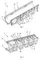
- the Fig. 1 and 2 show an isometric view of an embodiment of the drainage channel according to the invention 1.
- the drainage channel 1 comprises side walls 6, which are here partially formed as a channel body and the discharge of rainwater serve, which can enter via an upper portion 5 in the drainage channel 1.
- bearing surfaces 10 are provided, which serve to receive a cover and in particular a grate (not shown).
- the drainage channel 1 has a bottom surface 4, which closes the drainage channel downwards and moreover bearing surfaces for the positioning of the drainage channel 1 on a support bed and in particular a concrete surface (see Fig. 5-8 ) offers.
- support structures 8 which serve to dissipate forces that are registered on the cover (not shown) in the bearing surfaces 10 and further into the drainage channel 1.
- the support structures 8 are here designed as half-hexagonal support structures and in particular trapezoidal support structures. According to the invention they have approximately at mid-height of the drainage channel 1 base sections 12 whose function explicitly in the Fig. 5-8 is shown.
- the present invention designed as a hollow body support structures 8 and base sections 12 are formed open at the bottom, so that after relining or pouring the drainage channel 1 with concrete or other casting or relining material this material penetrates into the open hollow body and so both a vertical also allows a horizontal fixation of the drainage channel 1.
- the support structures 8 formed as a hollow body runs downwards to the bottom surface 4. This facilitates u.a. the penetration of concrete during relining or pouring.
- the base sections 12 have bearing ribs 22 up to a free edge 14 which are formed substantially parallel to the bottom surface 4. They allow not only the effective vertical load input but also a fixation of the channel against lifting of the forces.
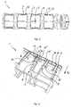
- Fig. 1 The embodiment of Fig. 1 is in Fig. 3 shown in a view of the bottom 3.
- the bottom surface 4 is shown, which merges into side walls 6.
- the support structures 8 project from the side walls 6 and essentially determine the outer contour of the channel 1.
- the support structures 8 have the base sections 12, which are here designed as honeycomb-shaped and downwards, ie in the direction of the bottom surface 4 open hollow body.
- Fig. 4 is the embodiment of Fig. 1 now shown in detail in an isometric view from diagonally below. It can be seen that the here honeycomb-shaped support structures 8, or formed in the upper portion base portions 12, trapezoidal surfaces, wherein two symmetrical trapezoidal surfaces 24 and a narrow side 28 is formed. The outer edges 26 of the symmetrical surfaces 24 are pulled through from the bottom 3 upwards 5, so that they determine the outer dimensions of the channel 1. In contrast, the narrow side 28 is inclined to the vertical (R v ), which prevents buckling of the trapezoidal support structure.
- the bearing surface 10 is also shown here, which in this embodiment flange portions 20 which extend between the individual support portions 8 and base portions 12.
- the flange portions also protrude outwardly from the side wall 6 so that they (as in Fig. 8 ) serve at a sufficient relining to the flange portions 20 of the derivative of forces.
- the aforementioned, inclined to the inside narrow sides 28 of the trapezoidal surfaces are arranged in this embodiment, that they are guided under the flange portions 20 and thus experience an optimal application of force.
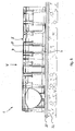
- Fig. 5 is now a side view of the embodiment Fig. 1 shown, wherein the embodiment is installed here as a class A-gutter.
- the channel 1 is founded on an in-situ concrete bed 30 which is laid out on a ground 32.
- the forces F, shown here as a point load F, which are introduced into the channel 1 via the upper side 5 of the channel 1 and in particular the bearing surfaces 10, can thus be easily transmitted via the support structures 8 to the bottom surface 4 and from there into the substrate 30, 32 be derived.
- Fig. 6 is now the embodiment of Fig. 1 represented in their installation form as class B gutter.
- an in-situ concrete layer 30 has been applied to the ground 32, which is here, however, brought up to a free edge 14 of the base sections 12 of the support structures 8.
- the base sections 12 thus rest with the bearing surfaces 22 formed on the free edge 14 on the in-situ concrete layer 30, so that forces which are introduced into the channel 1 via the upper edge 5, both via the support structures 12 and the bottom surface 4 in the underground are derivable.
- the load capacity of one and the same channel is significantly increased.
- the bearing ribs 22 are supported on the free edges 14 of the base sections 12 on the in-situ concrete layer 32 and thus ensure effective load transfer.
- the in-situ concrete layer 30 is slightly increased, so that the in-situ concrete penetrates into the hollow body formed as base portions 12, one achieves not only an improved load dissipation in the vertical direction R v , but also a fixation of the drainage channel 1 in the horizontal direction R H , here schematically as orthogonal Arrow to the vertical direction is shown.
- the in-situ concrete 32 here has been filled so that it just covers the bearing surfaces 22 of the base sections 12 and in the particular in Fig. 3 shown interior spaces of the base sections 12 penetrates. This leads, in addition to the fixation in the horizontal direction R 11 , to a reduction in the risk of buckling, since the bending of the walls 16 of the base sections 12 significantly reduces their buckling number.
- FIG. 8 Now the embodiment according to the invention of the drainage channel 1 is shown as a class C-channel.
- the in-situ concrete layer 30 is guided essentially to the upper edge 5 of the drainage channel 1. More precisely, it is here brought up to the flange portions 20 of the bearing surfaces 10, which, as in the Fig. 4 shown in detail, jump out of the outside of the drainage channel 1. Due to the relining of the flange portions 20, loads that are entered via the bearing surfaces 10 in the drainage channel 1, can now be derived in the upper region of the channel in the underground.
- the Fig. 8 shown mounting form thus guarantees the dissipation of very high loads, as a derivative of the flange 20, the base sections 12 and the bottom surface 4 can be made equally.
Landscapes
- Health & Medical Sciences (AREA)
- Life Sciences & Earth Sciences (AREA)
- Engineering & Computer Science (AREA)
- Hydrology & Water Resources (AREA)
- Public Health (AREA)
- Water Supply & Treatment (AREA)
- Sewage (AREA)
- External Artificial Organs (AREA)
- Liquid Developers In Electrophotography (AREA)
- Acyclic And Carbocyclic Compounds In Medicinal Compositions (AREA)
Description
- Vorliegende Erfindung betrifft eine Entwässerungsrinne, einen Straßenablauf oder eine ähnliche in einen Böden einbaubare Entwässerungsrinne, mit einer Bodenfläche und Seitenwänden, die nach außen hervorspringende Stützstrukturen aufweisen, welche Auflagerflächen zum Auflegen einer Abdeckung, insbesondere eines Rostes in einer Vertikalrichtung abstützen.
- Unter Entwässerungsrinne, Straßenablauf oder ähnliche in einen Boden einbaubare Entwässerungseinrichtungen sind hier sämtliche Einrichtungen zu verstehen, die der Abführung von Oberflächenwasser oder ähnlichem Wasser, beispielsweise Niederschlagswasser, dienen. Meist sind diese Einrichtungen so verbaut, dass von einer angrenzenden Verkehrsfläche Wasser über eine Abdeckung in die Entwässerungseinrichtung eindringt und von dort über ein Rinnensystem oder ein Fallrohr abgeleitet wird. In diesem Zusammenhang sind hier also sowohl Rinnen als auch Straßenabläufe, Einläufe und ähnliche Einrichtungen, in jeder möglichen Form und Ausgestaltung, unter den obigen Begriffen und insbesondere unter dem Begriff Entwässerungsrinne subsumiert.
- Obige Entwässerungsrinnen sind aus dem Stand der Technik bekannt, wobei die genannten, nach außen hervorspringenden Stützstrukturen u.a. dem Abstützen der Auflagerflächen für die Abdeckung dienen. Insbesondere bei in Verkehrsflächen verbauten Entwässerungsrinnen ist es hier bisweilen nötig, sehr hohe Kräfte von den Auflagerflächen in den Untergrund abzuleiten. Die abzutragenden Belastungen hängen hier natürlich von der Verwendung der jeweiligen Rinne ab. So muss eine Rinne, die in nicht befahrenen Bereichen verwendet wird, sehr viel geringere Lasten abtragen als eine Rinne, die beispielsweise zur Entwässerung von Straßenbrücken gedacht ist. Diesen Lastunterschieden wird derzeit durch die Verwendung unterschiedlich dimensionierter Rinnen Rechnung getragen, die in drei Klassen eingeteilt werden können.
- So gilt Klasse A für eine Rinne, die auf einem flachen Betonbett verbaut wird und lediglich eine Belastung von 15 kN ableiten muss. In den Klassen B und C verwendet man Rinnen, die für sehr viel höhere Belastungen ausgelegt sind. So kann eine Rinne der Klasse B bis zu 125 kN und eine Rinne der Klasse C bis zu 250 kN in den Untergrund abtragen, ohne dass es zu deren Beschädigungen kommt. Hier werden gemäß dem Stand der Technik meist konstruktive Maßnahmen an den Rinnen, wie beispielsweise eine Erhöhung der Stützstrukturzahlen, eine Verstärkung der Rinnenwandungen oder eine Veränderung der Materialeigenschaften vorgenommen, um den hohen Lastanforderungen gerecht zu werden.
- Durch die Verwendung unterschiedlicher Rinnen für die verschiedenen Lastanforderungen, kommt es jedoch sowohl in der Produktion als auch im Vertrieb zu hohen Kosten, die es, wenn möglich, einzusparen gilt. Darüber hinaus hat sich gezeigt, dass die derzeit auf dem Markt erhältlichen Rinnensysteme, die insbesondere für die Klassen B und C nötigen hohen Lastzahlen lediglich durch sehr aufwändige und insbesondere materialintensive Konstruktionen erreichen. Beschädigungen an den verwendeten Rinnen sind hier sehr häufig aufzufinden.
- Dokument
JP-A-1 0088650 - Vorliegender Erfindung liegt folglich die Aufgabe zu Grunde, eine Entwässerungsrinne der eingangs genannten Art derart darzubieten, dass sie sowohl eine vielseitige und kostengünstige Verwendung und Herstellung, als auch eine dauerhafte Betriebszeit gewährleistet.
- Diese Aufgabe wird durch eine Entwässerungsrinne gemäss Anspruch 1 gelöst.
- Kern der Erfindung ist es also, dass ein und dieselbe Entwässerungsrinne durch die Ausbildung der oben genannten Stützstrukturen und in Abhängigkeit des Eingießens und/oder des Unterfütterns mit Beton unterschiedliche Laststufen erreichen kann. In diesem Zusammenhang sei erwähnt, dass die oben genannte Rinne natürlich nicht nur im Zusammenhang mit Ortbeton, sondern auch mit allen anderen aus dem Stand der Technik bekannten Materialien zum Einbau von Entwässerungsrinnen oder ähnlichen Entwässerungseinrichtungen verwendet werden kann und auch dort ihre erfindungsgemäßen Vorteile aufweist.
- Das allgemeine Erfindungsprinzip liegt also darin, dass die Stützstrukturen derart ausgebildet sind, dass je nach Einbau (Anfüllen von Beton) verschiedene Belastungsklassen entstehen, wobei eine sprungförmige Steigerung bei Erreichen der Sockelabschnitte durch das Eingießen gewährleistet ist.
- Durch die Ausbildung der nach außen hervorspringenden Stützstrukturen derart, dass sie Sockelabschnitte aufweisen, die höher liegen als die Bodenfläche, ist es möglich, obige Rinne in Abhängigkeit des Eingießens bzw. Unterfütterns mit Ortbeton oder einem statt dessen verwendeten Einbaumaterial, an mehrere, unterschiedliche Lastanforderungen zu adaptieren. Wird die erfindungsgemäße Rinne lediglich auf ein Betonbett gestellt, werden Lasten, die über die Abdeckung in die Rinne eingetragen werden, über die Stützstrukturen zur Bodenfläche und von dort in den Untergrund abgeleitet. Wird statt dessen die Rinne bis zu den Sockelabschnitten vergossen oder unterfüttert, können Lasten sowohl über die Sockelabschnitte als auch über die Bodenfläche in den Untergrund abgeleitet werden. Dies führt zu einer erheblich verbesserten Lastableitung. Wird also beispielsweise die Rinne in Klasse C eingebaut, so entsteht durch das Eingießen der Sockelabschnitte mit Beton ein zusätzlicher fester Halt für die entsprechende Stützstruktur, so dass plötzlich sehr viel höhere Belastungen ableitbar sind. Dieser Halt resultiert u.a. zum einen in vergrößerten Auflagerbereichen, zum anderen aber auch, wie im folgenden noch genauer erläutert werden wird, in einer reduzierten Knickgefahr.
- Ein und dieselbe Rinne kann so also in Abhängigkeit der Anzahl der verwendeten Sockelabschnitte an unterschiedliche Laststufen adaptiert werden. Natürlich ist es möglich, nicht nur einen Sockelabschnitt an der Stützstruktur auszubilden, sondern mehrere, insbesondere in unterschiedlichen Höhen angeordnete Sockelabschnitte, so dass unterschiedliche Lastklassen erzielbar sind.
- Erfindungsgemäß sind die Sockelabschnitte derart nach unten offen ausgebildet, dass deren Wände nach dem Unterfüttern oder Eingießen in Horizontalrichtung fixiert sind. Diese Horizontalfixierung erhöht in entscheidendem Maße die Lastableitfähigkeit der obigen Entwässerungsrinne. Darüber hinaus dient jedoch der nach unten offene Querschnitt auch der Verbesserung einer Vertikallastabtragung, da durch das Eindringen des eingegossenen oder unterfütterten Ortbetons in die nach unten offenen Sockelabschnitte die zulässige Druckspannung deutlich reduziert wird. Der Ortbeton dringt in den nach unten offenen Sockelabschnitt ein und verstärkt diesen, reduziert u.a die Knicklänge, so dass auch bei sehr hohen Lastzahlen eine Ausknicken bzw. -beulen der Sockelabschnitte verhindert wird.
- Erfindungsgemäß sind die Sockelabschnitte, mindestens abschnittsweise als sich in Vertikalrichtung erstreckende Hohlkörper mit durchgenenden Wänden zur Bildung eines Kastenquerschnittes ausgebildet, wobei die Hohlkörpen insbesondere einen trapezförmigen Querschnitt aufweisen. Dieser trapezförmige Querschnitt ist insbesondere bei der auf der Baustelle zu erwartenden vertikalen und horizontalen Lasteinleitung äußerst vorteilhaft. Darüber hinaus garantiert er eine sehr effektive Verzahnung mit dem eingegossenen bzw. unterfütternden Ortbeton. Neben dieser "halben hexagonalen Form" sind jedoch auch andere Querschnitte, wie beispielsweise Halbrundquerschnitte oder Vieleckquerschnitte realisierbar.
- Die erfindungsgemäße Ausbildung dieser, insbesondere wabenförmigen bzw. halbhexagonalförmigen Sockelabschnitte garantiert also die Ausbildung einer multifunktionalen Entwässerüngsrinne, bei geringem Materialbedarf und sehr hoher Lastableitfähigkeit.
- Erfindungsgemäß ist die Hälfte eines unteren Rands der Sockelabschnitte bis zur Bondenfläche verlaufend ausgebildet.
- Das bedeutet, dass der untere Rand der Hohlkörper in die Bodenfläche bzw. in die Füße der Rinne so übergeht, dass sie, insbesondere bei Verwendung in Klasse A, über diese Füße abgestützt werden kann. Beim Eingießen der Rinne in Ortbeton kann dann dieser erfindungsgemäß ausgebildete Hohlkörper sehr einfach mit Ortbeton gefüllt bzw. in diesen eingegossen werden.
- Vorzugsweise sind die als Hohlkörper ausgebildeten Stützstrukturen als im Querschnitt trapezförmige Hohlkörper ausgebildet, wobei symmetrische Flächen des trapezförmigen Hohlkörpers mit Außenkanten von unten nach oben bis an die Auflagerabschnitte durchgezogen sind, so dass sie die Außenmaße der Rinne bestimmen. Auf diese Weise werden sowohl Kräfte von den Auflagerabschnitten in den Untergrund abgeleitet, als auch eine Torsionssteifigkeit der Rinne gewährleistet, da die die Außenmaße bestimmenden symmetrischen Flächen des trapezförmigen Hohlkörpers Torsionskräfte effektiv aufnehmen.
- Vorzugsweise verläuft eine Schmalseite des trapezförmigen Hohlkörpers zur Vertikalen nach innen geneigt von unten nach oben. Da bei obigem Hohlkörper die zum Rinneninnenraum weisende Schmalseite des Trapezes meist vom Rinnenkörper selber gebildet wird, trifft diese Spezifizierung meist auf die nach außen weisende Schmalseite des trapezförmigen Hohlkörpers zu. Sie garantiert, dass es bei sehr hohen Lasten, die über die Abdeckung der Rinne in den Untergrund abgeleitet werden, nicht zum Ausbeulen des Hohlkörpers kommt. Darüber hinaus wird in Kombination mit der oben erwähnten erfindungsgemäßen Ausbildung der symmetrischen Flächen des trapezförmigen Hohlkörpers derart, dass sie die Außenmaße der Rinne bestimmen, eine Stützstruktur mit Hinterschneidungen gebildet, die die Entwässerungsrinne nach dem Vergießen bzw. Unterfüttern insbesondere in Horizontalrichtung fixiert. Eine verbesserte Lastableitung der Sockelabschnitte bzw. der Hohlkörper wird auch dadurch erreicht, dass die Hohlkörper vorzugsweise als nach oben konisch verjüngte Hohlkörper ausgebildet sind. Vorzugsweise weisen die Auflagerflächen zum Auflegen der Abdeckung Flanschabschnitte auf, die höher angeordnet sind als die Sockelabschnitte und die derart ausgebildet sind, dass nach Hinterfüttern mit und/oder Eingießen in Ortbeton diese Flanschabschnitte zusätzliche Abstützungen der Auflagerflächen bilden. Auf diese Weise ist es möglich, die Rinne beim Eingießen bis auf Höhe der Flanschabschnitte bis an eine Maximalbelastungsklasse heran zu führen. Erfindungsgemäß können dann Lasten sowohl über die Flanschabschnitte als auch über die Sockelabschnitte und die Bodenfläche der Rinne in den Untergrund abgeleitet werden.
- Vorzugsweise weisen die Stützstrukturen horizontale, im Wesentlichen parallel zu der Bodenfläche verlaufende Lagerrippen auf. Diese Lagerrippen können am unteren Rand der Stützstrukturen, oder aber frei positioniert zwischen ihrem jeweiligen oberen Rand und dem unteren Rand angeordnet sein und erlauben eine effektive Lastableitung in den Untergrund. Vorzugsweise sind sie wenigstens an einem freien Rand der Sockelabschnitte ausgebildet.
- Erfindungsgemäß ist auch eine Entwässerungsanordnung mit einer erfindungsgemässen Entwasserungsrinne und ein Verfahren zun Einbau einer erfindungsgemässen Entwässerungsrinne vorgesehen.
- Weitere Ausführungsformen der Erfindung ergeben sich aus den Unteransprüchen.
- Im Folgenden wird die Erfindung anhand eines Ausführungsbeispiels beschrieben, das durch die beiliegenden Zeichnungen näher erläutert wird. Hierbei zeigt:
-
Fig. 1 eine isometrische Darstellung einer Ausführungsform der Entwässerungsrinne von schräg oben; -
Fig. 2 eine isometrische Darstellung der Ausführungsform ausFig. 1 von schräg unten; -
Fig. 3 eine Unteransicht der Ausführungsform ausFig. 1 ; -
Fig. 4 eine isometrische Detailansicht der Ausführungsform ausFig. 1 von schräg unten; -
Fig. 5 eine Seitenansicht der Ausführungsform ausFig. 1 im Einbauzustand als Klasse A-Rinne; -
Fig. 6 eine Seitenansicht der Ausführungsform ausFig. 1 im Einbauzustand als Klasse B-Rinne; -
Fig. 7 eine Seitenansicht der Ausführungsform ausFig. 1 im Einbauzustand als Klasse B-Rinne mit verbesserter Horizontalfixierung; und -
Fig. 8 eine Seitenansicht der Ausführungsform ausFig. 1 im Einbauzustand als Klasse C-Rinne. - Im Folgenden werden für gleiche und gleich wirkende Bauteile dieselben Bezugsziffern verwendet.
- Die
Fig. 1 und 2 zeigen eine isometrische Darstellung einer Ausführungsform der erfindungsgemäßen Entwässerungsrinne 1. Die Entwässerungsrinne 1 umfasst Seitenwände 6, die hier teilweise als Rinnenkörper geformt sind und der Ableitung von Niederschlagswasser dienen, das über einen oberen Bereich 5 in die Entwässerungsrinne 1 eintreten kann. Am oberen Bereich 5 sind Auflagerflächen 10 vorgesehen, die der Aufnahme einer Abdeckung und insbesondere eines Rostes (nicht dargestellt) dienen. Am unteren Bereich 3 weist die Entwässerungsrinne 1 eine Bodenfläche 4 auf, die die Entwässerungsrinne nach unten abschließt und darüber hinaus Lagerflächen für die Positionierung der Entwässerungsrinne 1 auf einem Stützbett und insbesondere einer Betonfläche (sieheFig. 5-8 ) bietet. Am unteren Bereich 3 bzw. der Bodenfläche 4 bis zum oberen Bereich 5 der Rinne 1 verlaufen Stützstrukturen 8, die der Ableitung von Kräften dienen, die über die Abdeckung (nicht dargestellt) in die Auflagerflächen 10 und weiter in die Entwässerungsrinne 1 eingetragen werden. - Die Stützstrukturen 8 sind hier als halbhexagonale Stützstrukturen und insbesondere trapezförmige Stützstrukturen ausgebildet. Erfindungsgemäß weisen sie in etwa auf mittlerer Höhe der Entwässerungsrinne 1 Sockelabschnitte 12 auf, deren Funktion explizit in den
Fig. 5 - 8 dargestellt ist. - Die erfindungsgemäß hier als Hohlkörper ausgebildeten Stützstrukturen 8 bzw. Sockelabschnitte 12 sind nach unten offen ausgebildet, so dass nach dem Unterfüttern oder Eingießen der Entwässerungsrinne 1 mit Beton oder einem anderen Guss- oder Unterfütterungsmaterial dieses Material in die offenen Hohlkörper eindringt und so sowohl eine vertikale als auch eine horizontale Fixierung der Entwässerungsrinne 1 ermöglicht. Dazu verläuft hier wenigstens ein Teil eines unteren Randes 18, der als Hohlkörper ausgebildeten Stützstrukturen 8 nach unten 3 bis zur Bodenfläche 4. Dies erleichtert u.a. das Eindringen von Beton beim Unterfüttern bzw. Eingießen.
- Um die Kraftableitung in den eingegossenen oder unterfütternden Ortbeton bzw. das entsprechend verwendete Material zu verbessern, weisen die Sockelabschnitte 12 hier bis an einem freien Rand 14 Lagerrippen 22 auf, die im Wesentlichen parallel zur Bodenfläche 4 ausgebildet sind. Sie erlauben neben der effektiven Vertikallasteinleitung auch eine Fixierung der Rinne gegen Abheben der Kräfte.
- Die Ausführungsform aus
Fig. 1 ist inFig. 3 in einer Ansicht der Unterseite 3 dargestellt. Hier ist die Bodenfläche 4 gezeigt, die in Seitenwände 6 übergeht. Erkennbar ist, dass die Stützstrukturen 8 aus den Seitenwänden 6 hervorspringen und im Wesentlichen die Außenkontur der Rinne 1 bestimmen. Die Stützstrukturen 8 weisen die Sockelabschnitte 12 auf, die hier als wabenförmige und nach unten, also in Richtung der Bodenfläche 4 offene Hohlkörper ausgebildet sind. - In
Fig. 4 ist die Ausführungsform ausFig. 1 nun detailliert in einer isometrischen Darstellung von schräg unten dargestellt. Erkennbar ist, dass die hier wabenförmig ausgebildeten Stützstrukturen 8, bzw. die im oberen Bereich ausgebildeten Sockelabschnitte 12, Trapezflächen aufweisen, wobei zwei symmetrische Trapezflächen 24 und eine Schmalseite 28 ausgebildet ist. Die Außenkanten 26 der symmetrischen Flächen 24 sind dabei von unten 3 nach oben 5 durchgezogen, so dass sie die Außenmaße der Rinne 1 bestimmen. Im Gegensatz dazu verläuft die Schmalseite 28 zur Vertikalen (Rv) geneigt, was ein Ausbeulen der trapezförmigen Stützstruktur verhindert. - Am Oberrand 5 ist hier ebenfalls die Auflagerfläche 10 dargestellt, die bei dieser Ausführungsform Flanschabschnitte 20 aufweist, die sich zwischen den einzelnen Stützabschnitten 8 bzw. Sockelabschnitten 12 erstrecken. Die Flanschabschnitte stehen hier ebenfalls nach außen aus der Seitenwand 6 hervor, so dass sie (wie in
Fig. 8 ) bei einer ausreichenden Unterfütterung bis an die Flanschabschnitte 20 der Ableitung von Kräften dienen. Die zuvor erwähnten, zur Innenseite geneigten Schmalseiten 28 der Trapezflächen sind bei dieser Ausführungsform so angeordnet, dass sie unter die Flanschabschnitte 20 geführt sind und so eine optimale Krafteinleitung erfahren. - In
Fig. 5 ist nun eine Seitenansicht der Ausführungsform ausFig. 1 dargestellt, wobei die Ausführungsform hier als Klasse A-Rinne verbaut wird. Dazu wird die Rinne 1 auf ein Ortbetonbett 30 gegründet, das auf einem Erdboden 32 ausgebracht ist. Die Kräfte F, hier als ein Punktlast F dargestellt, die über die Oberseite 5 der Rinne 1 und insbesondere die Auflagerflächen 10 in die Rinne 1 eingetragen werden, können so über die Stützstrukturen 8 einfach zur Bodenfläche 4 und von dort in den Untergrund 30;32 abgeleitet werden. - In
Fig. 6 ist nun die Ausführungsform ausFig. 1 in ihrer Einbauform als Klasse B-Rinne dargestellt. Dazu ist ebenfalls wieder eine Ortbetonschicht 30 auf den Erdboden 32 aufgebracht worden, die hier jedoch bis an einen freien Rand 14 der Sockelabschnitte 12 der Stützstrukturen 8 herangeführt ist. Die Sockelabschnitte 12 liegen also mit den am freien Rand 14 ausgebildeten Lagerflächen 22 auf der Ortbetonschicht 30 auf, so dass Kräfte, die über den oberen Rand 5 in die Rinne 1 eingeleitet werden, sowohl über die Stützstrukturen 12 als auch die Bodenfläche 4 in den Untergrund ableitbar sind. Auf diese Weise wird die Lastfähigkeit ein und derselben Rinne entscheidend erhöht. Dargestellt ist weiter, dass die Lagerrippen 22 an den freien Rändern 14 der Sockelabschnitte 12 auf der Ortbetonschicht 32 aufgelagert sind und so eine effektive Lasteinleitung gewährleisten. - Wird nun, wie in
Fig. 7 dargestellt, die Ortbetonschicht 30 geringfügig erhöht, so dass der Ortbeton in die als Hohlkörper ausgebildeten Sockelabschnitte 12 eindringt, erzielt man nicht nur eine verbesserte Lastableitung in Vertikalrichtung Rv, sondern auch eine Fixierung der Entwässerungsrinne 1 in Horizontalrichtung RH, die hier schematisch als orthogonaler Pfeil zur Vertikalrichtung dargestellt ist. Deutlich ist, dass der Ortbeton 32 hier so angefüllt wurde, dass er die Lagerflächen 22 der Sockelabschnitte 12 gerade überdeckt und in die insbesondere inFig. 3 dargestellten Innenräume der Sockelabschnitte 12 eindringt. Dies führt neben der Fixierung in Horizontalrichtung R11 auch zur einer Reduzierung der Knickgefahr, da sich durch das Aussteifen der Wände 16 der Sockelanschnitte 12 deren Knickzahl deutlich reduziert. - In
Fig. 8 ist nun die erfindungsgemäße Ausführungsform der Entwässerungsrinne 1 als eine Klasse C-Rinne dargestellt. Die Ortbetonschicht 30 ist im Wesentlichen bis zum Oberrand 5 der Entwässerungsrinne 1 geführt. Genauer gesagt, ist sie hier bis an die Flanschabschnitte 20 der Auflagerflächen 10 herangeführt, die, wie in derFig. 4 im Detail dargestellt, aus der Außenseite der Entwässerungsrinne 1 hervorspringen. Durch die Unterfütterung der Flanschabschnitte 20 können Lasten, die über die Auflagerflächen 10 in die Entwässerungsrinne 1 eingetragen werden, nun bereits im oberen Bereich der Rinne in den Untergrund abgeleitet werden. Die inFig. 8 dargestellte Einbauform garantiert also die Ableitung sehr hoher Lasten, da eine Ableitung über die Flanschabschnitte 20, die Sockelabschnitte 12 und die Bodenfläche 4 gleichermaßen erfolgen kann. -
- 1
- Entwässerungsrinne
- 3
- Unterer Bereich
- 4
- Bodenfläche
- 5
- Oberer Bereich
- 6
- Seitenwände
- 8
- Stützstrukturen
- 10
- Auflagerflächen
- 12
- Sockelabschnitt
- 14
- Freier Rand
- 16
- Wände der Sockelabschnitte
- 18
- Unterer Rand
- 20
- Flanschabschnitte
- 22
- Lagerrippe
- 24
- Symmetrische Flächen
- 26
- Außenkanten
- 28
- Schmalseite
- 30
- Ortbeton
- 32
- Erdboden
- Rv
- Vertikalrichtung
- RH
- Horizontalrichtung
Claims (10)
- Entwässerungsrinne, Straßenablauf oder ähnliche in einen Boden einbaubare Entwässerungseinrichtung, mit einer Bodenfläche (4) und Seitenwänden (6), die nach außen hervorspringende Stützstrukturen (8) aufweisen, die Auflagerflächen (10) zum Auflegen einer Abdeckung, insbesondere eines Rostes, in einer Vertikalrichtung Rv abstützen, wobei mindestens Gruppen der Stützstrukturen (8) Sockelabschnitte (12) aufweisen, die höher und somit näher an den Auflagerflächen (10) angeordnet sind als die Bodenflächen (4) und die derart ausgebildet sind, dass nach Unterfüttern mit und/oder Eingießen in Ortbeton (30) diese Sockelabschnitte (12) zusätzliche Abstützungen der Auflagerflächen (10) bilden, wobei die Sockelabschnitte (12) in Vertikalrichtung Rv gesehen, mindestens abschnittsweise als Hohlkörper mit durchgehenden Wänden (16) zur Bildung eines Kastenquerschnittes ausgebildet und derart nach unten offen sind, dass die Wände (16) nach dem Unterfüttern oder Eingießen in Horizontalrichtung RH fixiert sind,
dadurch gekennzeichnet, dass
die Hälfte eines unteren Rands (18) der Sockelabschnitte (12) bis zur Bodenfläche (4) verlaufend ausgebildet ist. - Entwässerungsrinne nach Anspruch 1,
dadurch gekennzeichnet, dass
die Sockelabschnitte (12) als sich in Vertikalrichtung Rv erstreckende Hohlkörper ausgebildet sind, die einen trapezförmigen Querschnitt aufweisen. - Entwässerungsrinne nach einem der vorhergehenden Ansprüche,
dadurch gekennzeichnet, dass
symmetrische Flächen (24) der trapezförmigen Hohlkörper mit Außenkanten (26) von unten (3) nach oben (5) an die Flanschabschnitte (20) durchgezogen sind, so dass sie die Außenmaße der Rinne (1) bestimmen. - Entwässerungsrinne nach einem der vorhergehenden Ansprüche,
dadurch gekennzeichnet, dass
eine Schmalseite (28) der trapezförmigen Hohlkörper zur Vertikalen nach innen geneigt, von unten (3) nach oben (5) verläuft. - Entwässerungsrinne nach einem der vorhergehenden Ansprüche,
dadurch gekennzeichnet, dass
die Hohlkörper als nach oben (5) konisch verjüngte Hohlkörper ausgebildet sind. - Entwässerungsrinne nach einem der vorhergehenden Ansprüche,
dadurch gekennzeichnet, dass
die Auflagerflächen (10) zum Auflegen der Abdeckung Flanschabschnitte (20) aufweisen, die höher angeordnet sind, als die Sockelabschnitte (12) und die derart ausgebildet sind, dass nach Unterfüttern mit und/oder Eingießen in Ortbeton diese Flanschabschnitte (20) zusätzliche Abstützungen der Auflagerflächen (10) bilden. - Entwässerungsrinne nach einem der vorhergehenden Ansprüche,
dadurch gekennzeichnet, dass
die Stützstrukturen (8) horizontale, im Wesentlichen parallel zu der Bodenfläche (4) verlaufende Lagerrippen (22) aufweisen. - Entwässerungsrinne nach einem der vorhergehenden Ansprüche,
dadurch gekennzeichnet, dass
die Lagerrippen (22) wenigstens an einem freien Rand (14) der Sockelabschnitte (12) ausgebildet sind. - Entwässerungsrinnenanordnung mit einer Entwässerungsrinne nach einem der vorhergehenden Ansprüche,
wobei die Entwässerungsrinne derart in einen Erdboden (32) eingebaut ist, dass die Stützstrukturen (8) mit Ortbeton (30) unterfüttert sind. - Verfahren zum Einbau einer Entwässerungsrinne nach einem der Ansprüche 1 bis 8,
wobei die Entwässerungsrinne zur Erzielung- einer geringen Laststufe lediglich auf ein Betonbett gestellt wird,- einer mittleren Laststufe bis zu den Sockelabschnitten vergossen oder unterfüttert wird, und- einer höchsten Laststufe bis zu einem Oberrand (5) vergossen wird.
Priority Applications (3)
| Application Number | Priority Date | Filing Date | Title |
|---|---|---|---|
| PL08785309T PL2188459T3 (pl) | 2007-08-17 | 2008-08-01 | Rynna odwadniająca |
| HRP20161651TT HRP20161651T1 (hr) | 2007-08-17 | 2008-08-01 | Odvodni kanal |
| SI200831694A SI2188459T1 (sl) | 2007-08-17 | 2008-08-01 | Žleb za odvodnjavanje |
Applications Claiming Priority (2)
| Application Number | Priority Date | Filing Date | Title |
|---|---|---|---|
| DE102007038968A DE102007038968B3 (de) | 2007-08-17 | 2007-08-17 | Entwässerungsrinne |
| PCT/EP2008/006375 WO2009024255A1 (de) | 2007-08-17 | 2008-08-01 | Entwässerungsrinne |
Publications (2)
| Publication Number | Publication Date |
|---|---|
| EP2188459A1 EP2188459A1 (de) | 2010-05-26 |
| EP2188459B1 true EP2188459B1 (de) | 2016-10-12 |
Family
ID=39884814
Family Applications (1)
| Application Number | Title | Priority Date | Filing Date |
|---|---|---|---|
| EP08785309.9A Active EP2188459B1 (de) | 2007-08-17 | 2008-08-01 | Entwässerungsrinne |
Country Status (9)
| Country | Link |
|---|---|
| EP (1) | EP2188459B1 (de) |
| DE (1) | DE102007038968B3 (de) |
| DK (1) | DK2188459T3 (de) |
| HR (1) | HRP20161651T1 (de) |
| HU (1) | HUE032143T2 (de) |
| LT (1) | LT2188459T (de) |
| PL (1) | PL2188459T3 (de) |
| SI (1) | SI2188459T1 (de) |
| WO (1) | WO2009024255A1 (de) |
Families Citing this family (3)
| Publication number | Priority date | Publication date | Assignee | Title |
|---|---|---|---|---|
| RU2555978C1 (ru) * | 2014-06-23 | 2015-07-10 | Олег Романович Дутко | Водоотводной лоток из пластика |
| RU2557262C1 (ru) * | 2014-06-25 | 2015-07-20 | Олег Романович Дутко | Водоотводный лоток из пластика |
| EP4194629B1 (de) | 2021-12-08 | 2024-11-13 | Hauraton GmbH & Co. KG | Entwässerungsrinne mit einem aus kunststoff gefertigten rinnenkörper |
Family Cites Families (7)
| Publication number | Priority date | Publication date | Assignee | Title |
|---|---|---|---|---|
| JP3811530B2 (ja) * | 1996-09-18 | 2006-08-23 | 大和技研工業株式会社 | プラスチック製u形側溝 |
| DE19745480A1 (de) * | 1997-10-15 | 1999-04-22 | Bernhard Kessel | Entwässerungsrinne |
| DE10143985C1 (de) * | 2001-09-08 | 2003-01-30 | Funke Kunststoffe Gmbh | Rinnenabschnitt zur Herstellung einer Rinne zur Aufnahme von Oberflächenwasser |
| DE20307802U1 (de) * | 2003-05-20 | 2003-09-25 | Hauraton Betonwarenfabrik GmbH & Co. KG, 76437 Rastatt | Kunststoffrinne |
| FR2861758B1 (fr) * | 2003-10-31 | 2009-01-16 | Nicoll Raccords Plastiques | Element de caniveau |
| DE202005004634U1 (de) * | 2005-03-22 | 2005-06-09 | Hauraton Betonwarenfabrik Gmbh & Co Kg | Retentionsrinnenmodul |
| US7866911B2 (en) * | 2005-10-07 | 2011-01-11 | Zurn Industries, Llc | Slotted drain |
-
2007
- 2007-08-17 DE DE102007038968A patent/DE102007038968B3/de active Active
-
2008
- 2008-08-01 DK DK08785309.9T patent/DK2188459T3/en active
- 2008-08-01 LT LTEP08785309.9T patent/LT2188459T/lt unknown
- 2008-08-01 SI SI200831694A patent/SI2188459T1/sl unknown
- 2008-08-01 HU HUE08785309A patent/HUE032143T2/en unknown
- 2008-08-01 EP EP08785309.9A patent/EP2188459B1/de active Active
- 2008-08-01 WO PCT/EP2008/006375 patent/WO2009024255A1/de not_active Ceased
- 2008-08-01 PL PL08785309T patent/PL2188459T3/pl unknown
- 2008-08-01 HR HRP20161651TT patent/HRP20161651T1/hr unknown
Also Published As
| Publication number | Publication date |
|---|---|
| DK2188459T3 (en) | 2017-01-30 |
| LT2188459T (lt) | 2016-12-12 |
| PL2188459T3 (pl) | 2017-06-30 |
| DE102007038968B3 (de) | 2009-04-09 |
| EP2188459A1 (de) | 2010-05-26 |
| WO2009024255A1 (de) | 2009-02-26 |
| HRP20161651T1 (hr) | 2017-02-10 |
| HUE032143T2 (en) | 2017-08-28 |
| SI2188459T1 (sl) | 2017-01-31 |
Similar Documents
| Publication | Publication Date | Title |
|---|---|---|
| CH674231A5 (de) | ||
| EP2851477B1 (de) | Entwässerungsrinne | |
| WO2020169215A1 (de) | Entwässerungssystem, einheiten und verfahren | |
| DE102016101251A1 (de) | Oberflächenentwässerungseinrichtung | |
| EP2896746B1 (de) | Entwässerungssystem | |
| EP2188459B1 (de) | Entwässerungsrinne | |
| EP1757742A2 (de) | Rigolenelement mit Inspektionskanal | |
| DE102016114855A1 (de) | Trogförmiger Überbau für eine Brücke, Brücke, Betonfertigteil für eine Trogwange einer Brücke sowie Verfahren zur Herstellung einer Brücke | |
| EP3075908B1 (de) | Schlitzrinne | |
| DE102007051189B4 (de) | Ablaufeinrichtung | |
| DE102013104405A1 (de) | Entwässerungsrinnensystem | |
| DE102016205081A1 (de) | Übergangskonstruktion zur Überbrückung einer Bauwerksfuge | |
| EP3369862B1 (de) | Rinnenelement zur bildung einer entwässerungsrinne | |
| DE202008013316U1 (de) | Entwässerungssystem für Oberflächenwasser | |
| EP2505721B1 (de) | Straßenaufsatz | |
| DE10355089B3 (de) | Rohrbrücke | |
| AT520609A1 (de) | Entwässerungsvorrichtung zum Entwässern eines Untergrunds | |
| EP1234913A2 (de) | Entwässerungsrinne | |
| DE102010045454A1 (de) | Brückenüberbau mit externer Bewehrung | |
| DE10201346B4 (de) | Ablaufvorrichtung für einen Fliesenfußboden | |
| DE3426160C2 (de) | ||
| EP1736605A2 (de) | Balkonzarge, Balkon sowie Verfahren zum Herstellen eines Fertigteilbalkons | |
| DE202010014642U1 (de) | Anschluss eines in ein Straßenbauwerk eingesetzten Einbauteils | |
| DE102015110887A1 (de) | Vorrichtung und Verfahren zum Anheben einer Schachtabdeckung insbesondere Kanaldeckel | |
| DE29609852U1 (de) | Auflagervorrichtung für Abdeckungen von in Verkehrsflächen liegenden Schächten |
Legal Events
| Date | Code | Title | Description |
|---|---|---|---|
| PUAI | Public reference made under article 153(3) epc to a published international application that has entered the european phase |
Free format text: ORIGINAL CODE: 0009012 |
|
| 17P | Request for examination filed |
Effective date: 20100312 |
|
| AK | Designated contracting states |
Kind code of ref document: A1 Designated state(s): AT BE BG CH CY CZ DE DK EE ES FI FR GB GR HR HU IE IS IT LI LT LU LV MC MT NL NO PL PT RO SE SI SK TR |
|
| AX | Request for extension of the european patent |
Extension state: AL BA MK RS |
|
| DAX | Request for extension of the european patent (deleted) | ||
| 17Q | First examination report despatched |
Effective date: 20140131 |
|
| GRAP | Despatch of communication of intention to grant a patent |
Free format text: ORIGINAL CODE: EPIDOSNIGR1 |
|
| INTG | Intention to grant announced |
Effective date: 20160324 |
|
| GRAS | Grant fee paid |
Free format text: ORIGINAL CODE: EPIDOSNIGR3 |
|
| GRAA | (expected) grant |
Free format text: ORIGINAL CODE: 0009210 |
|
| AK | Designated contracting states |
Kind code of ref document: B1 Designated state(s): AT BE BG CH CY CZ DE DK EE ES FI FR GB GR HR HU IE IS IT LI LT LU LV MC MT NL NO PL PT RO SE SI SK TR |
|
| REG | Reference to a national code |
Ref country code: GB Ref legal event code: FG4D Free format text: NOT ENGLISH |
|
| REG | Reference to a national code |
Ref country code: CH Ref legal event code: EP |
|
| REG | Reference to a national code |
Ref country code: AT Ref legal event code: REF Ref document number: 836645 Country of ref document: AT Kind code of ref document: T Effective date: 20161015 |
|
| REG | Reference to a national code |
Ref country code: IE Ref legal event code: FG4D Free format text: LANGUAGE OF EP DOCUMENT: GERMAN |
|
| REG | Reference to a national code |
Ref country code: DE Ref legal event code: R096 Ref document number: 502008014713 Country of ref document: DE |
|
| REG | Reference to a national code |
Ref country code: HR Ref legal event code: TUEP Ref document number: P20161651 Country of ref document: HR |
|
| REG | Reference to a national code |
Ref country code: RO Ref legal event code: EPE |
|
| REG | Reference to a national code |
Ref country code: SE Ref legal event code: TRGR |
|
| REG | Reference to a national code |
Ref country code: DK Ref legal event code: T3 Effective date: 20170124 |
|
| REG | Reference to a national code |
Ref country code: HR Ref legal event code: T1PR Ref document number: P20161651 Country of ref document: HR |
|
| REG | Reference to a national code |
Ref country code: EE Ref legal event code: FG4A Ref document number: E013030 Country of ref document: EE Effective date: 20170102 Ref country code: NL Ref legal event code: MP Effective date: 20161012 |
|
| REG | Reference to a national code |
Ref country code: NO Ref legal event code: T2 Effective date: 20161012 |
|
| PG25 | Lapsed in a contracting state [announced via postgrant information from national office to epo] |
Ref country code: GR Free format text: LAPSE BECAUSE OF FAILURE TO SUBMIT A TRANSLATION OF THE DESCRIPTION OR TO PAY THE FEE WITHIN THE PRESCRIBED TIME-LIMIT Effective date: 20170113 |
|
| PG25 | Lapsed in a contracting state [announced via postgrant information from national office to epo] |
Ref country code: NL Free format text: LAPSE BECAUSE OF FAILURE TO SUBMIT A TRANSLATION OF THE DESCRIPTION OR TO PAY THE FEE WITHIN THE PRESCRIBED TIME-LIMIT Effective date: 20161012 Ref country code: ES Free format text: LAPSE BECAUSE OF FAILURE TO SUBMIT A TRANSLATION OF THE DESCRIPTION OR TO PAY THE FEE WITHIN THE PRESCRIBED TIME-LIMIT Effective date: 20161012 Ref country code: PT Free format text: LAPSE BECAUSE OF FAILURE TO SUBMIT A TRANSLATION OF THE DESCRIPTION OR TO PAY THE FEE WITHIN THE PRESCRIBED TIME-LIMIT Effective date: 20170213 Ref country code: IS Free format text: LAPSE BECAUSE OF FAILURE TO SUBMIT A TRANSLATION OF THE DESCRIPTION OR TO PAY THE FEE WITHIN THE PRESCRIBED TIME-LIMIT Effective date: 20170212 |
|
| REG | Reference to a national code |
Ref country code: SK Ref legal event code: T3 Ref document number: E 23195 Country of ref document: SK |
|
| REG | Reference to a national code |
Ref country code: DE Ref legal event code: R097 Ref document number: 502008014713 Country of ref document: DE |
|
| PLBE | No opposition filed within time limit |
Free format text: ORIGINAL CODE: 0009261 |
|
| STAA | Information on the status of an ep patent application or granted ep patent |
Free format text: STATUS: NO OPPOSITION FILED WITHIN TIME LIMIT |
|
| REG | Reference to a national code |
Ref country code: FR Ref legal event code: PLFP Year of fee payment: 10 |
|
| REG | Reference to a national code |
Ref country code: HU Ref legal event code: AG4A Ref document number: E032143 Country of ref document: HU |
|
| 26N | No opposition filed |
Effective date: 20170713 |
|
| REG | Reference to a national code |
Ref country code: CH Ref legal event code: PL |
|
| PG25 | Lapsed in a contracting state [announced via postgrant information from national office to epo] |
Ref country code: MC Free format text: LAPSE BECAUSE OF FAILURE TO SUBMIT A TRANSLATION OF THE DESCRIPTION OR TO PAY THE FEE WITHIN THE PRESCRIBED TIME-LIMIT Effective date: 20161012 |
|
| PG25 | Lapsed in a contracting state [announced via postgrant information from national office to epo] |
Ref country code: LI Free format text: LAPSE BECAUSE OF NON-PAYMENT OF DUE FEES Effective date: 20170831 Ref country code: CH Free format text: LAPSE BECAUSE OF NON-PAYMENT OF DUE FEES Effective date: 20170831 |
|
| REG | Reference to a national code |
Ref country code: IE Ref legal event code: MM4A |
|
| REG | Reference to a national code |
Ref country code: BE Ref legal event code: MM Effective date: 20170831 |
|
| PG25 | Lapsed in a contracting state [announced via postgrant information from national office to epo] |
Ref country code: LU Free format text: LAPSE BECAUSE OF NON-PAYMENT OF DUE FEES Effective date: 20170801 |
|
| PG25 | Lapsed in a contracting state [announced via postgrant information from national office to epo] |
Ref country code: IE Free format text: LAPSE BECAUSE OF NON-PAYMENT OF DUE FEES Effective date: 20170801 |
|
| REG | Reference to a national code |
Ref country code: FR Ref legal event code: PLFP Year of fee payment: 11 |
|
| PG25 | Lapsed in a contracting state [announced via postgrant information from national office to epo] |
Ref country code: BE Free format text: LAPSE BECAUSE OF NON-PAYMENT OF DUE FEES Effective date: 20170831 |
|
| PG25 | Lapsed in a contracting state [announced via postgrant information from national office to epo] |
Ref country code: MT Free format text: LAPSE BECAUSE OF FAILURE TO SUBMIT A TRANSLATION OF THE DESCRIPTION OR TO PAY THE FEE WITHIN THE PRESCRIBED TIME-LIMIT Effective date: 20161012 |
|
| REG | Reference to a national code |
Ref country code: HR Ref legal event code: ODRP Ref document number: P20161651 Country of ref document: HR Payment date: 20190724 Year of fee payment: 12 |
|
| PG25 | Lapsed in a contracting state [announced via postgrant information from national office to epo] |
Ref country code: CY Free format text: LAPSE BECAUSE OF NON-PAYMENT OF DUE FEES Effective date: 20161012 |
|
| PG25 | Lapsed in a contracting state [announced via postgrant information from national office to epo] |
Ref country code: TR Free format text: LAPSE BECAUSE OF FAILURE TO SUBMIT A TRANSLATION OF THE DESCRIPTION OR TO PAY THE FEE WITHIN THE PRESCRIBED TIME-LIMIT Effective date: 20161012 |
|
| REG | Reference to a national code |
Ref country code: HR Ref legal event code: ODRP Ref document number: P20161651 Country of ref document: HR Payment date: 20200728 Year of fee payment: 13 |
|
| REG | Reference to a national code |
Ref country code: EE Ref legal event code: HC1A Ref document number: E013030 Country of ref document: EE |
|
| REG | Reference to a national code |
Ref country code: HR Ref legal event code: ODRP Ref document number: P20161651 Country of ref document: HR Payment date: 20210722 Year of fee payment: 14 |
|
| PGFP | Annual fee paid to national office [announced via postgrant information from national office to epo] |
Ref country code: EE Payment date: 20210818 Year of fee payment: 14 Ref country code: LT Payment date: 20210722 Year of fee payment: 14 |
|
| PGFP | Annual fee paid to national office [announced via postgrant information from national office to epo] |
Ref country code: LV Payment date: 20210819 Year of fee payment: 14 Ref country code: SK Payment date: 20210722 Year of fee payment: 14 |
|
| REG | Reference to a national code |
Ref country code: HR Ref legal event code: ODRP Ref document number: P20161651 Country of ref document: HR Payment date: 20220726 Year of fee payment: 15 |
|
| PGFP | Annual fee paid to national office [announced via postgrant information from national office to epo] |
Ref country code: HU Payment date: 20220722 Year of fee payment: 15 |
|
| REG | Reference to a national code |
Ref country code: LT Ref legal event code: MM4D Effective date: 20220801 |
|
| REG | Reference to a national code |
Ref country code: EE Ref legal event code: MM4A Ref document number: E013030 Country of ref document: EE Effective date: 20220831 |
|
| REG | Reference to a national code |
Ref country code: SK Ref legal event code: MM4A Ref document number: E 23195 Country of ref document: SK Effective date: 20220801 |
|
| PG25 | Lapsed in a contracting state [announced via postgrant information from national office to epo] |
Ref country code: LT Free format text: LAPSE BECAUSE OF NON-PAYMENT OF DUE FEES Effective date: 20220801 |
|
| PG25 | Lapsed in a contracting state [announced via postgrant information from national office to epo] |
Ref country code: SK Free format text: LAPSE BECAUSE OF NON-PAYMENT OF DUE FEES Effective date: 20220801 Ref country code: LV Free format text: LAPSE BECAUSE OF NON-PAYMENT OF DUE FEES Effective date: 20220801 Ref country code: EE Free format text: LAPSE BECAUSE OF NON-PAYMENT OF DUE FEES Effective date: 20220831 |
|
| REG | Reference to a national code |
Ref country code: HR Ref legal event code: ODRP Ref document number: P20161651 Country of ref document: HR Payment date: 20230721 Year of fee payment: 16 |
|
| P01 | Opt-out of the competence of the unified patent court (upc) registered |
Effective date: 20230629 |
|
| PG25 | Lapsed in a contracting state [announced via postgrant information from national office to epo] |
Ref country code: HU Free format text: LAPSE BECAUSE OF NON-PAYMENT OF DUE FEES Effective date: 20230802 |
|
| REG | Reference to a national code |
Ref country code: HR Ref legal event code: ODRP Ref document number: P20161651 Country of ref document: HR Payment date: 20240729 Year of fee payment: 17 |
|
| REG | Reference to a national code |
Ref country code: HR Ref legal event code: ODRP Ref document number: P20161651 Country of ref document: HR Payment date: 20250718 Year of fee payment: 18 |
|
| PGFP | Annual fee paid to national office [announced via postgrant information from national office to epo] |
Ref country code: FI Payment date: 20250820 Year of fee payment: 18 |
|
| PGFP | Annual fee paid to national office [announced via postgrant information from national office to epo] |
Ref country code: DK Payment date: 20250821 Year of fee payment: 18 Ref country code: DE Payment date: 20250819 Year of fee payment: 18 |
|
| PGFP | Annual fee paid to national office [announced via postgrant information from national office to epo] |
Ref country code: NO Payment date: 20250820 Year of fee payment: 18 |
|
| PGFP | Annual fee paid to national office [announced via postgrant information from national office to epo] |
Ref country code: PL Payment date: 20250723 Year of fee payment: 18 Ref country code: IT Payment date: 20250829 Year of fee payment: 18 |
|
| PGFP | Annual fee paid to national office [announced via postgrant information from national office to epo] |
Ref country code: BG Payment date: 20250821 Year of fee payment: 18 Ref country code: GB Payment date: 20250822 Year of fee payment: 18 |
|
| PGFP | Annual fee paid to national office [announced via postgrant information from national office to epo] |
Ref country code: HR Payment date: 20250718 Year of fee payment: 18 |
|
| PGFP | Annual fee paid to national office [announced via postgrant information from national office to epo] |
Ref country code: AT Payment date: 20250819 Year of fee payment: 18 Ref country code: FR Payment date: 20250827 Year of fee payment: 18 |
|
| PGFP | Annual fee paid to national office [announced via postgrant information from national office to epo] |
Ref country code: SE Payment date: 20250821 Year of fee payment: 18 |
|
| PGFP | Annual fee paid to national office [announced via postgrant information from national office to epo] |
Ref country code: CZ Payment date: 20250722 Year of fee payment: 18 |
|
| PGFP | Annual fee paid to national office [announced via postgrant information from national office to epo] |
Ref country code: RO Payment date: 20250724 Year of fee payment: 18 |
|
| PGFP | Annual fee paid to national office [announced via postgrant information from national office to epo] |
Ref country code: SI Payment date: 20250718 Year of fee payment: 18 |