EP2189135B3 - Gelenkpfanne mit steriler Fläche - Google Patents
Gelenkpfanne mit steriler Fläche Download PDFInfo
- Publication number
- EP2189135B3 EP2189135B3 EP10153901.3A EP10153901A EP2189135B3 EP 2189135 B3 EP2189135 B3 EP 2189135B3 EP 10153901 A EP10153901 A EP 10153901A EP 2189135 B3 EP2189135 B3 EP 2189135B3
- Authority
- EP
- European Patent Office
- Prior art keywords
- insert
- placement
- orientation
- fixed
- cup
- Prior art date
- Legal status (The legal status is an assumption and is not a legal conclusion. Google has not performed a legal analysis and makes no representation as to the accuracy of the status listed.)
- Active
Links
Images



Classifications
-
- A—HUMAN NECESSITIES
- A61—MEDICAL OR VETERINARY SCIENCE; HYGIENE
- A61F—FILTERS IMPLANTABLE INTO BLOOD VESSELS; PROSTHESES; DEVICES PROVIDING PATENCY TO, OR PREVENTING COLLAPSING OF, TUBULAR STRUCTURES OF THE BODY, e.g. STENTS; ORTHOPAEDIC, NURSING OR CONTRACEPTIVE DEVICES; FOMENTATION; TREATMENT OR PROTECTION OF EYES OR EARS; BANDAGES, DRESSINGS OR ABSORBENT PADS; FIRST-AID KITS
- A61F2/00—Filters implantable into blood vessels; Prostheses, i.e. artificial substitutes or replacements for parts of the body; Appliances for connecting them with the body; Devices providing patency to, or preventing collapsing of, tubular structures of the body, e.g. stents
- A61F2/02—Prostheses implantable into the body
- A61F2/30—Joints
- A61F2/32—Joints for the hip
- A61F2/34—Acetabular cups
-
- A—HUMAN NECESSITIES
- A61—MEDICAL OR VETERINARY SCIENCE; HYGIENE
- A61F—FILTERS IMPLANTABLE INTO BLOOD VESSELS; PROSTHESES; DEVICES PROVIDING PATENCY TO, OR PREVENTING COLLAPSING OF, TUBULAR STRUCTURES OF THE BODY, e.g. STENTS; ORTHOPAEDIC, NURSING OR CONTRACEPTIVE DEVICES; FOMENTATION; TREATMENT OR PROTECTION OF EYES OR EARS; BANDAGES, DRESSINGS OR ABSORBENT PADS; FIRST-AID KITS
- A61F2/00—Filters implantable into blood vessels; Prostheses, i.e. artificial substitutes or replacements for parts of the body; Appliances for connecting them with the body; Devices providing patency to, or preventing collapsing of, tubular structures of the body, e.g. stents
- A61F2/02—Prostheses implantable into the body
- A61F2/30—Joints
- A61F2/46—Special tools for implanting artificial joints
-
- A—HUMAN NECESSITIES
- A61—MEDICAL OR VETERINARY SCIENCE; HYGIENE
- A61F—FILTERS IMPLANTABLE INTO BLOOD VESSELS; PROSTHESES; DEVICES PROVIDING PATENCY TO, OR PREVENTING COLLAPSING OF, TUBULAR STRUCTURES OF THE BODY, e.g. STENTS; ORTHOPAEDIC, NURSING OR CONTRACEPTIVE DEVICES; FOMENTATION; TREATMENT OR PROTECTION OF EYES OR EARS; BANDAGES, DRESSINGS OR ABSORBENT PADS; FIRST-AID KITS
- A61F2/00—Filters implantable into blood vessels; Prostheses, i.e. artificial substitutes or replacements for parts of the body; Appliances for connecting them with the body; Devices providing patency to, or preventing collapsing of, tubular structures of the body, e.g. stents
- A61F2/02—Prostheses implantable into the body
- A61F2/30—Joints
- A61F2/46—Special tools for implanting artificial joints
- A61F2/4603—Special tools for implanting artificial joints for insertion or extraction of endoprosthetic joints or of accessories thereof
- A61F2/4609—Special tools for implanting artificial joints for insertion or extraction of endoprosthetic joints or of accessories thereof of acetabular cups
-
- A—HUMAN NECESSITIES
- A61—MEDICAL OR VETERINARY SCIENCE; HYGIENE
- A61B—DIAGNOSIS; SURGERY; IDENTIFICATION
- A61B17/00—Surgical instruments, devices or methods
- A61B17/56—Surgical instruments or methods for treatment of bones or joints; Devices specially adapted therefor
- A61B17/58—Surgical instruments or methods for treatment of bones or joints; Devices specially adapted therefor for osteosynthesis, e.g. bone plates, screws or setting implements
- A61B17/68—Internal fixation devices, including fasteners and spinal fixators, even if a part thereof projects from the skin
- A61B17/84—Fasteners therefor or fasteners being internal fixation devices
- A61B17/86—Pins or screws or threaded wires; nuts therefor
-
- A—HUMAN NECESSITIES
- A61—MEDICAL OR VETERINARY SCIENCE; HYGIENE
- A61F—FILTERS IMPLANTABLE INTO BLOOD VESSELS; PROSTHESES; DEVICES PROVIDING PATENCY TO, OR PREVENTING COLLAPSING OF, TUBULAR STRUCTURES OF THE BODY, e.g. STENTS; ORTHOPAEDIC, NURSING OR CONTRACEPTIVE DEVICES; FOMENTATION; TREATMENT OR PROTECTION OF EYES OR EARS; BANDAGES, DRESSINGS OR ABSORBENT PADS; FIRST-AID KITS
- A61F2/00—Filters implantable into blood vessels; Prostheses, i.e. artificial substitutes or replacements for parts of the body; Appliances for connecting them with the body; Devices providing patency to, or preventing collapsing of, tubular structures of the body, e.g. stents
- A61F2/02—Prostheses implantable into the body
- A61F2/30—Joints
- A61F2/32—Joints for the hip
-
- A—HUMAN NECESSITIES
- A61—MEDICAL OR VETERINARY SCIENCE; HYGIENE
- A61F—FILTERS IMPLANTABLE INTO BLOOD VESSELS; PROSTHESES; DEVICES PROVIDING PATENCY TO, OR PREVENTING COLLAPSING OF, TUBULAR STRUCTURES OF THE BODY, e.g. STENTS; ORTHOPAEDIC, NURSING OR CONTRACEPTIVE DEVICES; FOMENTATION; TREATMENT OR PROTECTION OF EYES OR EARS; BANDAGES, DRESSINGS OR ABSORBENT PADS; FIRST-AID KITS
- A61F2/00—Filters implantable into blood vessels; Prostheses, i.e. artificial substitutes or replacements for parts of the body; Appliances for connecting them with the body; Devices providing patency to, or preventing collapsing of, tubular structures of the body, e.g. stents
- A61F2/02—Prostheses implantable into the body
- A61F2/30—Joints
- A61F2/46—Special tools for implanting artificial joints
- A61F2/4603—Special tools for implanting artificial joints for insertion or extraction of endoprosthetic joints or of accessories thereof
-
- A—HUMAN NECESSITIES
- A61—MEDICAL OR VETERINARY SCIENCE; HYGIENE
- A61F—FILTERS IMPLANTABLE INTO BLOOD VESSELS; PROSTHESES; DEVICES PROVIDING PATENCY TO, OR PREVENTING COLLAPSING OF, TUBULAR STRUCTURES OF THE BODY, e.g. STENTS; ORTHOPAEDIC, NURSING OR CONTRACEPTIVE DEVICES; FOMENTATION; TREATMENT OR PROTECTION OF EYES OR EARS; BANDAGES, DRESSINGS OR ABSORBENT PADS; FIRST-AID KITS
- A61F2/00—Filters implantable into blood vessels; Prostheses, i.e. artificial substitutes or replacements for parts of the body; Appliances for connecting them with the body; Devices providing patency to, or preventing collapsing of, tubular structures of the body, e.g. stents
- A61F2/02—Prostheses implantable into the body
- A61F2/30—Joints
- A61F2002/30001—Additional features of subject-matter classified in A61F2/28, A61F2/30 and subgroups thereof
- A61F2002/30108—Shapes
- A61F2002/3011—Cross-sections or two-dimensional shapes
- A61F2002/30112—Rounded shapes, e.g. with rounded corners
- A61F2002/30136—Rounded shapes, e.g. with rounded corners undulated or wavy, e.g. serpentine-shaped or zigzag-shaped
-
- A—HUMAN NECESSITIES
- A61—MEDICAL OR VETERINARY SCIENCE; HYGIENE
- A61F—FILTERS IMPLANTABLE INTO BLOOD VESSELS; PROSTHESES; DEVICES PROVIDING PATENCY TO, OR PREVENTING COLLAPSING OF, TUBULAR STRUCTURES OF THE BODY, e.g. STENTS; ORTHOPAEDIC, NURSING OR CONTRACEPTIVE DEVICES; FOMENTATION; TREATMENT OR PROTECTION OF EYES OR EARS; BANDAGES, DRESSINGS OR ABSORBENT PADS; FIRST-AID KITS
- A61F2/00—Filters implantable into blood vessels; Prostheses, i.e. artificial substitutes or replacements for parts of the body; Appliances for connecting them with the body; Devices providing patency to, or preventing collapsing of, tubular structures of the body, e.g. stents
- A61F2/02—Prostheses implantable into the body
- A61F2/30—Joints
- A61F2002/30001—Additional features of subject-matter classified in A61F2/28, A61F2/30 and subgroups thereof
- A61F2002/30316—The prosthesis having different structural features at different locations within the same prosthesis; Connections between prosthetic parts; Special structural features of bone or joint prostheses not otherwise provided for
- A61F2002/30329—Connections or couplings between prosthetic parts, e.g. between modular parts; Connecting elements
- A61F2002/30331—Connections or couplings between prosthetic parts, e.g. between modular parts; Connecting elements made by longitudinally pushing a protrusion into a complementarily-shaped recess, e.g. held by friction fit
- A61F2002/30332—Conically- or frustoconically-shaped protrusion and recess
- A61F2002/30345—Multiple conical connection, i.e. the protrusion and recess having several tapered sections of different complementary conicities
-
- A—HUMAN NECESSITIES
- A61—MEDICAL OR VETERINARY SCIENCE; HYGIENE
- A61F—FILTERS IMPLANTABLE INTO BLOOD VESSELS; PROSTHESES; DEVICES PROVIDING PATENCY TO, OR PREVENTING COLLAPSING OF, TUBULAR STRUCTURES OF THE BODY, e.g. STENTS; ORTHOPAEDIC, NURSING OR CONTRACEPTIVE DEVICES; FOMENTATION; TREATMENT OR PROTECTION OF EYES OR EARS; BANDAGES, DRESSINGS OR ABSORBENT PADS; FIRST-AID KITS
- A61F2/00—Filters implantable into blood vessels; Prostheses, i.e. artificial substitutes or replacements for parts of the body; Appliances for connecting them with the body; Devices providing patency to, or preventing collapsing of, tubular structures of the body, e.g. stents
- A61F2/02—Prostheses implantable into the body
- A61F2/30—Joints
- A61F2002/30001—Additional features of subject-matter classified in A61F2/28, A61F2/30 and subgroups thereof
- A61F2002/30316—The prosthesis having different structural features at different locations within the same prosthesis; Connections between prosthetic parts; Special structural features of bone or joint prostheses not otherwise provided for
- A61F2002/30329—Connections or couplings between prosthetic parts, e.g. between modular parts; Connecting elements
- A61F2002/30405—Connections or couplings between prosthetic parts, e.g. between modular parts; Connecting elements made by screwing complementary threads machined on the parts themselves
- A61F2002/30406—Threads machined on spherical, e.g. hemispherical, surfaces
-
- A—HUMAN NECESSITIES
- A61—MEDICAL OR VETERINARY SCIENCE; HYGIENE
- A61F—FILTERS IMPLANTABLE INTO BLOOD VESSELS; PROSTHESES; DEVICES PROVIDING PATENCY TO, OR PREVENTING COLLAPSING OF, TUBULAR STRUCTURES OF THE BODY, e.g. STENTS; ORTHOPAEDIC, NURSING OR CONTRACEPTIVE DEVICES; FOMENTATION; TREATMENT OR PROTECTION OF EYES OR EARS; BANDAGES, DRESSINGS OR ABSORBENT PADS; FIRST-AID KITS
- A61F2/00—Filters implantable into blood vessels; Prostheses, i.e. artificial substitutes or replacements for parts of the body; Appliances for connecting them with the body; Devices providing patency to, or preventing collapsing of, tubular structures of the body, e.g. stents
- A61F2/02—Prostheses implantable into the body
- A61F2/30—Joints
- A61F2002/30001—Additional features of subject-matter classified in A61F2/28, A61F2/30 and subgroups thereof
- A61F2002/30316—The prosthesis having different structural features at different locations within the same prosthesis; Connections between prosthetic parts; Special structural features of bone or joint prostheses not otherwise provided for
- A61F2002/30329—Connections or couplings between prosthetic parts, e.g. between modular parts; Connecting elements
- A61F2002/30476—Connections or couplings between prosthetic parts, e.g. between modular parts; Connecting elements locked by an additional locking mechanism
- A61F2002/305—Snap connection
-
- A—HUMAN NECESSITIES
- A61—MEDICAL OR VETERINARY SCIENCE; HYGIENE
- A61F—FILTERS IMPLANTABLE INTO BLOOD VESSELS; PROSTHESES; DEVICES PROVIDING PATENCY TO, OR PREVENTING COLLAPSING OF, TUBULAR STRUCTURES OF THE BODY, e.g. STENTS; ORTHOPAEDIC, NURSING OR CONTRACEPTIVE DEVICES; FOMENTATION; TREATMENT OR PROTECTION OF EYES OR EARS; BANDAGES, DRESSINGS OR ABSORBENT PADS; FIRST-AID KITS
- A61F2/00—Filters implantable into blood vessels; Prostheses, i.e. artificial substitutes or replacements for parts of the body; Appliances for connecting them with the body; Devices providing patency to, or preventing collapsing of, tubular structures of the body, e.g. stents
- A61F2/02—Prostheses implantable into the body
- A61F2/30—Joints
- A61F2002/30001—Additional features of subject-matter classified in A61F2/28, A61F2/30 and subgroups thereof
- A61F2002/30316—The prosthesis having different structural features at different locations within the same prosthesis; Connections between prosthetic parts; Special structural features of bone or joint prostheses not otherwise provided for
- A61F2002/30535—Special structural features of bone or joint prostheses not otherwise provided for
- A61F2002/30576—Special structural features of bone or joint prostheses not otherwise provided for with extending fixation tabs
- A61F2002/30578—Special structural features of bone or joint prostheses not otherwise provided for with extending fixation tabs having apertures, e.g. for receiving fixation screws
-
- A—HUMAN NECESSITIES
- A61—MEDICAL OR VETERINARY SCIENCE; HYGIENE
- A61F—FILTERS IMPLANTABLE INTO BLOOD VESSELS; PROSTHESES; DEVICES PROVIDING PATENCY TO, OR PREVENTING COLLAPSING OF, TUBULAR STRUCTURES OF THE BODY, e.g. STENTS; ORTHOPAEDIC, NURSING OR CONTRACEPTIVE DEVICES; FOMENTATION; TREATMENT OR PROTECTION OF EYES OR EARS; BANDAGES, DRESSINGS OR ABSORBENT PADS; FIRST-AID KITS
- A61F2/00—Filters implantable into blood vessels; Prostheses, i.e. artificial substitutes or replacements for parts of the body; Appliances for connecting them with the body; Devices providing patency to, or preventing collapsing of, tubular structures of the body, e.g. stents
- A61F2/02—Prostheses implantable into the body
- A61F2/30—Joints
- A61F2002/30001—Additional features of subject-matter classified in A61F2/28, A61F2/30 and subgroups thereof
- A61F2002/30316—The prosthesis having different structural features at different locations within the same prosthesis; Connections between prosthetic parts; Special structural features of bone or joint prostheses not otherwise provided for
- A61F2002/30535—Special structural features of bone or joint prostheses not otherwise provided for
- A61F2002/30593—Special structural features of bone or joint prostheses not otherwise provided for hollow
-
- A—HUMAN NECESSITIES
- A61—MEDICAL OR VETERINARY SCIENCE; HYGIENE
- A61F—FILTERS IMPLANTABLE INTO BLOOD VESSELS; PROSTHESES; DEVICES PROVIDING PATENCY TO, OR PREVENTING COLLAPSING OF, TUBULAR STRUCTURES OF THE BODY, e.g. STENTS; ORTHOPAEDIC, NURSING OR CONTRACEPTIVE DEVICES; FOMENTATION; TREATMENT OR PROTECTION OF EYES OR EARS; BANDAGES, DRESSINGS OR ABSORBENT PADS; FIRST-AID KITS
- A61F2/00—Filters implantable into blood vessels; Prostheses, i.e. artificial substitutes or replacements for parts of the body; Appliances for connecting them with the body; Devices providing patency to, or preventing collapsing of, tubular structures of the body, e.g. stents
- A61F2/02—Prostheses implantable into the body
- A61F2/30—Joints
- A61F2/30767—Special external or bone-contacting surface, e.g. coating for improving bone ingrowth
- A61F2/30771—Special external or bone-contacting surface, e.g. coating for improving bone ingrowth applied in original prostheses, e.g. holes or grooves
- A61F2002/3082—Grooves
- A61F2002/30822—Circumferential grooves
-
- A—HUMAN NECESSITIES
- A61—MEDICAL OR VETERINARY SCIENCE; HYGIENE
- A61F—FILTERS IMPLANTABLE INTO BLOOD VESSELS; PROSTHESES; DEVICES PROVIDING PATENCY TO, OR PREVENTING COLLAPSING OF, TUBULAR STRUCTURES OF THE BODY, e.g. STENTS; ORTHOPAEDIC, NURSING OR CONTRACEPTIVE DEVICES; FOMENTATION; TREATMENT OR PROTECTION OF EYES OR EARS; BANDAGES, DRESSINGS OR ABSORBENT PADS; FIRST-AID KITS
- A61F2/00—Filters implantable into blood vessels; Prostheses, i.e. artificial substitutes or replacements for parts of the body; Appliances for connecting them with the body; Devices providing patency to, or preventing collapsing of, tubular structures of the body, e.g. stents
- A61F2/02—Prostheses implantable into the body
- A61F2/30—Joints
- A61F2/30767—Special external or bone-contacting surface, e.g. coating for improving bone ingrowth
- A61F2/30771—Special external or bone-contacting surface, e.g. coating for improving bone ingrowth applied in original prostheses, e.g. holes or grooves
- A61F2002/3082—Grooves
- A61F2002/30827—Plurality of grooves
-
- A—HUMAN NECESSITIES
- A61—MEDICAL OR VETERINARY SCIENCE; HYGIENE
- A61F—FILTERS IMPLANTABLE INTO BLOOD VESSELS; PROSTHESES; DEVICES PROVIDING PATENCY TO, OR PREVENTING COLLAPSING OF, TUBULAR STRUCTURES OF THE BODY, e.g. STENTS; ORTHOPAEDIC, NURSING OR CONTRACEPTIVE DEVICES; FOMENTATION; TREATMENT OR PROTECTION OF EYES OR EARS; BANDAGES, DRESSINGS OR ABSORBENT PADS; FIRST-AID KITS
- A61F2/00—Filters implantable into blood vessels; Prostheses, i.e. artificial substitutes or replacements for parts of the body; Appliances for connecting them with the body; Devices providing patency to, or preventing collapsing of, tubular structures of the body, e.g. stents
- A61F2/02—Prostheses implantable into the body
- A61F2/30—Joints
- A61F2/32—Joints for the hip
- A61F2002/3208—Bipolar or multipolar joints, e.g. having a femoral head articulating within an intermediate acetabular shell whilst said shell articulates within the natural acetabular socket or within an artificial outer shell
-
- A—HUMAN NECESSITIES
- A61—MEDICAL OR VETERINARY SCIENCE; HYGIENE
- A61F—FILTERS IMPLANTABLE INTO BLOOD VESSELS; PROSTHESES; DEVICES PROVIDING PATENCY TO, OR PREVENTING COLLAPSING OF, TUBULAR STRUCTURES OF THE BODY, e.g. STENTS; ORTHOPAEDIC, NURSING OR CONTRACEPTIVE DEVICES; FOMENTATION; TREATMENT OR PROTECTION OF EYES OR EARS; BANDAGES, DRESSINGS OR ABSORBENT PADS; FIRST-AID KITS
- A61F2/00—Filters implantable into blood vessels; Prostheses, i.e. artificial substitutes or replacements for parts of the body; Appliances for connecting them with the body; Devices providing patency to, or preventing collapsing of, tubular structures of the body, e.g. stents
- A61F2/02—Prostheses implantable into the body
- A61F2/30—Joints
- A61F2/32—Joints for the hip
- A61F2002/3233—Joints for the hip having anti-luxation means for preventing complete dislocation of the femoral head from the acetabular cup
-
- A—HUMAN NECESSITIES
- A61—MEDICAL OR VETERINARY SCIENCE; HYGIENE
- A61F—FILTERS IMPLANTABLE INTO BLOOD VESSELS; PROSTHESES; DEVICES PROVIDING PATENCY TO, OR PREVENTING COLLAPSING OF, TUBULAR STRUCTURES OF THE BODY, e.g. STENTS; ORTHOPAEDIC, NURSING OR CONTRACEPTIVE DEVICES; FOMENTATION; TREATMENT OR PROTECTION OF EYES OR EARS; BANDAGES, DRESSINGS OR ABSORBENT PADS; FIRST-AID KITS
- A61F2/00—Filters implantable into blood vessels; Prostheses, i.e. artificial substitutes or replacements for parts of the body; Appliances for connecting them with the body; Devices providing patency to, or preventing collapsing of, tubular structures of the body, e.g. stents
- A61F2/02—Prostheses implantable into the body
- A61F2/30—Joints
- A61F2/32—Joints for the hip
- A61F2/34—Acetabular cups
- A61F2002/3412—Acetabular cups with pins or protrusions, e.g. non-sharp pins or protrusions projecting from a shell surface
- A61F2002/3417—Acetabular cups with pins or protrusions, e.g. non-sharp pins or protrusions projecting from a shell surface the outer shell having protrusions on meridian lines, e.g. equidistant fins or wings around the equatorial zone
-
- A—HUMAN NECESSITIES
- A61—MEDICAL OR VETERINARY SCIENCE; HYGIENE
- A61F—FILTERS IMPLANTABLE INTO BLOOD VESSELS; PROSTHESES; DEVICES PROVIDING PATENCY TO, OR PREVENTING COLLAPSING OF, TUBULAR STRUCTURES OF THE BODY, e.g. STENTS; ORTHOPAEDIC, NURSING OR CONTRACEPTIVE DEVICES; FOMENTATION; TREATMENT OR PROTECTION OF EYES OR EARS; BANDAGES, DRESSINGS OR ABSORBENT PADS; FIRST-AID KITS
- A61F2/00—Filters implantable into blood vessels; Prostheses, i.e. artificial substitutes or replacements for parts of the body; Appliances for connecting them with the body; Devices providing patency to, or preventing collapsing of, tubular structures of the body, e.g. stents
- A61F2/02—Prostheses implantable into the body
- A61F2/30—Joints
- A61F2/46—Special tools for implanting artificial joints
- A61F2/4603—Special tools for implanting artificial joints for insertion or extraction of endoprosthetic joints or of accessories thereof
- A61F2002/4629—Special tools for implanting artificial joints for insertion or extraction of endoprosthetic joints or of accessories thereof connected to the endoprosthesis or implant via a threaded connection
-
- A—HUMAN NECESSITIES
- A61—MEDICAL OR VETERINARY SCIENCE; HYGIENE
- A61F—FILTERS IMPLANTABLE INTO BLOOD VESSELS; PROSTHESES; DEVICES PROVIDING PATENCY TO, OR PREVENTING COLLAPSING OF, TUBULAR STRUCTURES OF THE BODY, e.g. STENTS; ORTHOPAEDIC, NURSING OR CONTRACEPTIVE DEVICES; FOMENTATION; TREATMENT OR PROTECTION OF EYES OR EARS; BANDAGES, DRESSINGS OR ABSORBENT PADS; FIRST-AID KITS
- A61F2/00—Filters implantable into blood vessels; Prostheses, i.e. artificial substitutes or replacements for parts of the body; Appliances for connecting them with the body; Devices providing patency to, or preventing collapsing of, tubular structures of the body, e.g. stents
- A61F2/02—Prostheses implantable into the body
- A61F2/30—Joints
- A61F2/46—Special tools for implanting artificial joints
- A61F2002/4631—Special tools for implanting artificial joints the prosthesis being specially adapted for being cemented
-
- A—HUMAN NECESSITIES
- A61—MEDICAL OR VETERINARY SCIENCE; HYGIENE
- A61F—FILTERS IMPLANTABLE INTO BLOOD VESSELS; PROSTHESES; DEVICES PROVIDING PATENCY TO, OR PREVENTING COLLAPSING OF, TUBULAR STRUCTURES OF THE BODY, e.g. STENTS; ORTHOPAEDIC, NURSING OR CONTRACEPTIVE DEVICES; FOMENTATION; TREATMENT OR PROTECTION OF EYES OR EARS; BANDAGES, DRESSINGS OR ABSORBENT PADS; FIRST-AID KITS
- A61F2/00—Filters implantable into blood vessels; Prostheses, i.e. artificial substitutes or replacements for parts of the body; Appliances for connecting them with the body; Devices providing patency to, or preventing collapsing of, tubular structures of the body, e.g. stents
- A61F2/02—Prostheses implantable into the body
- A61F2/30—Joints
- A61F2/46—Special tools for implanting artificial joints
- A61F2/4637—Special tools for implanting artificial joints for connecting or disconnecting two parts of a prosthesis
- A61F2002/4641—Special tools for implanting artificial joints for connecting or disconnecting two parts of a prosthesis for disconnecting
-
- A—HUMAN NECESSITIES
- A61—MEDICAL OR VETERINARY SCIENCE; HYGIENE
- A61F—FILTERS IMPLANTABLE INTO BLOOD VESSELS; PROSTHESES; DEVICES PROVIDING PATENCY TO, OR PREVENTING COLLAPSING OF, TUBULAR STRUCTURES OF THE BODY, e.g. STENTS; ORTHOPAEDIC, NURSING OR CONTRACEPTIVE DEVICES; FOMENTATION; TREATMENT OR PROTECTION OF EYES OR EARS; BANDAGES, DRESSINGS OR ABSORBENT PADS; FIRST-AID KITS
- A61F2/00—Filters implantable into blood vessels; Prostheses, i.e. artificial substitutes or replacements for parts of the body; Appliances for connecting them with the body; Devices providing patency to, or preventing collapsing of, tubular structures of the body, e.g. stents
- A61F2/02—Prostheses implantable into the body
- A61F2/30—Joints
- A61F2/46—Special tools for implanting artificial joints
- A61F2002/4681—Special tools for implanting artificial joints by applying mechanical shocks, e.g. by hammering
-
- A—HUMAN NECESSITIES
- A61—MEDICAL OR VETERINARY SCIENCE; HYGIENE
- A61F—FILTERS IMPLANTABLE INTO BLOOD VESSELS; PROSTHESES; DEVICES PROVIDING PATENCY TO, OR PREVENTING COLLAPSING OF, TUBULAR STRUCTURES OF THE BODY, e.g. STENTS; ORTHOPAEDIC, NURSING OR CONTRACEPTIVE DEVICES; FOMENTATION; TREATMENT OR PROTECTION OF EYES OR EARS; BANDAGES, DRESSINGS OR ABSORBENT PADS; FIRST-AID KITS
- A61F2/00—Filters implantable into blood vessels; Prostheses, i.e. artificial substitutes or replacements for parts of the body; Appliances for connecting them with the body; Devices providing patency to, or preventing collapsing of, tubular structures of the body, e.g. stents
- A61F2/02—Prostheses implantable into the body
- A61F2/30—Joints
- A61F2/46—Special tools for implanting artificial joints
- A61F2002/4688—Special tools for implanting artificial joints having operating or control means
- A61F2002/4692—Special tools for implanting artificial joints having operating or control means fluid
- A61F2002/4693—Special tools for implanting artificial joints having operating or control means fluid hydraulic
-
- A—HUMAN NECESSITIES
- A61—MEDICAL OR VETERINARY SCIENCE; HYGIENE
- A61F—FILTERS IMPLANTABLE INTO BLOOD VESSELS; PROSTHESES; DEVICES PROVIDING PATENCY TO, OR PREVENTING COLLAPSING OF, TUBULAR STRUCTURES OF THE BODY, e.g. STENTS; ORTHOPAEDIC, NURSING OR CONTRACEPTIVE DEVICES; FOMENTATION; TREATMENT OR PROTECTION OF EYES OR EARS; BANDAGES, DRESSINGS OR ABSORBENT PADS; FIRST-AID KITS
- A61F2220/00—Fixations or connections for prostheses classified in groups A61F2/00 - A61F2/26 or A61F2/82 or A61F9/00 or A61F11/00 or subgroups thereof
- A61F2220/0025—Connections or couplings between prosthetic parts, e.g. between modular parts; Connecting elements
- A61F2220/0033—Connections or couplings between prosthetic parts, e.g. between modular parts; Connecting elements made by longitudinally pushing a protrusion into a complementary-shaped recess, e.g. held by friction fit
-
- A—HUMAN NECESSITIES
- A61—MEDICAL OR VETERINARY SCIENCE; HYGIENE
- A61F—FILTERS IMPLANTABLE INTO BLOOD VESSELS; PROSTHESES; DEVICES PROVIDING PATENCY TO, OR PREVENTING COLLAPSING OF, TUBULAR STRUCTURES OF THE BODY, e.g. STENTS; ORTHOPAEDIC, NURSING OR CONTRACEPTIVE DEVICES; FOMENTATION; TREATMENT OR PROTECTION OF EYES OR EARS; BANDAGES, DRESSINGS OR ABSORBENT PADS; FIRST-AID KITS
- A61F2230/00—Geometry of prostheses classified in groups A61F2/00 - A61F2/26 or A61F2/82 or A61F9/00 or A61F11/00 or subgroups thereof
- A61F2230/0002—Two-dimensional shapes, e.g. cross-sections
- A61F2230/0004—Rounded shapes, e.g. with rounded corners
-
- A—HUMAN NECESSITIES
- A61—MEDICAL OR VETERINARY SCIENCE; HYGIENE
- A61F—FILTERS IMPLANTABLE INTO BLOOD VESSELS; PROSTHESES; DEVICES PROVIDING PATENCY TO, OR PREVENTING COLLAPSING OF, TUBULAR STRUCTURES OF THE BODY, e.g. STENTS; ORTHOPAEDIC, NURSING OR CONTRACEPTIVE DEVICES; FOMENTATION; TREATMENT OR PROTECTION OF EYES OR EARS; BANDAGES, DRESSINGS OR ABSORBENT PADS; FIRST-AID KITS
- A61F2310/00—Prostheses classified in A61F2/28 or A61F2/30 - A61F2/44 being constructed from or coated with a particular material
- A61F2310/00005—The prosthesis being constructed from a particular material
- A61F2310/00011—Metals or alloys
-
- A—HUMAN NECESSITIES
- A61—MEDICAL OR VETERINARY SCIENCE; HYGIENE
- A61F—FILTERS IMPLANTABLE INTO BLOOD VESSELS; PROSTHESES; DEVICES PROVIDING PATENCY TO, OR PREVENTING COLLAPSING OF, TUBULAR STRUCTURES OF THE BODY, e.g. STENTS; ORTHOPAEDIC, NURSING OR CONTRACEPTIVE DEVICES; FOMENTATION; TREATMENT OR PROTECTION OF EYES OR EARS; BANDAGES, DRESSINGS OR ABSORBENT PADS; FIRST-AID KITS
- A61F2310/00—Prostheses classified in A61F2/28 or A61F2/30 - A61F2/44 being constructed from or coated with a particular material
- A61F2310/00005—The prosthesis being constructed from a particular material
- A61F2310/00011—Metals or alloys
- A61F2310/00017—Iron- or Fe-based alloys, e.g. stainless steel
-
- A—HUMAN NECESSITIES
- A61—MEDICAL OR VETERINARY SCIENCE; HYGIENE
- A61F—FILTERS IMPLANTABLE INTO BLOOD VESSELS; PROSTHESES; DEVICES PROVIDING PATENCY TO, OR PREVENTING COLLAPSING OF, TUBULAR STRUCTURES OF THE BODY, e.g. STENTS; ORTHOPAEDIC, NURSING OR CONTRACEPTIVE DEVICES; FOMENTATION; TREATMENT OR PROTECTION OF EYES OR EARS; BANDAGES, DRESSINGS OR ABSORBENT PADS; FIRST-AID KITS
- A61F2310/00—Prostheses classified in A61F2/28 or A61F2/30 - A61F2/44 being constructed from or coated with a particular material
- A61F2310/00005—The prosthesis being constructed from a particular material
- A61F2310/00011—Metals or alloys
- A61F2310/00023—Titanium or titanium-based alloys, e.g. Ti-Ni alloys
-
- A—HUMAN NECESSITIES
- A61—MEDICAL OR VETERINARY SCIENCE; HYGIENE
- A61F—FILTERS IMPLANTABLE INTO BLOOD VESSELS; PROSTHESES; DEVICES PROVIDING PATENCY TO, OR PREVENTING COLLAPSING OF, TUBULAR STRUCTURES OF THE BODY, e.g. STENTS; ORTHOPAEDIC, NURSING OR CONTRACEPTIVE DEVICES; FOMENTATION; TREATMENT OR PROTECTION OF EYES OR EARS; BANDAGES, DRESSINGS OR ABSORBENT PADS; FIRST-AID KITS
- A61F2310/00—Prostheses classified in A61F2/28 or A61F2/30 - A61F2/44 being constructed from or coated with a particular material
- A61F2310/00005—The prosthesis being constructed from a particular material
- A61F2310/00179—Ceramics or ceramic-like structures
-
- Y—GENERAL TAGGING OF NEW TECHNOLOGICAL DEVELOPMENTS; GENERAL TAGGING OF CROSS-SECTIONAL TECHNOLOGIES SPANNING OVER SEVERAL SECTIONS OF THE IPC; TECHNICAL SUBJECTS COVERED BY FORMER USPC CROSS-REFERENCE ART COLLECTIONS [XRACs] AND DIGESTS
- Y10—TECHNICAL SUBJECTS COVERED BY FORMER USPC
- Y10T—TECHNICAL SUBJECTS COVERED BY FORMER US CLASSIFICATION
- Y10T29/00—Metal working
- Y10T29/49—Method of mechanical manufacture
- Y10T29/49826—Assembling or joining
-
- Y—GENERAL TAGGING OF NEW TECHNOLOGICAL DEVELOPMENTS; GENERAL TAGGING OF CROSS-SECTIONAL TECHNOLOGIES SPANNING OVER SEVERAL SECTIONS OF THE IPC; TECHNICAL SUBJECTS COVERED BY FORMER USPC CROSS-REFERENCE ART COLLECTIONS [XRACs] AND DIGESTS
- Y10—TECHNICAL SUBJECTS COVERED BY FORMER USPC
- Y10T—TECHNICAL SUBJECTS COVERED BY FORMER US CLASSIFICATION
- Y10T29/00—Metal working
- Y10T29/49—Method of mechanical manufacture
- Y10T29/49826—Assembling or joining
- Y10T29/4984—Retaining clearance for motion between assembled parts
Definitions
- the present invention relates to a prosthetic acetabulum for replacing the natural acetabulum of the hip.
- a total hip prosthesis comprises two parts constituting a ball joint, namely a female part intended to replace the natural acetabulum of the hip and a male part intended to replace the head of the femur.
- the male part of the joint generally comprises a rod, intended to penetrate the medullary canal of the femur, and whose proximal end is connected by a neck to a spherical head intended to penetrate the acetabulum.
- the female part of the joint which must replace the natural acetabulum of the hip, and which will be generally referred to as the acetabulum, usually comprises a hemispherical insertion cup, which is housed in an acetabular cavity prepared from pelvic bone, and in which a definitive articular insert is housed.
- the insertion cup is metallic.
- the articular insert is made of a material with a low coefficient of friction such as polyethylene or a ceramic.
- the polyethylene or ceramic insert is fixed in the insertion cup and has a substantially coaxial hemispherical articular cavity which allows the engagement and pivoting of the spherical head of the male part of the socket. joint.
- the rotational movements of the joint are then between the spherical head of the male prosthesis and the articular cavity of the insert.
- an impactor When placing the insertion cup into the acetabular cavity, an impactor must be used to hold and manipulate the insertion cup and apply a force to the acetabulum in the acetabular cavity of the bone. a good orientation, for a sufficient time, in particular for taking a cement between the outer surface of the insertion cup and the acetabular cavity of the bone.
- the impactor generally comprises a threaded end portion which is fixed in a threaded hole provided in the center of the insertion cup.
- Dislocation is an exit from the spherical femoral head out of the joint cavity.
- Another effective way to prevent dislocation is to use, in a single mobility cup, a spherical prosthetic femoral head of large diameter. To escape the spherical femoral head of the articular cavity, it is indeed necessary to bring out the femoral head a distance substantially equal to the radius of the femoral head. Thus, the greater the diameter of the prosthetic femoral head, the greater the effort required to dislocate the hip prosthesis.
- the acetabulum of a patient has fixed dimensions which can very easily (if at all) be modified.
- the necessary thickness of the immovable articular insert determines the possible diameter of the prosthetic femoral head. It has therefore been imagined to use a fixed articular insert of small thickness to allow an increase in the diameter of the femoral prosthetic head.
- the metal cup has a thickness of between 0.1 and 2 mm
- the ceramic insert has a thickness of less than 4 mm.
- the problem proposed by the present invention is both to reduce the risk of dislocation of a hip prosthesis and to reduce the risk of rupture of the ceramic insert both during its impaction in the acetabular cavity of the pelvis of a patient. patient only when the subsequent use of the prosthesis.
- the invention provides a method of manufacturing prosthetic acetabulum as defined in claim 1.
- the annular receiving structure not only allows an effective holding of the acetabulum during its impaction by an impactor, but also an effective cooperation between the insertion cup and the articular insert which are assembled before the impaction. This cooperation reduces the risk of deformation of the insertion cup during impaction because the ceramic joint insert remains in contact with the insertion cup and supports part of the efforts.
- this cooperation reduces the risk of rupture of the joint insert during the impaction, the impaction forces being applied to the insertion cup which then transmits them distributedly over the ceramic joint insert. After the impaction, this cooperation also reduces the risk of subsequent rupture of the articular insert, in that the mechanical forces are transmitted regularly and distributed between the joint insert and the insertion cup which has not been deformed.
- the insertion cup remains attached to the immovable articular insert which is permanent.
- the interface between these two parts remains inaccessible and sterile, without risk of contamination during the operation.
- peripheral receiving structure protrudes beyond the receiving face of the permanent immovable articular insert inserted into the insertion cup, and thanks to the sufficient thickness of the insertion cup in the vicinity of its annular edge, that is to say in the area constituting the peripheral receiving structure, a reliable attachment of the impactor to the insertion cup is possible, despite the presence of the permanent immovable articular insert which prevents any access to any threaded hole provided in the center of the insertion cup.
- the prosthetic neck bearing the prosthetic femoral head abuts against the peripheral projecting reception structure.
- the prosthetic neck does not abut against the definitive stationary ceramic insert and therefore does not risk damaging it by the application of localized point force.
- the annular receiving face develops in continuity with the concave receiving face of the insertion cup and is thus an annular portion of the inner face of the insertion cup.
- a peripheral receiving structure is compact and easy to achieve by common means of manufacture.
- This peripheral receiving structure is also in one piece with the insertion cup and is therefore reliable to allow the surgeon to apply the necessary efforts for good fixation and good orientation of the prosthesis.
- the acetabulum is associated with a placement and orientation insert, removably attached to the peripheral receiving structure of the insertion cup, and having an assembly structure on which the impactor can be removably attached.
- a placement and orientation insert removably attached to the peripheral receiving structure of the insertion cup, and having an assembly structure on which the impactor can be removably attached.
- the acetabulum is packaged assembled in the sterile state, with the definitive immovable ceramic articular insert engaged in the insertion cup, and with the placement and orientation insert attached to the cup. insertion.
- An advantage of such a combination is that the placement and orientation insert ensures the maintenance of the ceramic joint insert in the insertion cup during transport and handling. It is thus possible to provide an articular insert which is simply engaged in the insertion cup, and which can then be extracted if the surgeon so wishes, without there being any risk of untimely extraction before the acetabulum is fitted. . This combination can be used independently of the thickness characteristics of the articular insert and the insertion cup.
- the insertion and orientation insert fixed on the annular receiving face of the insertion cup to bear on or at a small distance from the receiving inner face.
- the laying and orientation insert, fixed on the annular receiving surface comprises one or more resilient ribs projecting bearing on the definitive ceramic articular insert for the keep in the insertion cup.
- the insertion and orientation insert may be polyethylene, inexpensive and easily sterilizable material that can be used in the surgical environment.
- the assembly structure may comprise a threaded fastening hole made in the insert and orientation insert, allowing the screwing of a corresponding threaded portion of the impactor.
- a simple, reliable and inexpensive assembly structure is thus produced, which thus makes it possible to use previously known and available impactors.
- the different peripheral reception structures and the insertion insert and orientation are thus easy and inexpensive to achieve, and allow sufficient holding so that the surgeon can apply the necessary efforts for a good fixation and good orientation of the prosthesis .
- the threaded fastening hole is a through hole capable of cooperating with a separating tool comprising a threaded rod adapted to be screwed into the fastening hole and which has a distal end shaped to bear against the concave articular surface.
- definitive joint articular insert during screwing of the threaded rod in the fixing hole of the insertion and orientation insert.
- the invention provides a method of manufacturing hip prosthetic acetabulum.
- the interest is both to ensure better sterility of the prosthesis, especially at the interface between the articular insert and the insertion cup, while allowing the use of an articular insert simply engaged detachably in the insertion cup.
- Sterilization can be performed by gamma ray bombardment. Such a sterilization process is indeed compatible with the materials used, namely the metal of the insertion cup, and the ceramic of the articular insert.
- This method may be used regardless of the presence or absence of the particular thickness characteristics of the articular insert and the insertion cup.
- the definitive articular insert 4 is called definitive immovable articular insert because it is stationary relative to the insertion cup 1.
- the insertion cup 1 comprises anchoring fins 27 intended to penetrate into the bone of the patient's acetabulum to ensure good anchoring of the insertion cup 1.
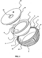
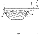
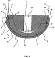
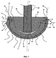
- the figures 1 and 3 are exploded views respectively in perspective and in section, and the figure 4 is a sectional view of the elements of figures 1 and 3 assembled.
- the acetabulum is packaged assembled in the sterile state with the permanent ceramic articular insert 4 permanently engaged in the insertion cup 1.
- the insertion cup 1 comprises a peripheral receiving structure 8, able to receive attachment of an acetabular impactor and shaped so that the impactor can be attached to the acetabulum in the presence of the permanent ceramic articular insert 4 permanently engaged in the insertion cup 1.
- the definitive articular articular insert 4 has a small thickness E 'to allow the use of a large diameter prosthetic femoral head.
- the thickness of the definitive immovable articular insert 4 is therefore substantially equal to the thickness E 'represented on the figures 3 , 4 and 6 to 8 .
- a small thickness E ' is chosen in order to increase the diameter of the prosthetic femoral head (not shown) intended to be inserted into the concave articular surface 7 of the definitive immovable articular insert 4 (case a single mobility cup of the type described in the document EP 1 290 992 A1 ) or to allow the use of a movable articular insert (not shown) intended to receive the prosthetic femoral head (in the case of a dual mobility acetabulum of the type described in the document WO 2004/069091 ).
- the thickness E ' is chosen so that the definitive immovable articular insert 4 can endure, without premature wear or deterioration, the stresses occurring during normal use of a hip prosthesis by a patient.
- thin E 'thickness means a thickness E' less than or equal to about 4 mm, preferably less than or equal to 3.5 mm. To do this, it is possible to use a ceramic such as that described in the document EP 1 188 729 .
- the thickness of an insertion cup To characterize the thickness of an insertion cup, its thickness is generally considered in the vicinity of the upper edge of its concave receiving face.
- the thickness of the insertion cup 1 is therefore substantially equal to the thickness E represented on the figures 3 and 6 to 9 .
- This thickness E is the average thickness of the insertion cup 1 in the vicinity of the annular edge 9 of the concave receiving face 3 of the insertion cup 1.
- Thin thickness E is a thickness E less than or equal to about 4 mm, preferably less than or equal to 3 mm. , but greater than 2 mm to ensure sufficient mechanical strength.
- the insertion cup 1 comprises a peripheral receiving structure 8 which protrudes beyond the receiving face 6 of the definitive immovable articular insert 4 inserted into the insertion cup 1.
- the peripheral receiving structure 8 constitutes a short annular extension of insertion cup wall 1, with, in this embodiment, an inner receiving annular surface 10 (materialized by dotted lines on the figures 4 and 8 ) developing in continuity with the concave receiving face 3 of the insertion cup 1.
- a laying insert and orientation 11 removably attached to the peripheral receiving structure 8 of the insertion cup 1.
- the insertion and orientation insert It can thus be secured to the insertion cup 1 in the presence of the permanent ceramic articular insert 4 permanently engaged in the insertion cup 1 ( figures 4 , 5 , 6 , 7 and 9 ), and can be separated from the insertion cup 1 (as it is best represented on the figure 8 ) after impaction of the acetabulum in the acetabulum of the patient.
- the laying and orienting insert 11 comprises an assembly structure 12 on which a detachable impactor can be fixed.
- the assembly structure 12 comprises a threaded fastening hole 13 made in the laying and orienting insert 11.
- This threaded fastening hole 13 allows the screwing of a threaded portion 14 of the impactor 15 (FIG. figures 5 and 6 ).
- the peripheral receiving structure 8 comprises an annular groove 16 in which an annular rib 17 is engaged on the laying and orienting insert 11.
- the annular rib 17 is resiliently engaged in the annular groove 16 when of the assembly of the insertion cup 1, the definitive articular insert 4 and the insertion and positioning insert 11, schematically assembled on the figure 3 by the arrows 30 and 31.
- annular groove 16 and the annular rib 17 are continuous.
- the continuous nature of the annular groove 16 and the annular rib 17 allows a homogeneous and maximum retention of the insert and orientation insert 11 in the insertion cup 1 along its entire periphery.
- annular rib 17 and annular groove 16 can be envisaged.
- the annular groove 16 and the annular rib 17 may be discontinuous.
- annular groove 16 is provided on the inner annular receiving surface of the receiving peripheral structure 8 of the insertion cup 1, while the annular rib 17 of the laying and orienting insert 11 is a rib annular 17 outer, engaged elastically in the annular groove 16.
- the laying insert and orientation 11 does not protrude laterally beyond the periphery of the insertion cup 1. There is therefore no risk of conflict, during impaction and orientation of the acetabulum, between the placement and orientation insert 11 and the bone material of the patient's pelvis on the periphery of its acetabular cavity.
- the peripheral receiving structure 8 and the laying and orienting insert 11 comprise threads cooperating together to fix the positioning and positioning insert 11 removably by screwing on the peripheral receiving structure 8. Threading of the peripheral receiving structure 8 is internal when the threading of the laying and orienting insert 11 is external, and the threading of the peripheral receiving structure 8 is external when the threading of the laying insert and of orientation 11 is an internal thread.
- the acetabulum is conditioned, assembled in the sterile state, with the permanent ceramic articular insert 4 permanently engaged in the insertion cup 1 ( figure 4 ).
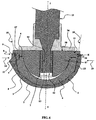
- the surgeon uses an impactor 15 with a threaded end portion 14 which is fixed in the threaded fixing hole 13 made in the insertion and orientation insert 11 ( figures 5 and 6 ).
- the impactor 15 comprises a flange 26 bearing against the upper face 28 of the laying and orienting insert 11.
- the flange 26 distributes the impaction and orientation forces on the insert insert and Orientation 11.
- the impactor 15 allows the surgeon to apply a force of depression of the insertion cup 1 into the acetabulum of the bone, to apply rotational torques to adjust the orientation of the insertion cup. 1, and makes it possible to maintain the insertion cup 1 in a fixed position for a sufficient duration, in particular for taking a cement between the external surface of the insertion cup 1 and the acetabulum of the bone.
- the insertion cup 1 undergoes significant forces which, because of the small thickness E ( figure 6 ), could deform the insertion cup 1 alone in contact with the pelvic bone of the patient. This deformation of the insertion cup 1 is prevented, during the impaction of the insertion cup 1, by the presence of the definitive immovable articular insert 4 engaged in the insertion cup 1.
- the permanent articular insert 4 ceramic permanent is sufficiently rigid and strong to counter any deformation.
- the insertion cup 1, the definitive immovable articular insert 4 and the placement and orientation insert 11 can advantageously be packaged together in the sterile state. The surgeon can then impact in a single operation the insertion cup 1 with its definitive articular insert 4. The surgeon thus gains a valuable operative time, which helps to reduce the operational risks related to a possible infection.
- the surgeon removes the insertion and orientation insert 11 from the peripheral receiving structure 8 of the insertion cup 1 and The femoral prosthetic head is located in the concave articular surface 7 of the definitive articular insert 4.
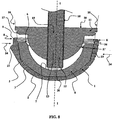
- the step of separating the insertion and orientation insert 11 and the insertion cup 1 is shown more particularly on the Figures 7 to 9 .
- a first method of separating the insertion and orientation insert 11 is illustrated on the figures 7 and 8 .
- the character emerging from the threaded fixing hole 13 makes it possible to engage a disconnecting tool 18 comprising a threaded rod 19 adapted to be screwed into the fixing hole 13.
- the disconnecting tool 18 comprises a distal end 20 shaped to bear against the concave articular surface 7 of the definitive articular insert 4 during the screwing of the threaded rod 19 in the fixing hole 13 of the laying and orientation insert 11.
- Screwing the threaded rod 19 into the fixing hole 13 allows the positioning and orientation insert 11 to be removed from the insertion cup 1 in the axial direction II until it is completely detached ( figure 8 ) where the annular rib 17 of the laying and orienting insert 11 has escaped elastically to the annular groove 16.
- the distal end 20 of the uncoupling tool 18 is adapted to bear against the surface Concave joint 7 of the definitive articular insert 4 without degrading it.
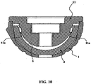
- a second method of separating the insertion and orientation insert 11 is illustrated on the figure 9 .
- the positioning and positioning insert 11 is shaped so that there remains a free space S between the placement and orientation insert 11 and the bottom of the concave articular surface 7 of the articular insert 4 immovable once the laying insert and orientation 11 attached to the peripheral receiving structure 8 of the insertion cup 1.
- the laying and orientation insert 11 is in sealing contact along its periphery in the short annular extension 9 of the insertion cup 1.
- the open nature of the fixing hole 13 makes it possible to place in communication with the outside the free space S formed between the positioning and orientation insert 11 and the definitive immovable articular insert 4.
- the fixing hole 13 is dimensioned to allow the engagement of the end of a conduit 21 for supplying fluid under pressure.
- the pipe 21 makes it possible to bring a fluid from the outside into the free space S as illustrated by the arrow 22.
- the fluid will then fill the free space S, and the fluid pressure in the pipe 21 and in the free space S will cause a thrust axis II on the laying insert and orientation 11 in the direction defined by the arrow 32.
- the fluid supply line 21 may therefore be the end of a syringe.
- the use of a syringe is particularly interesting in the medical setting. It is indeed a common medical object, which can be sterilized and is easily used in an operating room.
- the fluid supply conduit 21 may be a tubular portion of the impactor itself.
- the fluid used for the separation of the insertion cup 1 and the insertion and positioning insert 11 may be water or physiological saline which are fluids usable and widespread in the operating rooms.
- the positioning and orientation insert 11 is fixed on the peripheral receiving structure 8 of the insertion cup 1 at a small distance e from the receiving internal face 6 of the definitive ceramic articular insert 4 .
- a gap e allows a reliable and secure engagement of the annular rib 17 in the annular groove 16 along its entire periphery.
- the placement and orientation insert 11 will deform very slightly under the axial impaction forces of axis II to come to a patient. even smaller distance from or in support on the inner receiving face 6 of the permanent articular insert 4 permanent ceramic or on its peripheral edge.
- the definitive immovable articular insert 4 allows the transmission of impaction and orientation of the acetabulum.
- the permanent immovable articular insert 4 is furthermore kept pressed against the concave receiving face 3 of the insertion cup 1, which guarantees that the definitive immovable articular insert 4 contributes to the rigidity of the insertion cup 1 and prevents any deformation thereof.
- the laying insert and orientation 11 comprises a resilient rib 11a projecting which bears elastically against the ceramic articular insert 4 in order to keep it plated in the insertion cup 1.
- the rib 11a is in the form of an annular lip, and abuts against the inner receiving face 6.
- the presence of the definitive immovable ceramic articular insert 4 engaged in the insertion cup 1 prohibits the use of fixing screws to fix the insertion cup 1 in the acetabular cavity of the patient's pelvis passing through holes passing through the insertion cup from its concave receiving face towards its convex external anchoring face 2.
- This paw of external fixation 25 includes a lumen 29 through which a screw (not shown) passes to engage the pelvic bone of the patient.
- the insertion cup 1 may be metallic, made of titanium or an alloy of chromium and cobalt steel.
- the insertion cup 1 may also be PEEK (polyetheretherketone) or any other suitable material.
- the outer convex face 2 of the insertion cup 1 may advantageously be covered with a hydroxyapatite (PAH) layer.
- PAH hydroxyapatite
Landscapes
- Health & Medical Sciences (AREA)
- Orthopedic Medicine & Surgery (AREA)
- Transplantation (AREA)
- Animal Behavior & Ethology (AREA)
- Public Health (AREA)
- Engineering & Computer Science (AREA)
- Biomedical Technology (AREA)
- Heart & Thoracic Surgery (AREA)
- Vascular Medicine (AREA)
- Life Sciences & Earth Sciences (AREA)
- Cardiology (AREA)
- General Health & Medical Sciences (AREA)
- Oral & Maxillofacial Surgery (AREA)
- Veterinary Medicine (AREA)
- Physical Education & Sports Medicine (AREA)
- Prostheses (AREA)
- Acyclic And Carbocyclic Compounds In Medicinal Compositions (AREA)
- Catching Or Destruction (AREA)
- Pharmaceuticals Containing Other Organic And Inorganic Compounds (AREA)
- Hydrogenated Pyridines (AREA)
- Apparatus For Disinfection Or Sterilisation (AREA)
Claims (15)
- Verfahren zur Herstellung einer prothetischen Hüftgelenkpfanne mit folgenden Schritten:a) Bereitstellen eines metallischen Pfanneneinsatzes (1), der eine konkave Aufnahmefläche (3) und eine periphere Aufnahmestruktur (8) aufweist,b) Bereitstellen eines Gelenkeinsatzes (4) aus Keramik, der unbeweglich und endgültig sein wird, der eine äußere Fläche (5) hat, und eine innere Aufnahmefläche (6) hat, die eine konkave Gelenkfläche (7) hat,c) Einsetzen der äußeren Fläche (5) des Gelenkeinsatzes (4) in die konkave Aufnahmefläche (3) des Pfanneneinsatzes (1),c1) Befestigen eines Positionierungs- und Orientierungs-einsatzes (11) an der peripheren Aufnahmestruktur (8) des Pfanneneinsatzes (1) in reversibler Weise, der eine Montagestruktur (12) trägt, an der ein Montageschaft (15) in abnehmbarer Weise fixiert werden kann,d) Sterilisieren der so geformten Gesamtheit in einer mikrobiologischen Schutzhülle.
- Verfahren nach Anspruch 1, dadurch gekennzeichnet, daß der Schritt d) der Sterilisation durch Bestrahlung mit Gamma-Strahlen durchgeführt wird.
- Verfahren nach einem der Ansprüche 1 oder 2, dadurch gekennzeichnet, daß der Positionierungs- und Orientierungseinsatz (11) aus Polyethylen ist.
- Verfahren nach irgendeinem der Ansprüche 1 bis 3, dadurch gekennzeichnet, daß die Montagestruktur (12) ein Befestigungsloch (13) mit Gewinde aufweist, das in dem Positionierungs- und Orientierungseinsatz (11) angebracht ist und das Einschrauben eines Gewindeteiles (14) entsprechend dem Montageschaft (15) erlaubt.
- Verfahren nach irgendeinem der Ansprüche 1 bis 4, dadurch gekennzeichnet, daß der Positionierungs- und Orientierungseinsatz (11), der an dem Pfanneneinsatz (1) befestigt ist, im Anschlag zur inneren Aufnahmefläche (6) des endgültig unbeweglichen Gelenkeinsatzes (4) aus Keramik ist.
- Verfahren nach Anspruch 1 oder nach einem der Ansprüche 3 oder 4 nach ihrer Verbindung mit dem Anspruch 1, dadurch gekennzeichnet, daß:- der Positionierungs- und Orientierungseinsatz (11), der an dem Pfanneneinsatz (1) befestig ist, in geringem Abstand (e) zur inneren Aufnahmefläche (6) des endgültig unbeweglichen Gelenkeinsatzes (4) aus Keramik ist,- der Schritt d) der Sterilisation durch Bestrahlung mit Gamma-Strahlen durchgeführt wird.
- Verfahren nach irgendeinem der Ansprüche 1 bis 6, dadurch gekennzeichnet, daß dem Positionierungs- und Orientierungseinsatz (11), der an dem Pfanneneinsatz (1) befestigt ist, eine oder mehrere elastische überstehende Rippen (11a) hat, die an dem endgültig unbeweglichen Gelenkeinsatz (4) aus Keramik in Anschlag kommen, um ihn in dem Pfanneneinsatz (1) zu halten.
- Verfahren nach irgendeinem der Ansprüche 1 bis 7, dadurch gekennzeichnet, daß der Pfanneneinsatz (1) in Nachbarschaft zu ihrem ringförmigen Rand (9) eine Dicke (E) hat, die kleiner oder gleich ungefähr 4 mm ist und größer als 2 mm.
- Verfahren nach irgendeinem der Ansprüche 1 bis 8, dadurch gekennzeichnet, daß der endgültig unbewegliche Gelenkeinsatz (4) aus Keramik eine Dicke (E') von kleiner oder gleich ungefähr 4 mm hat.
- Verfahren nach irgendeinem der Ansprüche 1 bis 9, dadurch gekennzeichnet, daß die periphere Aufnahmestruktur (8) ringförmig ist.
- Verfahren nach irgendeinem der Ansprüche 1 bis 10, dadurch gekennzeichnet, daß:- die periphere Aufnahmestruktur (8) eine ringförmige kontinuierliche oder diskontinuierliche Hohlkehle (16) hat,- der Positionierungs- und Orientierungseinsatz (11) einen ringförmigen, kontinuierlichen oder diskontinuierlichen Vorsprung (17) hat, der elastisch in die ringförmige Hohlkehle (16) eingreift.
- Verfahren nach Anspruch 11, dadurch gekennzeichnet, daß:- die ringförmige Hohlkehle (16) kontinuierlich ist,- der ringförmige Vorsprung (17) des Positionierungs- und Orientierungseinsatzes (11) ein äußerer kontinuierlicher Vorsprung (17) ist, der elastisch in die ringförmige Hohlkehle (16) eingreift.
- Verfahren nach irgendeinem der Ansprüche 1 bis 10, dadurch gekennzeichnet, daß:- die periphere Aufnahmestruktur (8) ein internes oder externes Gewinde aufweist,- der Positionierungs- und Orientierungseinsatz (11) eine äußeres oder inneres Gewinde aufweist, das mit dem Gewinde der periphere Aufnahmestruktur (8) zusammen arbeitet, um den Positionierungs- und Orientierungseinsatz (11) in abnehmbarer Weise mittels Einschrauben an der peripheren Aufnahmestruktur (8) zu befestigen.
- Verfahren nach der Anspruch 4, dadurch gekennzeichnet, daß das Befestigungsloch (13), das mit einem Gewinde versehen ist, ein Durchgangsloch ist, das ausgebildet ist, um mit einem Ausbauwerkzeug (18) zusammen zu arbeiten, das einen Gewindeschaft (19) aufweist, der ausgebildet ist, um sich in das Befestigungsloch (13) einzuschrauben und der ein distales Ende (20) aufweist, das ausgebildet ist, um in Anschlag gegen die konkave Gelenkfläche (7) des endgültig unbeweglichen Gelenkeinsatzes (4) in Anschlag zu kommen, beim Einschrauben des Gewindeschaftes (19) in das Befestigungsloch (13) des Positionierungs- und Orientierungseinsatzes (11).
- Verfahren nach Anspruch 4, dadurch gekennzeichnet, daß:- der Positionierungs- und Orientierungseinsatz (11) derart ausgebildet ist, daß er einen freien Raum (S) zwischen dem Positionierungs- und Orientierungseinsatz (11) und dem Boden der konkaven Gelenkfläche (7) des endgültig unbeweglichen Gelenkeinsatzes (4) läßt, wenn der Positionierungs- und Orientierungseinsatz (11) an der peripheren Aufnahmestruktur (8) des Pfanneneinsatzes (1) befestigt ist,- der Positionierungs- und Orientierungseinsatz (11) mit seinem Umfang in dichtem Kontakt in der peripheren Aufnahmestruktur (8) des Pfanneneinsatzes (1) ist,- das Befestigungsloch (13) ein Durchgangsloch ist, das eine Verbindung mit dem äußeren freien Raum (S) zwischen dem Positionierungs- und Orientierungseinsatz (11) und dem endgültig unbeweglichen Gelenkeinsatz (4) läßt und dimensioniert ist, um dort das Ende einer Spritze in dichter Weise eingreifen zu lassen.
Applications Claiming Priority (2)
| Application Number | Priority Date | Filing Date | Title |
|---|---|---|---|
| FR0752558A FR2911062B1 (fr) | 2007-01-08 | 2007-01-08 | Cotyle a interface sterile |
| EP08700220.0A EP2101688B1 (de) | 2007-01-08 | 2008-01-08 | Gelenkpfanne mit steriler fläche |
Related Parent Applications (3)
| Application Number | Title | Priority Date | Filing Date |
|---|---|---|---|
| EP08700220.0 Division | 2008-01-08 | ||
| EP08700220.0A Division-Into EP2101688B1 (de) | 2007-01-08 | 2008-01-08 | Gelenkpfanne mit steriler fläche |
| EP08700220.0A Division EP2101688B1 (de) | 2007-01-08 | 2008-01-08 | Gelenkpfanne mit steriler fläche |
Publications (4)
| Publication Number | Publication Date |
|---|---|
| EP2189135A1 EP2189135A1 (de) | 2010-05-26 |
| EP2189135B1 EP2189135B1 (de) | 2011-11-23 |
| EP2189135B3 true EP2189135B3 (de) | 2016-06-08 |
| EP2189135B9 EP2189135B9 (de) | 2016-08-31 |
Family
ID=38330510
Family Applications (2)
| Application Number | Title | Priority Date | Filing Date |
|---|---|---|---|
| EP08700220.0A Active EP2101688B1 (de) | 2007-01-08 | 2008-01-08 | Gelenkpfanne mit steriler fläche |
| EP10153901.3A Active EP2189135B9 (de) | 2007-01-08 | 2008-01-08 | Gelenkpfanne mit steriler Fläche |
Family Applications Before (1)
| Application Number | Title | Priority Date | Filing Date |
|---|---|---|---|
| EP08700220.0A Active EP2101688B1 (de) | 2007-01-08 | 2008-01-08 | Gelenkpfanne mit steriler fläche |
Country Status (19)
| Country | Link |
|---|---|
| US (3) | US8764843B2 (de) |
| EP (2) | EP2101688B1 (de) |
| JP (2) | JP5437075B2 (de) |
| KR (2) | KR101422463B1 (de) |
| CN (2) | CN102512268B (de) |
| AT (1) | ATE534349T3 (de) |
| AU (2) | AU2008247066B2 (de) |
| BR (2) | BRPI0806331B8 (de) |
| CA (2) | CA2888895C (de) |
| DE (2) | DE08700220T1 (de) |
| ES (2) | ES2478669T3 (de) |
| FR (1) | FR2911062B1 (de) |
| IL (2) | IL199717A (de) |
| MA (1) | MA31177B1 (de) |
| MX (1) | MX2009007298A (de) |
| PT (2) | PT2189135E (de) |
| RU (2) | RU2599203C2 (de) |
| WO (1) | WO2008135868A1 (de) |
| ZA (1) | ZA200904848B (de) |
Families Citing this family (36)
| Publication number | Priority date | Publication date | Assignee | Title |
|---|---|---|---|---|
| US7905919B2 (en) | 2006-11-07 | 2011-03-15 | Biomedflex Llc | Prosthetic joint |
| WO2008058205A1 (en) | 2006-11-07 | 2008-05-15 | Biomedflex, Llc | Medical implants |
| US20110166671A1 (en) | 2006-11-07 | 2011-07-07 | Kellar Franz W | Prosthetic joint |
| US8029574B2 (en) | 2006-11-07 | 2011-10-04 | Biomedflex Llc | Prosthetic knee joint |
| US8512413B2 (en) | 2006-11-07 | 2013-08-20 | Biomedflex, Llc | Prosthetic knee joint |
| US9005307B2 (en) | 2006-11-07 | 2015-04-14 | Biomedflex, Llc | Prosthetic ball-and-socket joint |
| US7914580B2 (en) * | 2006-11-07 | 2011-03-29 | Biomedflex Llc | Prosthetic ball-and-socket joint |
| US8070823B2 (en) | 2006-11-07 | 2011-12-06 | Biomedflex Llc | Prosthetic ball-and-socket joint |
| US8308812B2 (en) | 2006-11-07 | 2012-11-13 | Biomedflex, Llc | Prosthetic joint assembly and joint member therefor |
| FR2911062B1 (fr) * | 2007-01-08 | 2009-07-03 | Thomas Gradel | Cotyle a interface sterile |
| EP2008619B1 (de) | 2007-06-26 | 2016-11-02 | Finsbury (Development) Limited | Prothese |
| FR2950525B1 (fr) | 2009-09-28 | 2013-05-10 | Thomas Gradel | Cotyle prothetique de hanche a fixation externe |
| GB0922339D0 (en) | 2009-12-21 | 2010-02-03 | Mcminn Derek J W | Acetabular cup prothesis and introducer thereof |
| FR2961387B1 (fr) * | 2010-06-17 | 2013-06-07 | Thomas Gradel | Cotyle ceramique a fixation externe |
| CA2807948A1 (en) * | 2010-08-13 | 2012-02-16 | Smith & Nephew, Inc. | Surgical guides |
| US9023112B2 (en) * | 2011-02-24 | 2015-05-05 | Depuy (Ireland) | Maintaining proper mechanics THA |
| DE102011050019A1 (de) | 2011-04-29 | 2012-10-31 | Aesculap Ag | Chirurgische Adaptervorrichtung für ein Gelenkimplantat und chirurgisches System |
| DE202011050009U1 (de) | 2011-04-29 | 2011-07-14 | Aesculap Ag | Chirurgische Adaptervorrichtung für ein Gelenkimplantat und chirurgisches System |
| EP2704651A4 (de) * | 2011-05-03 | 2014-10-08 | Smith & Nephew Inc | Patientenspezifische führungen für orthopädische implantate |
| EP2572679B1 (de) * | 2011-09-23 | 2015-07-15 | Greatbatch Medical SA | Halter für keramisches Implantat |
| ITUD20120179A1 (it) * | 2012-10-24 | 2014-04-25 | Limacorporate Spa | Protesi acetabolare e relativo procedimento di fabbricazione e di assemblaggio |
| US20150230926A1 (en) | 2014-02-18 | 2015-08-20 | Biomet Manufacturing, Llc | Method and device for reducing implant contamination from handling |
| FR3027510B1 (fr) * | 2014-10-23 | 2021-04-02 | Evolutis | Implant cotyloidien |
| ES2829910T3 (es) * | 2014-12-24 | 2021-06-02 | Matortho Ltd | Prótesis |
| CN104921846B (zh) * | 2015-07-06 | 2017-01-18 | 卢通成 | 一种抗磨损、不破裂的新型金属陶瓷股骨头及其制作方法 |
| EP3340939B1 (de) * | 2015-08-27 | 2025-10-15 | HIP Innovation Technology, LLC | Chirurgische tabletts zur entfernung von bestandteilen einer hüftprothese |
| CN105250053A (zh) * | 2015-11-10 | 2016-01-20 | 北京市春立正达医疗器械股份有限公司 | 一种全髋臼假体 |
| ES2700650T3 (es) * | 2016-04-12 | 2019-02-18 | Dedienne Sante | Conjunto para la implantación de un acetábulo en una cavidad acetabular |
| GB2551155A (en) * | 2016-06-07 | 2017-12-13 | Matortho Ltd | Prosthesis |
| US10456262B2 (en) | 2016-08-02 | 2019-10-29 | Howmedica Osteonics Corp. | Patient-specific implant flanges with bone side porous ridges |
| DE102016114368B3 (de) * | 2016-08-03 | 2017-11-16 | Aesculap Ag | Gelenkpfanne und Gelenkendoprothese |
| RU200675U1 (ru) * | 2020-03-20 | 2020-11-05 | федеральное государственное бюджетное образовательное учреждение высшего образования "Приволжский исследовательский медицинский университет" Министерства здравоохранения Российской Федерации (ФГБОУ ВО "ПИМУ" Минздрава России) | Устройство для изготовления цементного вертлужного компонента артикулирующего спейсера тазобедренного сустава |
| CN111329625A (zh) * | 2020-04-03 | 2020-06-26 | 苏州中科生物医用材料有限公司 | 一种髋关节双极头 |
| WO2022092144A1 (ja) * | 2020-10-29 | 2022-05-05 | ニプロ株式会社 | 寛骨臼コンポーネント |
| FR3117771B1 (fr) * | 2020-12-23 | 2023-02-24 | Soc Detudes De Recherches Et De Fabrication Serf | Dispositif d’engagement d’une tête sphérique dans un insert |
| US12064356B2 (en) | 2021-08-19 | 2024-08-20 | Howmedica Osteonics Corp. | Multi-size acetabular impactor |
Family Cites Families (30)
| Publication number | Priority date | Publication date | Assignee | Title |
|---|---|---|---|---|
| GB1325534A (en) * | 1969-08-11 | 1973-08-01 | Nat Res Dev | Prosthetic acetabular devices |
| US4715860A (en) * | 1985-08-23 | 1987-12-29 | The Regents Of The University Of California | Porous acetabular hip resurfacing |
| US5098437A (en) * | 1991-02-13 | 1992-03-24 | Pfizer Hospital Products Group, Inc. | Acetabular cup positioning insert |
| US5061270A (en) * | 1991-03-18 | 1991-10-29 | Aboczky Robert I | System for orienting, inserting and impacting an acetabular cup prosthesis |
| DE4337936A1 (de) * | 1993-11-06 | 1995-05-11 | Cerasiv Gmbh | Sphärische Hüftgelenkpfanne |
| US5486181A (en) * | 1994-08-04 | 1996-01-23 | Implex Corporation | Acetabular cup, method and tool and installing the same |
| US5702477A (en) * | 1996-05-09 | 1997-12-30 | Osteonics Corp. | Acetabular shell with supplemental support and method |
| DE19640747B4 (de) * | 1996-07-30 | 2006-04-13 | Cerasiv Gmbh Innovatives Keramik-Engineering | Hüftgelenkendoprothese |
| US6022357A (en) * | 1997-03-03 | 2000-02-08 | Aesculap Ag & Co. Kg | Surgical instrument |
| GB2323036B (en) | 1997-03-14 | 2001-04-11 | Finsbury | Prosthetic implant and surgical tool |
| US6132469A (en) * | 1997-11-07 | 2000-10-17 | Biomet, Inc. | Acetabular liner extractor |
| US6161695A (en) * | 1998-08-21 | 2000-12-19 | Depuy Orthopaedics, Inc. | Protective packaging unit |
| AU4366301A (en) * | 2000-03-14 | 2001-09-24 | Smith & Nephew Inc | Variable geometry rim surface acetabular shell liner |
| AU783205C (en) | 2000-03-15 | 2006-08-17 | Depuy Orthopaedics, Inc. | Prosthetic cup assembly which includes components possessing self-locking taper |
| DE10026157A1 (de) * | 2000-05-26 | 2002-02-28 | Link Waldemar Gmbh Co | Verfahren und Instrumentarium zum Einsetzen einer Hüftpfannenprothese |
| EP1188729A3 (de) | 2000-09-13 | 2004-03-31 | CeramTec AG Innovative Ceramic Engineering | Verbundwerkstoff mit plateletverstärkter Aluminiumoxidkeramik-Matrix |
| US7597715B2 (en) * | 2005-04-21 | 2009-10-06 | Biomet Manufacturing Corp. | Method and apparatus for use of porous implants |
| FR2827154B1 (fr) * | 2001-07-16 | 2004-04-30 | Jean Yves Lazennec | Implant cotyloidien pour prothese de hanche |
| WO2004069091A2 (fr) | 2001-07-16 | 2004-08-19 | Ceram Concept L.L.C. | Implant cotyloidien pour prothese de hanche |
| KR100458638B1 (ko) * | 2001-09-10 | 2004-12-03 | 삼성테크윈 주식회사 | 인공 고관절용 비구 컵 |
| GB0122002D0 (en) * | 2001-09-11 | 2001-10-31 | Benoist Girard Sas | Acetabular cup |
| US6682567B1 (en) * | 2001-09-19 | 2004-01-27 | Biomet, Inc. | Method and apparatus for providing a shell component incorporating a porous ingrowth material and liner |
| FR2850010B1 (fr) * | 2003-01-17 | 2005-12-02 | Tornier Sa | Ancillaire de pose d'un cotyle prothetique pour une prothese de hanche |
| DE10304102A1 (de) | 2003-01-31 | 2004-08-12 | Ceram Tec Ag Innovative Ceramic Engineering | Hüftgelenkprothese |
| US7344565B2 (en) * | 2003-02-04 | 2008-03-18 | Wright Medical Technology, Inc. | Acetabular component insertion and extraction tool for use therewith, and method of locking an acetabular component to an insertion and extraction tool |
| RU2240757C1 (ru) * | 2003-07-02 | 2004-11-27 | Закрытое акционерное общество "ЭндоИмплант" | Эндопротез вертлужного компонента тазобедренного сустава |
| US20050228394A1 (en) * | 2004-03-31 | 2005-10-13 | Diane Bihary | Suction inserter |
| FR2876278B1 (fr) * | 2004-10-13 | 2007-10-26 | Thomas Gradel | Instruments de pose de cotyle |
| RU66190U1 (ru) * | 2006-12-27 | 2007-09-10 | Константин Сергеевич Сергеев | Вертлужный компонент эндопротеза тазобедренного сустава |
| FR2911062B1 (fr) * | 2007-01-08 | 2009-07-03 | Thomas Gradel | Cotyle a interface sterile |
-
2007
- 2007-01-08 FR FR0752558A patent/FR2911062B1/fr active Active
-
2008
- 2008-01-08 KR KR1020107018842A patent/KR101422463B1/ko not_active Expired - Fee Related
- 2008-01-08 KR KR1020097016522A patent/KR101422462B1/ko not_active Expired - Fee Related
- 2008-01-08 EP EP08700220.0A patent/EP2101688B1/de active Active
- 2008-01-08 BR BRPI0806331A patent/BRPI0806331B8/pt active IP Right Grant
- 2008-01-08 JP JP2009544482A patent/JP5437075B2/ja not_active Expired - Fee Related
- 2008-01-08 AT AT10153901T patent/ATE534349T3/de unknown
- 2008-01-08 RU RU2012109941/14A patent/RU2599203C2/ru active
- 2008-01-08 DE DE08700220T patent/DE08700220T1/de active Pending
- 2008-01-08 PT PT10153901T patent/PT2189135E/pt unknown
- 2008-01-08 CA CA2888895A patent/CA2888895C/fr active Active
- 2008-01-08 ES ES08700220.0T patent/ES2478669T3/es active Active
- 2008-01-08 DE DE10153901T patent/DE10153901T1/de active Granted
- 2008-01-08 MX MX2009007298A patent/MX2009007298A/es active IP Right Grant
- 2008-01-08 CA CA2674624A patent/CA2674624C/fr active Active
- 2008-01-08 AU AU2008247066A patent/AU2008247066B2/en active Active
- 2008-01-08 CN CN201110303378.5A patent/CN102512268B/zh active Active
- 2008-01-08 BR BRPI0823325A patent/BRPI0823325B8/pt active IP Right Grant
- 2008-01-08 US US12/522,162 patent/US8764843B2/en active Active
- 2008-01-08 ES ES10153901.3T patent/ES2378220T7/es active Active
- 2008-01-08 PT PT87002200T patent/PT2101688E/pt unknown
- 2008-01-08 CN CN2008800018807A patent/CN101600403B/zh not_active Expired - Fee Related
- 2008-01-08 RU RU2009130372/14A patent/RU2453293C2/ru active
- 2008-01-08 EP EP10153901.3A patent/EP2189135B9/de active Active
- 2008-01-08 WO PCT/IB2008/050047 patent/WO2008135868A1/fr not_active Ceased
-
2009
- 2009-07-07 IL IL199717A patent/IL199717A/en active IP Right Grant
- 2009-07-10 ZA ZA200904848A patent/ZA200904848B/xx unknown
- 2009-08-06 MA MA32156A patent/MA31177B1/fr unknown
-
2010
- 2010-08-17 US US12/857,725 patent/US8845748B2/en active Active
- 2010-08-27 AU AU2010214705A patent/AU2010214705C1/en active Active
-
2012
- 2012-08-30 IL IL221699A patent/IL221699A/en active IP Right Grant
-
2013
- 2013-07-23 JP JP2013152196A patent/JP5671106B2/ja not_active Expired - Fee Related
-
2014
- 2014-08-27 US US14/470,079 patent/US9168143B2/en active Active
Also Published As
Similar Documents
| Publication | Publication Date | Title |
|---|---|---|
| EP2189135B3 (de) | Gelenkpfanne mit steriler Fläche | |
| EP1811928B1 (de) | Instrumente zum einbringen einer hüftpfanne | |
| EP2488128B1 (de) | Hüftgelenkpfanne mit hoher retentionskapazität | |
| CA2775791C (fr) | Procede de fabrication d'un cotyle prothetique de hanche | |
| EP2254484A2 (de) | Schneideelement für ein werkzeug zur formung einer knochenoberfläche sowie damit ausgestattetes werkzeug | |
| EP2582329A1 (de) | Verfahren zur herstellung eines gelenkpfanne aus keramik | |
| EP2205187A2 (de) | Oberschenkelkomponente für eine hüftprothese und hüfttotalendoprothese damit | |
| FR2686015A1 (fr) | Prothese de hanche. | |
| FR2896984A1 (fr) | Prothese cotyloidienne et son procede pour une implantation sans ciment. | |
| FR2935262A1 (fr) | Cotyle prothetique articulaire. |
Legal Events
| Date | Code | Title | Description |
|---|---|---|---|
| PUAI | Public reference made under article 153(3) epc to a published international application that has entered the european phase |
Free format text: ORIGINAL CODE: 0009012 |
|
| AC | Divisional application: reference to earlier application |
Ref document number: 2101688 Country of ref document: EP Kind code of ref document: P |
|
| AK | Designated contracting states |
Kind code of ref document: A1 Designated state(s): AT BE BG CH CY CZ DE DK EE ES FI FR GB GR HR HU IE IS IT LI LT LU LV MC MT NL NO PL PT RO SE SI SK TR |
|
| RTI1 | Title (correction) |
Free format text: ACETABULAR CUP COMPRISING A STERILE INTERFACE |
|
| 17P | Request for examination filed |
Effective date: 20100617 |
|
| GBC | Gb: translation of claims filed (gb section 78(7)/1977) | ||
| DET | De: translation of patent claims | ||
| REG | Reference to a national code |
Ref country code: HK Ref legal event code: DE Ref document number: 1143304 Country of ref document: HK |
|
| GRAP | Despatch of communication of intention to grant a patent |
Free format text: ORIGINAL CODE: EPIDOSNIGR1 |
|
| RIC1 | Information provided on ipc code assigned before grant |
Ipc: A61F 2/46 20060101ALI20110407BHEP Ipc: A61F 2/34 20060101AFI20110407BHEP |
|
| GRAS | Grant fee paid |
Free format text: ORIGINAL CODE: EPIDOSNIGR3 |
|
| GRAA | (expected) grant |
Free format text: ORIGINAL CODE: 0009210 |
|
| AC | Divisional application: reference to earlier application |
Ref document number: 2101688 Country of ref document: EP Kind code of ref document: P |
|
| AK | Designated contracting states |
Kind code of ref document: B1 Designated state(s): AT BE BG CH CY CZ DE DK EE ES FI FR GB GR HR HU IE IS IT LI LT LU LV MC MT NL NO PL PT RO SE SI SK TR |
|
| REG | Reference to a national code |
Ref country code: GB Ref legal event code: FG4D Free format text: NOT ENGLISH |
|
| REG | Reference to a national code |
Ref country code: CH Ref legal event code: EP |
|
| REG | Reference to a national code |
Ref country code: IE Ref legal event code: FG4D Free format text: LANGUAGE OF EP DOCUMENT: FRENCH |
|
| REG | Reference to a national code |
Ref country code: DE Ref legal event code: R096 Ref document number: 602008011623 Country of ref document: DE Effective date: 20120202 |
|
| REG | Reference to a national code |
Ref country code: PT Ref legal event code: SC4A Free format text: AVAILABILITY OF NATIONAL TRANSLATION Effective date: 20120208 Ref country code: CH Ref legal event code: NV Representative=s name: ZIMMERLI, WAGNER & PARTNER AG |
|
| REG | Reference to a national code |
Ref country code: NL Ref legal event code: T3 |
|
| REG | Reference to a national code |
Ref country code: SE Ref legal event code: TRGR |
|
| REG | Reference to a national code |
Ref country code: ES Ref legal event code: FG2A Ref document number: 2378220 Country of ref document: ES Kind code of ref document: T3 Effective date: 20120410 |
|
| LTIE | Lt: invalidation of european patent or patent extension |
Effective date: 20111123 |
|
| REG | Reference to a national code |
Ref country code: GR Ref legal event code: EP Ref document number: 20120400357 Country of ref document: GR Effective date: 20120322 |
|
| PG25 | Lapsed in a contracting state [announced via postgrant information from national office to epo] |
Ref country code: LT Free format text: LAPSE BECAUSE OF FAILURE TO SUBMIT A TRANSLATION OF THE DESCRIPTION OR TO PAY THE FEE WITHIN THE PRESCRIBED TIME-LIMIT Effective date: 20111123 Ref country code: NO Free format text: LAPSE BECAUSE OF FAILURE TO SUBMIT A TRANSLATION OF THE DESCRIPTION OR TO PAY THE FEE WITHIN THE PRESCRIBED TIME-LIMIT Effective date: 20120223 Ref country code: IS Free format text: LAPSE BECAUSE OF FAILURE TO SUBMIT A TRANSLATION OF THE DESCRIPTION OR TO PAY THE FEE WITHIN THE PRESCRIBED TIME-LIMIT Effective date: 20120323 |
|
| PG25 | Lapsed in a contracting state [announced via postgrant information from national office to epo] |
Ref country code: SI Free format text: LAPSE BECAUSE OF FAILURE TO SUBMIT A TRANSLATION OF THE DESCRIPTION OR TO PAY THE FEE WITHIN THE PRESCRIBED TIME-LIMIT Effective date: 20111123 Ref country code: LV Free format text: LAPSE BECAUSE OF FAILURE TO SUBMIT A TRANSLATION OF THE DESCRIPTION OR TO PAY THE FEE WITHIN THE PRESCRIBED TIME-LIMIT Effective date: 20111123 Ref country code: HR Free format text: LAPSE BECAUSE OF FAILURE TO SUBMIT A TRANSLATION OF THE DESCRIPTION OR TO PAY THE FEE WITHIN THE PRESCRIBED TIME-LIMIT Effective date: 20111123 |
|
| PG25 | Lapsed in a contracting state [announced via postgrant information from national office to epo] |
Ref country code: CY Free format text: LAPSE BECAUSE OF FAILURE TO SUBMIT A TRANSLATION OF THE DESCRIPTION OR TO PAY THE FEE WITHIN THE PRESCRIBED TIME-LIMIT Effective date: 20111123 |
|
| PG25 | Lapsed in a contracting state [announced via postgrant information from national office to epo] |
Ref country code: DK Free format text: LAPSE BECAUSE OF FAILURE TO SUBMIT A TRANSLATION OF THE DESCRIPTION OR TO PAY THE FEE WITHIN THE PRESCRIBED TIME-LIMIT Effective date: 20111123 Ref country code: SK Free format text: LAPSE BECAUSE OF FAILURE TO SUBMIT A TRANSLATION OF THE DESCRIPTION OR TO PAY THE FEE WITHIN THE PRESCRIBED TIME-LIMIT Effective date: 20111123 Ref country code: BG Free format text: LAPSE BECAUSE OF FAILURE TO SUBMIT A TRANSLATION OF THE DESCRIPTION OR TO PAY THE FEE WITHIN THE PRESCRIBED TIME-LIMIT Effective date: 20120223 Ref country code: EE Free format text: LAPSE BECAUSE OF FAILURE TO SUBMIT A TRANSLATION OF THE DESCRIPTION OR TO PAY THE FEE WITHIN THE PRESCRIBED TIME-LIMIT Effective date: 20111123 |
|
| REG | Reference to a national code |
Ref country code: HK Ref legal event code: GR Ref document number: 1143304 Country of ref document: HK |
|
| PG25 | Lapsed in a contracting state [announced via postgrant information from national office to epo] |
Ref country code: RO Free format text: LAPSE BECAUSE OF FAILURE TO SUBMIT A TRANSLATION OF THE DESCRIPTION OR TO PAY THE FEE WITHIN THE PRESCRIBED TIME-LIMIT Effective date: 20111123 Ref country code: PL Free format text: LAPSE BECAUSE OF FAILURE TO SUBMIT A TRANSLATION OF THE DESCRIPTION OR TO PAY THE FEE WITHIN THE PRESCRIBED TIME-LIMIT Effective date: 20111123 |
|
| PLBE | No opposition filed within time limit |
Free format text: ORIGINAL CODE: 0009261 |
|
| 26N | No opposition filed |
Effective date: 20120824 |
|
| REG | Reference to a national code |
Ref country code: DE Ref legal event code: R097 Ref document number: 602008011623 Country of ref document: DE Effective date: 20120824 |
|
| REG | Reference to a national code |
Ref country code: FR Ref legal event code: CL Name of requester: ADVANCED TECHNICAL FABRICATION, FR Effective date: 20130201 |
|
| PG25 | Lapsed in a contracting state [announced via postgrant information from national office to epo] |
Ref country code: FI Free format text: LAPSE BECAUSE OF FAILURE TO SUBMIT A TRANSLATION OF THE DESCRIPTION OR TO PAY THE FEE WITHIN THE PRESCRIBED TIME-LIMIT Effective date: 20111123 |
|
| PG25 | Lapsed in a contracting state [announced via postgrant information from national office to epo] |
Ref country code: MT Free format text: LAPSE BECAUSE OF FAILURE TO SUBMIT A TRANSLATION OF THE DESCRIPTION OR TO PAY THE FEE WITHIN THE PRESCRIBED TIME-LIMIT Effective date: 20111123 |
|
| REG | Reference to a national code |
Ref country code: CH Ref legal event code: NV Representative=s name: WAGNER PATENT AG, CH |
|
| PG25 | Lapsed in a contracting state [announced via postgrant information from national office to epo] |
Ref country code: HU Free format text: LAPSE BECAUSE OF FAILURE TO SUBMIT A TRANSLATION OF THE DESCRIPTION OR TO PAY THE FEE WITHIN THE PRESCRIBED TIME-LIMIT Effective date: 20080108 |
|
| REG | Reference to a national code |
Ref country code: DE Ref legal event code: R055 Ref document number: 602008011623 Country of ref document: DE |
|
| PLCP | Request for limitation filed |
Free format text: ORIGINAL CODE: EPIDOSNLIM1 |
|
| PLCQ | Request for limitation of patent found admissible |
Free format text: ORIGINAL CODE: 0009231 |
|
| TPAC | Observations filed by third parties |
Free format text: ORIGINAL CODE: EPIDOSNTIPA |
|
| LIM1 | Request for limitation found admissible |
Free format text: SEQUENCE NO: 1; FILED AFTER OPPOSITION PERIOD Filing date: 20150317 Effective date: 20150317 |
|
| PLCO | Limitation procedure: reply received to communication from examining division + time limit |
Free format text: ORIGINAL CODE: EPIDOSNLIR3 |
|
| TPAC | Observations filed by third parties |
Free format text: ORIGINAL CODE: EPIDOSNTIPA |
|
| REG | Reference to a national code |
Ref country code: FR Ref legal event code: PLFP Year of fee payment: 9 |
|
| PLCR | Communication despatched that request for limitation of patent was allowed |
Free format text: ORIGINAL CODE: 0009245 |
|
| REG | Reference to a national code |
Ref country code: DE Ref legal event code: R056 Ref document number: 602008011623 Country of ref document: DE Ref country code: DE Ref legal event code: R097 Ref document number: 602008011623 Country of ref document: DE |
|
| PLCN | Payment of fee for limitation of patent |
Free format text: ORIGINAL CODE: EPIDOSNRAL3 |
|
| PUAM | (expected) publication of b3 document |
Free format text: ORIGINAL CODE: 0009410 |
|
| STAA | Information on the status of an ep patent application or granted ep patent |
Free format text: STATUS: THE PATENT HAS BEEN LIMITED |
|
| REG | Reference to a national code |
Ref country code: CH Ref legal event code: AELM |
|
| REG | Reference to a national code |
Ref country code: NL Ref legal event code: FP |
|
| REG | Reference to a national code |
Ref country code: SE Ref legal event code: REB3 Effective date: 20160608 |
|
| REG | Reference to a national code |
Ref country code: FR Ref legal event code: PLFP Year of fee payment: 10 |
|
| REG | Reference to a national code |
Ref country code: GR Ref legal event code: EP Ref document number: 20160402114 Country of ref document: GR Effective date: 20161118 |
|
| REG | Reference to a national code |
Ref country code: FR Ref legal event code: PLFP Year of fee payment: 11 |
|
| REG | Reference to a national code |
Ref country code: AT Ref legal event code: UEP Ref document number: 534349 Country of ref document: AT Kind code of ref document: T |
|
| PGFP | Annual fee paid to national office [announced via postgrant information from national office to epo] |
Ref country code: PT Payment date: 20211125 Year of fee payment: 15 Ref country code: CZ Payment date: 20211126 Year of fee payment: 15 Ref country code: MC Payment date: 20211129 Year of fee payment: 15 |
|
| PGFP | Annual fee paid to national office [announced via postgrant information from national office to epo] |
Ref country code: GR Payment date: 20211126 Year of fee payment: 15 Ref country code: BE Payment date: 20211215 Year of fee payment: 15 |
|
| PGFP | Annual fee paid to national office [announced via postgrant information from national office to epo] |
Ref country code: LU Payment date: 20220119 Year of fee payment: 15 |
|
| PGFP | Annual fee paid to national office [announced via postgrant information from national office to epo] |
Ref country code: AT Payment date: 20211229 Year of fee payment: 15 |
|
| PGFP | Annual fee paid to national office [announced via postgrant information from national office to epo] |
Ref country code: SE Payment date: 20220117 Year of fee payment: 15 Ref country code: ES Payment date: 20220201 Year of fee payment: 15 |
|
| P01 | Opt-out of the competence of the unified patent court (upc) registered |
Effective date: 20230522 |
|
| PG25 | Lapsed in a contracting state [announced via postgrant information from national office to epo] |
Ref country code: CZ Free format text: LAPSE BECAUSE OF NON-PAYMENT OF DUE FEES Effective date: 20230108 |
|
| REG | Reference to a national code |
Ref country code: SE Ref legal event code: EUG |
|
| REG | Reference to a national code |
Ref country code: AT Ref legal event code: MM01 Ref document number: 534349 Country of ref document: AT Kind code of ref document: T Effective date: 20230108 |
|
| PG25 | Lapsed in a contracting state [announced via postgrant information from national office to epo] |
Ref country code: LU Free format text: LAPSE BECAUSE OF NON-PAYMENT OF DUE FEES Effective date: 20230108 |
|
| REG | Reference to a national code |
Ref country code: BE Ref legal event code: MM Effective date: 20230131 |
|
| PG25 | Lapsed in a contracting state [announced via postgrant information from national office to epo] |
Ref country code: SE Free format text: LAPSE BECAUSE OF NON-PAYMENT OF DUE FEES Effective date: 20230109 Ref country code: PT Free format text: LAPSE BECAUSE OF NON-PAYMENT OF DUE FEES Effective date: 20230710 Ref country code: AT Free format text: LAPSE BECAUSE OF NON-PAYMENT OF DUE FEES Effective date: 20230108 |
|
| PG25 | Lapsed in a contracting state [announced via postgrant information from national office to epo] |
Ref country code: GR Free format text: LAPSE BECAUSE OF NON-PAYMENT OF DUE FEES Effective date: 20230804 Ref country code: BE Free format text: LAPSE BECAUSE OF NON-PAYMENT OF DUE FEES Effective date: 20230131 |
|
| PGFP | Annual fee paid to national office [announced via postgrant information from national office to epo] |
Ref country code: NL Payment date: 20231229 Year of fee payment: 17 Ref country code: IE Payment date: 20231220 Year of fee payment: 17 |
|
| REG | Reference to a national code |
Ref country code: ES Ref legal event code: FD2A Effective date: 20240326 |
|
| PG25 | Lapsed in a contracting state [announced via postgrant information from national office to epo] |
Ref country code: ES Free format text: LAPSE BECAUSE OF NON-PAYMENT OF DUE FEES Effective date: 20230109 |
|
| PG25 | Lapsed in a contracting state [announced via postgrant information from national office to epo] |
Ref country code: ES Free format text: LAPSE BECAUSE OF NON-PAYMENT OF DUE FEES Effective date: 20230109 |
|
| PGFP | Annual fee paid to national office [announced via postgrant information from national office to epo] |
Ref country code: GB Payment date: 20240119 Year of fee payment: 17 |
|
| PGFP | Annual fee paid to national office [announced via postgrant information from national office to epo] |
Ref country code: TR Payment date: 20240104 Year of fee payment: 17 Ref country code: IT Payment date: 20240110 Year of fee payment: 17 |
|
| PG25 | Lapsed in a contracting state [announced via postgrant information from national office to epo] |
Ref country code: MC Free format text: LAPSE BECAUSE OF NON-PAYMENT OF DUE FEES Effective date: 20230131 |
|
| PG25 | Lapsed in a contracting state [announced via postgrant information from national office to epo] |
Ref country code: MC Free format text: LAPSE BECAUSE OF NON-PAYMENT OF DUE FEES Effective date: 20230131 |
|
| REG | Reference to a national code |
Ref country code: NL Ref legal event code: MM Effective date: 20250201 |
|
| GBPC | Gb: european patent ceased through non-payment of renewal fee |
Effective date: 20250108 |
|
| PG25 | Lapsed in a contracting state [announced via postgrant information from national office to epo] |
Ref country code: NL Free format text: LAPSE BECAUSE OF NON-PAYMENT OF DUE FEES Effective date: 20250201 |
|
| PG25 | Lapsed in a contracting state [announced via postgrant information from national office to epo] |
Ref country code: GB Free format text: LAPSE BECAUSE OF NON-PAYMENT OF DUE FEES Effective date: 20250108 |
|
| PG25 | Lapsed in a contracting state [announced via postgrant information from national office to epo] |
Ref country code: IT Free format text: LAPSE BECAUSE OF NON-PAYMENT OF DUE FEES Effective date: 20250108 |
|
| PGFP | Annual fee paid to national office [announced via postgrant information from national office to epo] |
Ref country code: FR Payment date: 20251124 Year of fee payment: 19 |
|
| PG25 | Lapsed in a contracting state [announced via postgrant information from national office to epo] |
Ref country code: IE Free format text: LAPSE BECAUSE OF NON-PAYMENT OF DUE FEES Effective date: 20250108 |
|
| REG | Reference to a national code |
Ref country code: CH Ref legal event code: U11 Free format text: ST27 STATUS EVENT CODE: U-0-0-U10-U11 (AS PROVIDED BY THE NATIONAL OFFICE) Effective date: 20260201 |
|
| PGFP | Annual fee paid to national office [announced via postgrant information from national office to epo] |
Ref country code: DE Payment date: 20260114 Year of fee payment: 19 |
|
| PGFP | Annual fee paid to national office [announced via postgrant information from national office to epo] |
Ref country code: CH Payment date: 20260201 Year of fee payment: 19 |