EP2189228B1 - Verfahren zum Schützen eines Bandes während des Aufwickelns zu oder Abwickelns von einer Spule - Google Patents
Verfahren zum Schützen eines Bandes während des Aufwickelns zu oder Abwickelns von einer Spule Download PDFInfo
- Publication number
- EP2189228B1 EP2189228B1 EP20090176483 EP09176483A EP2189228B1 EP 2189228 B1 EP2189228 B1 EP 2189228B1 EP 20090176483 EP20090176483 EP 20090176483 EP 09176483 A EP09176483 A EP 09176483A EP 2189228 B1 EP2189228 B1 EP 2189228B1
- Authority
- EP
- European Patent Office
- Prior art keywords
- winding
- strip
- sheet
- unwinding
- deformable material
- Prior art date
- Legal status (The legal status is an assumption and is not a legal conclusion. Google has not performed a legal analysis and makes no representation as to the accuracy of the status listed.)
- Not-in-force
Links
Images

Classifications
-
- B—PERFORMING OPERATIONS; TRANSPORTING
- B21—MECHANICAL METAL-WORKING WITHOUT ESSENTIALLY REMOVING MATERIAL; PUNCHING METAL
- B21C—MANUFACTURE OF METAL SHEETS, WIRE, RODS, TUBES, PROFILES OR LIKE SEMI-MANUFACTURED PRODUCTS OTHERWISE THAN BY ROLLING; AUXILIARY OPERATIONS USED IN CONNECTION WITH METAL-WORKING WITHOUT ESSENTIALLY REMOVING MATERIAL
- B21C47/00—Winding-up, coiling or winding-off metal wire, metal band or other flexible metal material characterised by features relevant to metal processing only
- B21C47/02—Winding-up or coiling
-
- B—PERFORMING OPERATIONS; TRANSPORTING
- B21—MECHANICAL METAL-WORKING WITHOUT ESSENTIALLY REMOVING MATERIAL; PUNCHING METAL
- B21C—MANUFACTURE OF METAL SHEETS, WIRE, RODS, TUBES, PROFILES OR LIKE SEMI-MANUFACTURED PRODUCTS OTHERWISE THAN BY ROLLING; AUXILIARY OPERATIONS USED IN CONNECTION WITH METAL-WORKING WITHOUT ESSENTIALLY REMOVING MATERIAL
- B21C47/00—Winding-up, coiling or winding-off metal wire, metal band or other flexible metal material characterised by features relevant to metal processing only
- B21C47/16—Unwinding or uncoiling
-
- B—PERFORMING OPERATIONS; TRANSPORTING
- B21—MECHANICAL METAL-WORKING WITHOUT ESSENTIALLY REMOVING MATERIAL; PUNCHING METAL
- B21C—MANUFACTURE OF METAL SHEETS, WIRE, RODS, TUBES, PROFILES OR LIKE SEMI-MANUFACTURED PRODUCTS OTHERWISE THAN BY ROLLING; AUXILIARY OPERATIONS USED IN CONNECTION WITH METAL-WORKING WITHOUT ESSENTIALLY REMOVING MATERIAL
- B21C47/00—Winding-up, coiling or winding-off metal wire, metal band or other flexible metal material characterised by features relevant to metal processing only
- B21C47/34—Feeding or guiding devices not specially adapted to a particular type of apparatus
-
- B—PERFORMING OPERATIONS; TRANSPORTING
- B65—CONVEYING; PACKING; STORING; HANDLING THIN OR FILAMENTARY MATERIAL
- B65H—HANDLING THIN OR FILAMENTARY MATERIAL, e.g. SHEETS, WEBS, CABLES
- B65H19/00—Changing the web roll
- B65H19/22—Changing the web roll in winding mechanisms or in connection with winding operations
- B65H19/28—Attaching the leading end of the web to the replacement web-roll core or spindle
-
- B—PERFORMING OPERATIONS; TRANSPORTING
- B65—CONVEYING; PACKING; STORING; HANDLING THIN OR FILAMENTARY MATERIAL
- B65H—HANDLING THIN OR FILAMENTARY MATERIAL, e.g. SHEETS, WEBS, CABLES
- B65H2601/00—Problem to be solved or advantage achieved
- B65H2601/20—Avoiding or preventing undesirable effects
- B65H2601/24—Deformation of part of handling machine
-
- B—PERFORMING OPERATIONS; TRANSPORTING
- B65—CONVEYING; PACKING; STORING; HANDLING THIN OR FILAMENTARY MATERIAL
- B65H—HANDLING THIN OR FILAMENTARY MATERIAL, e.g. SHEETS, WEBS, CABLES
- B65H2701/00—Handled material; Storage means
- B65H2701/10—Handled articles or webs
- B65H2701/17—Nature of material
- B65H2701/173—Metal
Definitions
- the present invention relates to a tape protection method, an assembly for the implementation of this method, and a coil obtained by the implementation of this method.
- the head of the metal strip is generally applied or fixed on the outer face of a winding mandrel driven in rotation about an axis orthogonal to the running direction of the strip, so that the metal strip is wound in superimposed turns around the winding mandrel.
- the last turns of the coil are generally unusable by the end user, which can represent a loss of about 80 and 100 m of metal strip per coil.
- a uncoiling mandrel comprising movable jaws between a loading position in which the jaws are retracted and a position of use in which the jaws are expanded and cooperate with the inner surface of the spool so as to firmly hold the spool on the unwinding mandrel.
- the method of unrolling a metal strip from a spool usually comprises the following steps of arranging a spool around a spooling mandrel of the aforementioned type, moving the jaws in their position of use, and to rotate the unwinding mandrel so as to allow unwinding of the metal strip.
- the jaws When the jaws are in their position of use, they define longitudinal edges generating transverse deformations on the last turns of the coil. Because of these transverse deformations, the last turns of the coil are also unusable by the end user.
- such a foam sheet generates wear particles likely to adhere to the outer surface of the rolling rolls located near the winding device, thus causing a marking of the strip during its passages between these rolls. rolling.
- the foam sheet tends to contract until it becomes substantially rigid.
- the foam sheet is then no longer adapted to limit the transverse deformations generated by the extra thickness generated during the winding of the second turn of the coil.
- the present invention aims to remedy these disadvantages.
- the technical problem underlying the invention therefore consists in providing a method for protecting a strip which is economical and which makes it possible to avoid the appearance of deformations on the strip during its reel winding or its unwinding. from a coil, while avoiding the risk of telescoping the coil.
- the invention relates to a method for protecting a strip, preferably a metal strip, during the winding thereof in a coil around a winding device or during the unwinding thereof from a coil arranged around a unwinding device, characterized in that it comprises a step of inserting a sheet of material deformable cellular structure with closed cells between the winding or unwinding device and the part of the band to be protected.
- the excess thickness generated by the superposition of the second turn on the head of the strip is compensated by a localized deformation of the sheet of deformable material, and more particularly the closed cells of this strip. last.
- this deformation of the closed cells of the sheet of deformable material improves the stability of the turns of the coil in contact with the sheet of deformable material, thus avoiding the risk of telescoping the coil.
- the sheet of deformable material is made from a three-layer bubble film. These arrangements make it possible to obtain regularly spaced closed cells, which further improves the stability of the coils of the coil in contact with the sheet of deformable material and the compensation of the excess thickness generated during the winding of the second turn of the coil. .
- At least one of the faces of the sheet of deformable material used comprises a coating arranged to promote the adhesion of said sheet on the winding or unwinding device or on the strip.
- said sheet of deformable material makes it possible, by deforming, to compensate for the effects of the longitudinal edges of the jaws of the mandrel, and thus to avoid the appearance of a large number of deformation on the last turns of the coil.
- the sheet of deformable material with cellular structure with closed cells is disposed directly in contact with the unrolling or winding device.
- the sheet of deformable material cellular structure with closed cells in contact with the device or winding.
- a few turns are first wrapped around the winding device, then the sheet of deformable material with cellular structure with closed cells is disposed on the strip so as to be interposed between two adjacent turns of the coil.
- the sheet of deformable material with cellular structure with closed cells is interposed between the winding device or unwinding and the first ten turns of the coil, and preferably the first five turns of the latter.
- the sheet of deformable material used has a length substantially corresponding to the circumference of the winding or unwinding device.
- the sheet of deformable material used has a width substantially corresponding to the length of the winding or unwinding device.
- the closed cells of the sheet of deformable material used enclose a gas, preferably air.
- the closed cells of the bubble film have a diameter of about 10, 20 or 30 mm depending on the band to be protected and the rolling process thereof.
- the bubble film may preferably have antistatic, anti-inflammatory and / or anticorrosion properties.
- the bubble film is made of polyethylene.
- the bubble film has a thickness of between 45 and 500 microns for a bilayer or trilayer structure.
- the bubble film has for example a thickness of 200 microns for a bilayer structure and 380 microns for a three-layer structure.
- the sheet of deformable material could be made from a bubble film formed by the superposition of two three-layer bubble films.
- the bubble film has for example a thickness of 720 microns.
- At least one of the faces of the bubble film comprises a polyethylene coating intended to reinforce the bubble film.
- at least one of the faces of the bubble film comprises a woven or non-woven polypropylene coating intended to further improve the stability of the turns of the coil in contact with the sheet of deformable material.
- at least one of the faces of the bubble film comprises a polyester or aluminum coating for thermally protecting the bubble film.
- at least one of the faces of the bubble film comprises a coating of kraft paper.
- one of the faces of the bubble film comprises a superposition of several of the aforementioned coatings.
- the latter comprises the steps of positioning a sheet of deformable material with cellular structure with closed cells around a unwinding device, to arrange around the unwinding device and said sheet a coil comprising winding a web, and unwinding said web from the web.
- the method according to the invention comprises the steps of winding a part of the band around a winding device, positioning the sheet of deformable material with cellular structure with closed cells on the non-wound part of the band, and winding the remainder of the web around the winding device to form a spool, the sheet of deformable material being disposed on the web so as to be interposed between two adjacent turns of the spool.
- the method according to the invention comprises the steps of positioning the foil of deformable material with closed-cell honeycomb structure on the strip, and winding the strip around a winding device to form a coil, the sheet of deformable material being disposed on the strip so as to be interposed between at least a portion of the first turn of the coil and the winding device.
- the method according to the invention comprises a step performed before the step of positioning the sheet of deformable material on the strip and of fixing the head of the strip on the winding device, and in that the step positioning the sheet of deformable material on the strip consists in positioning said sheet on the strip so that the transverse edge of said sheet turned towards the winding device is located near or at the level of the fastening zone of the strip. the tape on the winding device.
- steps b) to g) are repeated until the desired quality of the band is obtained, that is to say until the thickness, gloss, surface condition is obtained. desired from the band.
- At least one turn of the coil previously formed on the winding and unwinding device operating in this penultimate pass is unrolled so that during the last pass, the sheet of deformable material is interposed between two adjacent turns of the coil.
- the present invention also relates to an assembly for implementing the method of the invention, according to claim 11.
- the present invention further relates to a coil obtained by carrying out the method of the invention, according to claim 12.
- the Figures 1 to 3 represent a first mode of implementation of the method according to the invention.
- the sheet of deformable material 9 is interposed between the first turn of the coil 12 and the winding mandrel 3.
- the sheet of deformable material 9 is interposed between the first turn of the coil 12 and the winding mandrel 3.
- the winding mandrel 3 before the step of positioning the sheet of deformable material 9 on the metal strip 6, the winding mandrel 3 is rotated so as to wind a part of the band around it.
- the sheet of deformable material 9 is interposed between two adjacent turns of the coil 12.
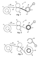
- the winding and unwinding mandrel operating in winding during the last pass is the first winding mandrel and unwinding 21 when the number of passes is even and the second mandrel winding and unwinding 22 when the number of passes is odd.
- a few turns 29 of the previously formed coil on the winding and unrolling device running during this penultimate pass are not unrolled so that during the last pass, the sheet of deformable material 27 is interposed between two adjacent turns of the coil 28 formed around the winding mandrel and unwinding running in winding during the last pass.
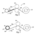
- the figure 8 represents a fourth mode of implementation of the method according to the invention.
- the unwound metal strip 36 can be shaped using different working tools 37, 38.
- the sheet of deformable material used in the various embodiments of the method according to the invention is made from a bubble film, and preferably a three-layer bubble film, at least one faces of said sheet having a coating arranged to promote its adhesion on the winding or unwinding mandrel or on the strip.
- the closed cells of the sheet of deformable material used in these different modes of operation enclose a gas, preferably air.
- the sheet of deformable material is advantageously made of polyethylene terephthalate.
Landscapes
- Engineering & Computer Science (AREA)
- Mechanical Engineering (AREA)
- Winding, Rewinding, Material Storage Devices (AREA)
- Winding Of Webs (AREA)
Claims (13)
- Schutzverfahren eines Bands (6, 26, 36) vorzugsweise aus Metall beim Aufrollen desselben als Rolle um eine Aufrollvorrichtung (3, 21) oder beim Abrollen desselben von einer Rolle (33), die um eine Abrollvorrichtung (31) angeordnet ist, das einen Schritt umfasst, der darin besteht, eine Bahn (9, 27, 32) aus verformbarem Material zwischen der Aufroll- oder der Abrollvorrichtung und dem Abschnitt des zu schützenden Bands zwischenzustellen, dadurch gekennzeichnet, dass die Bahn aus verformbarem Material eine Wabenstruktur mit geschlossenen Waben hat, die eine dreischichtige Luftpolsterfolie umfasst, wobei mindestens eine der Seiten der Bahn eine Beschichtung aufweist, die ausgebildet ist, um ihr Haften auf der Aufroll- oder Abrollvorrichtung oder auf dem Band zu fördern.
- Schutzverfahren nach Anspruch 1, dadurch gekennzeichnet, dass die verwendete Bahn (9, 27, 32) aus verformbarem Material eine Länge aufweist, die etwa dem Umfang der Aufroll- (3, 21) oder Abrollvorrichtung (31) entspricht.
- Schutzverfahren nach einem der Ansprüche 1 oder 2, dadurch gekennzeichnet, dass die geschlossenen Waben der verwendeten Bahn aus verformbarem Material ein Gas, vorzugsweise Luft, einschließen.
- Schutzverfahren nach einem der Ansprüche 1 bis 3, dadurch gekennzeichnet, dass die Bahn aus verformbarem Material aus einer Luftpolsterfolie durch Übereinanderlegen von zwei dreischichtigen Luftpolsterfolien hergestellt ist.
- Schutzverfahren nach einem der Ansprüche 1 bis 4, dadurch gekennzeichnet, dass es die Schritte umfasst, die darin bestehen, eine Bahn (32) aus verformbarem Material mit Wabenstruktur mit geschlossenen Waben um eine Abrollvorrichtung (31) zu positionieren, um die Abrollvorrichtung und die Bahn eine Rolle (33) anzuordnen, die eine Wicklung eines Bands (36) aufweist, und das Band von der Rolle abzurollen.
- Schutzverfahren nach einem der Ansprüche 1 bis 4, dadurch gekennzeichnet, dass es die Schritte umfasst, die darin bestehen, einen Abschnitt des Bands (9) um eine Aufrollvorrichtung (3) aufzurollen, die Bahn (9) aus verformbarem Material mit Wabenstruktur mit geschlossenen Waben auf dem nicht aufgerollten Abschnitt des Bands zu positionieren und den Rest des Bands um die Aufrollvorrichtung (3) aufzurollen, um eine Rolle zu bilden, wobei die Bahn aus verformbarem Material derart auf dem Band angeordnet ist, dass sie zwischen zwei benachbarten Lagen der Rolle zwischengestellt ist.
- Schutzverfahren nach einem der Ansprüche 1 bis 4, dadurch gekennzeichnet, dass es die Schritte umfasst, die darin bestehen, die Bahn (9) aus verformbarem Material mit Wabenstruktur mit geschlossenen Waben auf dem Band (6) zu positionieren und das Band um eine Aufrollvorrichtung (3) aufzurollen, um eine Rolle (12) zu bilden, wobei die Bahn aus verformbarem Material derart auf dem Band angeordnet ist, dass sie zwischen mindestens einem Abschnitt der ersten Lage der Rolle und der Aufrollvorrichtung zwischengestellt ist.
- Schutzverfahren nach Anspruch 7, dadurch gekennzeichnet, dass es einen Schritt umfasst, der vor dem Schritt der Positionierung der Bahn aus verformbarem Material auf dem Band durchgeführt wird und darin besteht, den Kopf des Bands auf der Aufrollvorrichtung (3) zu befestigen, und dass der Schritt der Positionierung der Bahn aus verformbarem Material auf dem Band darin besteht, die Bahn (9) auf dem Band derart zu positionieren, dass sich der Querrand der Bahn, der zur Seite der Aufrollvorrichtung zeigt, in der Nähe oder auf Ebene der Befestigungszone (A) des Bands auf der Aufrollvorrichtung befindet.
- Schutzverfahren nach einem der Ansprüche 1 bis 4, dadurch gekennzeichnet, dass es die Schritte umfasst, die bestehen in:a) der Bereitstellung einer ersten Aufroll- und Abrollvorrichtung (21), einer zweiten Aufroll- und Abrollvorrichtung (22) und von reversiblen Kaltwalzmitteln (23), die zwischen der ersten und zweiten Aufroll- und Abrollvorrichtung angeordnet sind,b) dem Abrollen eines Bands (26) von einer Rolle, die um die erste Aufroll- und Abrollvorrichtung (21) angeordnet ist, die abrollend arbeitet,c) dem Walzen des Bands (26) mit Hilfe der Kaltwalzmittel,d) dem Aufrollen des Bands um die zweite Aufroll- und Abrollvorrichtung (22), die aufrollend arbeitet, derart, dass eine Rolle gebildet wird, wobei die Schritte b) bis d) einen ersten Durchgang des Bands zwischen den Kaltwalzmitteln darstellen,e) dem Abrollen des Bands (26) von der Rolle, die sich um die zweite Aufroll- und Abrollvorrichtung (22), die abrollend arbeitet, gebildet hat,f) dem Walzen des Bands mit Hilfe der Kaltwalzmittel,g) dem Aufrollen des Bands um die erste Aufroll- und Abrollvorrichtung (21), die aufrollend arbeitet, derart, dass eine Rolle gebildet wird, wobei die Schritte e) bis g) einen zweiten Durchgang des Bands zwischen den Kaltwalzmitteln darstellen,h) der Wiederholung, sofern notwendig, der Schritte b) bis g) bis zum Erhalt der gewünschten Qualität des Bands,i) der Positionierung der Bahn (27) aus verformbarem Material mit Wabenstruktur mit geschlossenen Waben auf dem Band (26) in der Nähe der Aufroll- und Abrollvorrichtung (21), die beim letzten Durchgang aufrollend arbeitet, und vollständiges Aufrollen des Bands um die Aufroll- und Abrollvorrichtung (21), die aufrollend arbeitet, beim letzten Durchgang, um eine Rolle (28) zu bilden, zu Beginn des zweiten Durchgangs.
- Schutzverfahren nach Anspruch 9, dadurch gekennzeichnet, dass beim vorletzten Durchgang mindestens eine Lage (29) der zuvor auf der Aufroll- und Abrollvorrichtung (21), die bei diesem vorletzten Durchgang abrollend arbeitet, gebildeten Rolle nicht abgerollt wird, so dass beim letzten Durchgang die Bahn (27) aus verformbarem Material zwischen zwei benachbarten Lagen der Rolle (28) zwischengestellt ist.
- Gruppe für die Umsetzung des Verfahrens nach einem der Ansprüche 1 bis 5, dadurch gekennzeichnet, dass sie eine Abrollvorrichtung (31), eine Bahn (32) aus verformbarem Material mit Wabenstruktur mit geschlossenen Waben, die um die Abrollvorrichtung angeordnet ist, und eine Rolle (33), die um die Bahn aus verformbarem Material angeordnet ist, umfasst, wobei die Rolle eine Wicklung eines vorzugsweise metallischen Bands aufweist, wobei die Bahn aus verformbarem Material eine dreischichtige Luftpolsterfolie umfasst und wobei mindestens eine der Seiten der Bahn eine Beschichtung aufweist, die ausgebildet ist, um ihr Haften auf der Abrollvorrichtung oder auf dem Band zu fördern.
- Rolle, die durch die Umsetzung des Verfahrens nach einem der Ansprüche 1 bis 4 und 6 bis 10 hergestellt wird, dadurch gekennzeichnet, dass sie eine Wicklung eines vorzugsweise metallischen Bands und einer Bahn aus verformbarem Material mit Wabenstruktur mit geschlossenen Waben aufweist, wobei die Bahn aus verformbarem Material eine dreischichtige Luftpolsterfolie umfasst und wobei mindestens eine der Seiten der Bahn eine Beschichtung aufweist, die ausgebildet ist, um ihr Haften auf der Abrollvorrichtung oder auf dem Band zu fördern.
- Rolle nach Anspruch 12, dadurch gekennzeichnet, dass die Bahn aus verformbarem Material mit Wabenstruktur mit geschlossenen Waben zwischen zwei benachbarten Lagen der Rolle zwischengestellt ist oder mindestens teilweise die erste Lage der Rolle bildet.
Applications Claiming Priority (1)
| Application Number | Priority Date | Filing Date | Title |
|---|---|---|---|
| FR0806500A FR2938517B1 (fr) | 2008-11-20 | 2008-11-20 | Procede de protection d'une bande lors de son enroulement en bobine ou de son deroulement a partir d'une bobine |
Publications (2)
| Publication Number | Publication Date |
|---|---|
| EP2189228A1 EP2189228A1 (de) | 2010-05-26 |
| EP2189228B1 true EP2189228B1 (de) | 2013-01-16 |
Family
ID=40834429
Family Applications (1)
| Application Number | Title | Priority Date | Filing Date |
|---|---|---|---|
| EP20090176483 Not-in-force EP2189228B1 (de) | 2008-11-20 | 2009-11-19 | Verfahren zum Schützen eines Bandes während des Aufwickelns zu oder Abwickelns von einer Spule |
Country Status (2)
| Country | Link |
|---|---|
| EP (1) | EP2189228B1 (de) |
| FR (1) | FR2938517B1 (de) |
Families Citing this family (1)
| Publication number | Priority date | Publication date | Assignee | Title |
|---|---|---|---|---|
| CN102847749A (zh) * | 2011-06-29 | 2013-01-02 | 鞍钢股份有限公司 | 一种卷取机卷筒钳口定位方法 |
Family Cites Families (2)
| Publication number | Priority date | Publication date | Assignee | Title |
|---|---|---|---|---|
| GB1135870A (en) * | 1966-06-03 | 1968-12-04 | Canadian Ind | Method of winding thermoplastic resin sheeting into rolls and rolls obtained thereby |
| US3396918A (en) * | 1967-01-09 | 1968-08-13 | Goodyear Tire & Rubber | Expandable adapter |
-
2008
- 2008-11-20 FR FR0806500A patent/FR2938517B1/fr not_active Expired - Fee Related
-
2009
- 2009-11-19 EP EP20090176483 patent/EP2189228B1/de not_active Not-in-force
Also Published As
| Publication number | Publication date |
|---|---|
| EP2189228A1 (de) | 2010-05-26 |
| FR2938517A1 (fr) | 2010-05-21 |
| FR2938517B1 (fr) | 2011-03-04 |
Similar Documents
| Publication | Publication Date | Title |
|---|---|---|
| US8360223B2 (en) | Medium storing and advancing apparatus | |
| KR20020085834A (ko) | 롤 제품 및 그 권취 방법 | |
| US11858767B2 (en) | Methods and apparatus for a turn-up procedure using an adhesive paperband composite | |
| EP2189228B1 (de) | Verfahren zum Schützen eines Bandes während des Aufwickelns zu oder Abwickelns von einer Spule | |
| CA2817406A1 (en) | Improvement in rolled sheets of floor covering and manufacture | |
| EP2017205B1 (de) | Verfahren zur Herstellung einer Rolle mit Mitten-Abreißanschlag | |
| FR2763321A1 (fr) | Machine pour bobiner du film, procede de fabrication de bobines de films pre-etires et bobines de films pre-etires obtenues par ledit procede | |
| JP3490637B2 (ja) | 材料ラップロール、該材料ラップロールを製造する方法および該方法を実施するための装置 | |
| EP2122100B1 (de) | Verfahren zur herstellung eines rollladens und verfahren zur herstellung einer einheit aus zwei zahnriemen | |
| EP0935505B1 (de) | Wickelmaschine | |
| FI127183B (fi) | Kartonkia oleva rullausydin epäorgaanisia materiaaleja varten, jossa on irrotettava päällikerros | |
| CA2759097A1 (en) | Wrapper for metal coils | |
| US20050258299A1 (en) | Core for aluminum sheet | |
| EP1747158B1 (de) | Verfahren zur herstellung einer zentralen abwickelrolle und rolle | |
| EP1295828A1 (de) | Bandförmiger Träger für Klebeetiketten | |
| FR2581633A1 (fr) | Mandrin pour bobineau de film presentant une adherence de surface | |
| EP0089251A1 (de) | Verfahren zum Verpacken einer Spule mittels eines Bandeisens | |
| EP0798682B1 (de) | Verfahren zum Anbringen eines metallischen Drahtes oder Bandes auf einem dünnen Blatt und Rolle von diesem Blatt | |
| EP0202983B1 (de) | Verfahren und Apparat zur Herstellung einer thermischen mehrschichtigen Isolierung rundum und entlang einer festen Durchfuhr und dazugehöriger Kryogenbehälter | |
| FR2703030A1 (fr) | Conditionnement pour fil, câble ou analogue. | |
| FR2906527A1 (fr) | Dispositif de retrait d'une pellicule. | |
| EP0820930B1 (de) | Umreifungsmaschine für Bandmaterialrollen | |
| FR2887535A1 (fr) | Dispositif pour annuler la torsion d'un lien entre une extremite fixe et une extremite tournante | |
| WO1998050226A1 (fr) | Carton ondule rigide | |
| JPH05229085A (ja) | ストリップにライニングを被覆する方法および装置 |
Legal Events
| Date | Code | Title | Description |
|---|---|---|---|
| PUAI | Public reference made under article 153(3) epc to a published international application that has entered the european phase |
Free format text: ORIGINAL CODE: 0009012 |
|
| AK | Designated contracting states |
Kind code of ref document: A1 Designated state(s): AT BE BG CH CY CZ DE DK EE ES FI FR GB GR HR HU IE IS IT LI LT LU LV MC MK MT NL NO PL PT RO SE SI SK SM TR |
|
| AX | Request for extension of the european patent |
Extension state: AL BA RS |
|
| 17P | Request for examination filed |
Effective date: 20101126 |
|
| RIC1 | Information provided on ipc code assigned before grant |
Ipc: B21C 47/02 20060101ALI20120802BHEP Ipc: B21C 47/16 20060101ALI20120802BHEP Ipc: B21C 47/34 20060101ALI20120802BHEP Ipc: B21C 47/00 20060101AFI20120802BHEP |
|
| GRAP | Despatch of communication of intention to grant a patent |
Free format text: ORIGINAL CODE: EPIDOSNIGR1 |
|
| GRAS | Grant fee paid |
Free format text: ORIGINAL CODE: EPIDOSNIGR3 |
|
| GRAA | (expected) grant |
Free format text: ORIGINAL CODE: 0009210 |
|
| AK | Designated contracting states |
Kind code of ref document: B1 Designated state(s): AT BE BG CH CY CZ DE DK EE ES FI FR GB GR HR HU IE IS IT LI LT LU LV MC MK MT NL NO PL PT RO SE SI SK SM TR |
|
| REG | Reference to a national code |
Ref country code: GB Ref legal event code: FG4D Free format text: NOT ENGLISH |
|
| REG | Reference to a national code |
Ref country code: CH Ref legal event code: EP |
|
| REG | Reference to a national code |
Ref country code: IE Ref legal event code: FG4D Free format text: LANGUAGE OF EP DOCUMENT: FRENCH |
|
| REG | Reference to a national code |
Ref country code: AT Ref legal event code: REF Ref document number: 593587 Country of ref document: AT Kind code of ref document: T Effective date: 20130215 Ref country code: CH Ref legal event code: EP |
|
| REG | Reference to a national code |
Ref country code: DE Ref legal event code: R096 Ref document number: 602009012788 Country of ref document: DE Effective date: 20130321 |
|
| REG | Reference to a national code |
Ref country code: AT Ref legal event code: MK05 Ref document number: 593587 Country of ref document: AT Kind code of ref document: T Effective date: 20130116 |
|
| REG | Reference to a national code |
Ref country code: NL Ref legal event code: VDEP Effective date: 20130116 |
|
| REG | Reference to a national code |
Ref country code: LT Ref legal event code: MG4D |
|
| PG25 | Lapsed in a contracting state [announced via postgrant information from national office to epo] |
Ref country code: BG Free format text: LAPSE BECAUSE OF FAILURE TO SUBMIT A TRANSLATION OF THE DESCRIPTION OR TO PAY THE FEE WITHIN THE PRESCRIBED TIME-LIMIT Effective date: 20130416 Ref country code: LT Free format text: LAPSE BECAUSE OF FAILURE TO SUBMIT A TRANSLATION OF THE DESCRIPTION OR TO PAY THE FEE WITHIN THE PRESCRIBED TIME-LIMIT Effective date: 20130116 Ref country code: ES Free format text: LAPSE BECAUSE OF FAILURE TO SUBMIT A TRANSLATION OF THE DESCRIPTION OR TO PAY THE FEE WITHIN THE PRESCRIBED TIME-LIMIT Effective date: 20130427 Ref country code: AT Free format text: LAPSE BECAUSE OF FAILURE TO SUBMIT A TRANSLATION OF THE DESCRIPTION OR TO PAY THE FEE WITHIN THE PRESCRIBED TIME-LIMIT Effective date: 20130116 Ref country code: SE Free format text: LAPSE BECAUSE OF FAILURE TO SUBMIT A TRANSLATION OF THE DESCRIPTION OR TO PAY THE FEE WITHIN THE PRESCRIBED TIME-LIMIT Effective date: 20130116 Ref country code: NO Free format text: LAPSE BECAUSE OF FAILURE TO SUBMIT A TRANSLATION OF THE DESCRIPTION OR TO PAY THE FEE WITHIN THE PRESCRIBED TIME-LIMIT Effective date: 20130416 Ref country code: IS Free format text: LAPSE BECAUSE OF FAILURE TO SUBMIT A TRANSLATION OF THE DESCRIPTION OR TO PAY THE FEE WITHIN THE PRESCRIBED TIME-LIMIT Effective date: 20130516 |
|
| PG25 | Lapsed in a contracting state [announced via postgrant information from national office to epo] |
Ref country code: GR Free format text: LAPSE BECAUSE OF FAILURE TO SUBMIT A TRANSLATION OF THE DESCRIPTION OR TO PAY THE FEE WITHIN THE PRESCRIBED TIME-LIMIT Effective date: 20130417 Ref country code: NL Free format text: LAPSE BECAUSE OF FAILURE TO SUBMIT A TRANSLATION OF THE DESCRIPTION OR TO PAY THE FEE WITHIN THE PRESCRIBED TIME-LIMIT Effective date: 20130116 Ref country code: PT Free format text: LAPSE BECAUSE OF FAILURE TO SUBMIT A TRANSLATION OF THE DESCRIPTION OR TO PAY THE FEE WITHIN THE PRESCRIBED TIME-LIMIT Effective date: 20130516 Ref country code: LV Free format text: LAPSE BECAUSE OF FAILURE TO SUBMIT A TRANSLATION OF THE DESCRIPTION OR TO PAY THE FEE WITHIN THE PRESCRIBED TIME-LIMIT Effective date: 20130116 Ref country code: FI Free format text: LAPSE BECAUSE OF FAILURE TO SUBMIT A TRANSLATION OF THE DESCRIPTION OR TO PAY THE FEE WITHIN THE PRESCRIBED TIME-LIMIT Effective date: 20130116 Ref country code: SI Free format text: LAPSE BECAUSE OF FAILURE TO SUBMIT A TRANSLATION OF THE DESCRIPTION OR TO PAY THE FEE WITHIN THE PRESCRIBED TIME-LIMIT Effective date: 20130116 Ref country code: PL Free format text: LAPSE BECAUSE OF FAILURE TO SUBMIT A TRANSLATION OF THE DESCRIPTION OR TO PAY THE FEE WITHIN THE PRESCRIBED TIME-LIMIT Effective date: 20130116 |
|
| PG25 | Lapsed in a contracting state [announced via postgrant information from national office to epo] |
Ref country code: HR Free format text: LAPSE BECAUSE OF FAILURE TO SUBMIT A TRANSLATION OF THE DESCRIPTION OR TO PAY THE FEE WITHIN THE PRESCRIBED TIME-LIMIT Effective date: 20130116 |
|
| PG25 | Lapsed in a contracting state [announced via postgrant information from national office to epo] |
Ref country code: RO Free format text: LAPSE BECAUSE OF FAILURE TO SUBMIT A TRANSLATION OF THE DESCRIPTION OR TO PAY THE FEE WITHIN THE PRESCRIBED TIME-LIMIT Effective date: 20130116 Ref country code: CZ Free format text: LAPSE BECAUSE OF FAILURE TO SUBMIT A TRANSLATION OF THE DESCRIPTION OR TO PAY THE FEE WITHIN THE PRESCRIBED TIME-LIMIT Effective date: 20130116 Ref country code: SK Free format text: LAPSE BECAUSE OF FAILURE TO SUBMIT A TRANSLATION OF THE DESCRIPTION OR TO PAY THE FEE WITHIN THE PRESCRIBED TIME-LIMIT Effective date: 20130116 Ref country code: DK Free format text: LAPSE BECAUSE OF FAILURE TO SUBMIT A TRANSLATION OF THE DESCRIPTION OR TO PAY THE FEE WITHIN THE PRESCRIBED TIME-LIMIT Effective date: 20130116 Ref country code: EE Free format text: LAPSE BECAUSE OF FAILURE TO SUBMIT A TRANSLATION OF THE DESCRIPTION OR TO PAY THE FEE WITHIN THE PRESCRIBED TIME-LIMIT Effective date: 20130116 |
|
| PLBE | No opposition filed within time limit |
Free format text: ORIGINAL CODE: 0009261 |
|
| STAA | Information on the status of an ep patent application or granted ep patent |
Free format text: STATUS: NO OPPOSITION FILED WITHIN TIME LIMIT |
|
| PG25 | Lapsed in a contracting state [announced via postgrant information from national office to epo] |
Ref country code: CY Free format text: LAPSE BECAUSE OF FAILURE TO SUBMIT A TRANSLATION OF THE DESCRIPTION OR TO PAY THE FEE WITHIN THE PRESCRIBED TIME-LIMIT Effective date: 20130116 |
|
| 26N | No opposition filed |
Effective date: 20131017 |
|
| PG25 | Lapsed in a contracting state [announced via postgrant information from national office to epo] |
Ref country code: IT Free format text: LAPSE BECAUSE OF FAILURE TO SUBMIT A TRANSLATION OF THE DESCRIPTION OR TO PAY THE FEE WITHIN THE PRESCRIBED TIME-LIMIT Effective date: 20130116 |
|
| REG | Reference to a national code |
Ref country code: DE Ref legal event code: R097 Ref document number: 602009012788 Country of ref document: DE Effective date: 20131017 |
|
| BERE | Be: lapsed |
Owner name: JLL ENGINEERING Effective date: 20131130 |
|
| REG | Reference to a national code |
Ref country code: CH Ref legal event code: PL |
|
| GBPC | Gb: european patent ceased through non-payment of renewal fee |
Effective date: 20131119 |
|
| PG25 | Lapsed in a contracting state [announced via postgrant information from national office to epo] |
Ref country code: CH Free format text: LAPSE BECAUSE OF NON-PAYMENT OF DUE FEES Effective date: 20131130 Ref country code: MC Free format text: LAPSE BECAUSE OF FAILURE TO SUBMIT A TRANSLATION OF THE DESCRIPTION OR TO PAY THE FEE WITHIN THE PRESCRIBED TIME-LIMIT Effective date: 20130116 Ref country code: LI Free format text: LAPSE BECAUSE OF NON-PAYMENT OF DUE FEES Effective date: 20131130 |
|
| REG | Reference to a national code |
Ref country code: IE Ref legal event code: MM4A |
|
| PG25 | Lapsed in a contracting state [announced via postgrant information from national office to epo] |
Ref country code: BE Free format text: LAPSE BECAUSE OF NON-PAYMENT OF DUE FEES Effective date: 20131130 |
|
| PG25 | Lapsed in a contracting state [announced via postgrant information from national office to epo] |
Ref country code: IE Free format text: LAPSE BECAUSE OF NON-PAYMENT OF DUE FEES Effective date: 20131119 |
|
| PG25 | Lapsed in a contracting state [announced via postgrant information from national office to epo] |
Ref country code: GB Free format text: LAPSE BECAUSE OF NON-PAYMENT OF DUE FEES Effective date: 20131119 |
|
| PGFP | Annual fee paid to national office [announced via postgrant information from national office to epo] |
Ref country code: DE Payment date: 20141117 Year of fee payment: 6 |
|
| PG25 | Lapsed in a contracting state [announced via postgrant information from national office to epo] |
Ref country code: SM Free format text: LAPSE BECAUSE OF FAILURE TO SUBMIT A TRANSLATION OF THE DESCRIPTION OR TO PAY THE FEE WITHIN THE PRESCRIBED TIME-LIMIT Effective date: 20130116 |
|
| PG25 | Lapsed in a contracting state [announced via postgrant information from national office to epo] |
Ref country code: TR Free format text: LAPSE BECAUSE OF FAILURE TO SUBMIT A TRANSLATION OF THE DESCRIPTION OR TO PAY THE FEE WITHIN THE PRESCRIBED TIME-LIMIT Effective date: 20130116 |
|
| PG25 | Lapsed in a contracting state [announced via postgrant information from national office to epo] |
Ref country code: MK Free format text: LAPSE BECAUSE OF FAILURE TO SUBMIT A TRANSLATION OF THE DESCRIPTION OR TO PAY THE FEE WITHIN THE PRESCRIBED TIME-LIMIT Effective date: 20130116 Ref country code: LU Free format text: LAPSE BECAUSE OF NON-PAYMENT OF DUE FEES Effective date: 20131119 Ref country code: HU Free format text: LAPSE BECAUSE OF FAILURE TO SUBMIT A TRANSLATION OF THE DESCRIPTION OR TO PAY THE FEE WITHIN THE PRESCRIBED TIME-LIMIT; INVALID AB INITIO Effective date: 20091119 |
|
| PG25 | Lapsed in a contracting state [announced via postgrant information from national office to epo] |
Ref country code: MT Free format text: LAPSE BECAUSE OF FAILURE TO SUBMIT A TRANSLATION OF THE DESCRIPTION OR TO PAY THE FEE WITHIN THE PRESCRIBED TIME-LIMIT Effective date: 20130116 |
|
| REG | Reference to a national code |
Ref country code: FR Ref legal event code: PLFP Year of fee payment: 7 |
|
| REG | Reference to a national code |
Ref country code: DE Ref legal event code: R119 Ref document number: 602009012788 Country of ref document: DE |
|
| REG | Reference to a national code |
Ref country code: FR Ref legal event code: PLFP Year of fee payment: 8 |
|
| PG25 | Lapsed in a contracting state [announced via postgrant information from national office to epo] |
Ref country code: DE Free format text: LAPSE BECAUSE OF NON-PAYMENT OF DUE FEES Effective date: 20160601 |
|
| REG | Reference to a national code |
Ref country code: FR Ref legal event code: PLFP Year of fee payment: 9 |
|
| REG | Reference to a national code |
Ref country code: FR Ref legal event code: PLFP Year of fee payment: 10 |
|
| PGFP | Annual fee paid to national office [announced via postgrant information from national office to epo] |
Ref country code: FR Payment date: 20191017 Year of fee payment: 11 |
|
| PG25 | Lapsed in a contracting state [announced via postgrant information from national office to epo] |
Ref country code: FR Free format text: LAPSE BECAUSE OF NON-PAYMENT OF DUE FEES Effective date: 20201130 |