EP2189255B1 - Dispositif d'assistance et son procédé de commande - Google Patents
Dispositif d'assistance et son procédé de commande Download PDFInfo
- Publication number
- EP2189255B1 EP2189255B1 EP08830123.9A EP08830123A EP2189255B1 EP 2189255 B1 EP2189255 B1 EP 2189255B1 EP 08830123 A EP08830123 A EP 08830123A EP 2189255 B1 EP2189255 B1 EP 2189255B1
- Authority
- EP
- European Patent Office
- Prior art keywords
- external force
- force
- along
- component
- speed
- Prior art date
- Legal status (The legal status is an assumption and is not a legal conclusion. Google has not performed a legal analysis and makes no representation as to the accuracy of the status listed.)
- Not-in-force
Links
Images



Classifications
-
- G—PHYSICS
- G05—CONTROLLING; REGULATING
- G05B—CONTROL OR REGULATING SYSTEMS IN GENERAL; FUNCTIONAL ELEMENTS OF SUCH SYSTEMS; MONITORING OR TESTING ARRANGEMENTS FOR SUCH SYSTEMS OR ELEMENTS
- G05B19/00—Program-control systems
- G05B19/02—Program-control systems electric
- G05B19/42—Recording and playback systems, i.e. in which the program is recorded from a cycle of operations, e.g. the cycle of operations being manually controlled, after which this record is played back on the same machine
- G05B19/423—Teaching successive positions by walk-through, i.e. the tool head or end effector being grasped and guided directly, with or without servo-assistance, to follow a path
-
- B—PERFORMING OPERATIONS; TRANSPORTING
- B25—HAND TOOLS; PORTABLE POWER-DRIVEN TOOLS; MANIPULATORS
- B25J—MANIPULATORS; CHAMBERS PROVIDED WITH MANIPULATION DEVICES
- B25J13/00—Controls for manipulators
- B25J13/02—Hand grip control means
- B25J13/025—Hand grip control means comprising haptic means
-
- G—PHYSICS
- G05—CONTROLLING; REGULATING
- G05B—CONTROL OR REGULATING SYSTEMS IN GENERAL; FUNCTIONAL ELEMENTS OF SUCH SYSTEMS; MONITORING OR TESTING ARRANGEMENTS FOR SUCH SYSTEMS OR ELEMENTS
- G05B2219/00—Program-control systems
- G05B2219/30—Nc systems
- G05B2219/36—Nc in input of data, input key till input tape
- G05B2219/36429—Power assisted positioning
-
- G—PHYSICS
- G05—CONTROLLING; REGULATING
- G05B—CONTROL OR REGULATING SYSTEMS IN GENERAL; FUNCTIONAL ELEMENTS OF SUCH SYSTEMS; MONITORING OR TESTING ARRANGEMENTS FOR SUCH SYSTEMS OR ELEMENTS
- G05B2219/00—Program-control systems
- G05B2219/30—Nc systems
- G05B2219/39—Robotics, robotics to robotics hand
- G05B2219/39339—Admittance control, admittance is tip speed-force
Definitions
- the present invention relates to a power assist device and its control method.
- a robot referred to as a power assist device is used so as to reduce labor and improve workability.
- a control method of the power assist device mechanical impedance control based on a position control (called an admittance control) is widely adopted.
- the position control with high gain is performed and its target position is determined based on a force sensor. Then, force applied on the power assist device not through the force sensor is not considered at the control action, and a manipulator is hardly actuated. Namely, when the power assist device is brought into contact with an environment (the external) at the position except the detection part of the force sensor, the power assist device is continued to be actuated without consideration of the contact.
- the Non-patent Literature 1 shown below discloses a method of the admittance control with consideration of connection with an environment by using estimated value of external force acting on the power assist device not via any force sensor.
- An assist transportation system device capable of properly communicating a reaction force to a worker due to contact without damaging any product and obstacle is known from US 2007/0112458 A1 .
- the worker operates transportation means to transport a product, in which the product contacts with an obstacle, the product is floated from the transportation means to moderate the impact, the displacement value of the product die to floating is detected, the displacement value is processed to compute a reaction force due to the impact, and the reaction force is communicated to the worker.
- Non-patent Literature 1 Masahito Iso, Hirokazu Seki, and Yoichi Hori, Sensorless power assist method using impedance control considering load characteristics, Technical Meeting on Industrial Instrumentation and Control, IEE Japan, Vol. IIC-02-40 (2002 )
- the purpose of the present invention is to provide a power assist device which can maintain a stable contact state without causing an oscillation phenomenon even if a robot is brought into contact with an environment, and to provide a method for controlling the power assist device.
- the first aspect of the present invention is a power assist device which includes an operation part operated by an operator; an operation force detection means for detecting operation force applied on the operation part; a robot arm for supporting the operation part; a drive means for driving the robot arm; an external force measurement means for measuring force applied when the robot arm is brought into contact with an environment, or an external force estimation means for estimating force applied when the robot arm is brought into contact with the environment; and a speed detection means for detecting movement speed of the operation part, or a speed estimation means for estimating the movement speed of the operation part, wherein a control device is provided that obtains corrected external force based on the external force obtained by the external force measurement means or the external force estimation means and a component along the external force of the operation force detected by the operation force detection means, and controls the drive means so as to maintain the state that the operation force and the corrected external force act on the operation part and the component along the external force of the operation force and the corrected external force acting on the robot arm are always balanced with each other.
- the control device compares the component along the external force of the operation force detected by the operation force detection means with the external force obtained by the external force measurement means or the external force estimation means, regards the speed of the operation part calculated from the external force as speed of the operation part along the external force calculated from the component along the external force of the operation force so as to obtain the corrected external force when the component along the external force of the operation force is opposite to the external force and the external force is larger than the component along the external force of the operation force, and adopts the external force without any operation as the corrected external force when the component along the external force of the operation force has the same direction as the external force or the external force is smaller than the component along the external force of the operation force.
- the control device compares the component along the external force of the operation force detected by the operation force detection means with the external force obtained by the external force measurement means or the external force estimation means, regards the external force as a component of the operation force along the external force so as to obtain the corrected external force when the component along the external force of the operation force is opposite to the external force and the external force is larger than the component along the external force of the operation force, and adopts the external force without any operation as the corrected external force when the component along the external force of the operation force has the same direction as the external force or the external force is smaller than the component along the external force of the operation force.
- the second aspect of the present invention is a control method of a power assist device which includes an operation part operated by an operator; an operation force detection means for detecting operation force applied on the operation part; a robot arm for supporting the operation part; a drive means for driving the robot arm; an external force measurement means for measuring force applied when the robot arm is brought into contact with an environment, or an external force estimation means for estimating force applied when the robot arm is brought into contact with the environment; and a speed detection means for detecting movement speed of the operation part, or a speed estimation means for estimating the movement speed of the operation part, wherein corrected external force is obtained based on the external force obtained by the external force measurement means or the external force estimation means and a component along the external force of the operation force detected by the operation force detection means, and the drive means is controlled so as to maintain the state that the operation force and the corrected external force act on the operation part and the component along the external force of the operation force and the corrected external force acting on the robot arm are always balanced with each other.
- the speed along the external force of the operation part calculated from the component along the external force of the operation force detected by the operation force detection means is compared with the speed of the operation part calculated from the external force obtained by the external force measurement means or the external force estimation means, the speed of the operation part calculated from the external force is regarded as the speed along the external force of the operation part calculated from the component along the external force of the operation force so as to obtained the corrected external force when the speed along the external force of the operation part calculated from the component along the external force of the operation force is opposite to the speed of the operation part calculated from the external force and the speed of the operation part calculated from the external force is larger than the speed along the external force of the operation part calculated from the component along the external force of the operation force, and the external force without any operation is adopted as the corrected external force when the speed along the external force of the operation part calculated from the component along the external force of the operation force has the same direction as the speed of the operation part calculated from the external force or the speed of the operation part calculated from the external force
- the component along the external force of the operation force detected by the operation force detection means is compared with the external force obtained by the external force measurement means or the external force estimation means, the external force is regarded as a component of the operation force along the external force so as to obtain the corrected external force when the component along the external force of the operation force is opposite to the external force and the external force is larger than the component along the external force of the operation force, and the external force without any operation is adopted as the corrected external force when the component along the external force of the operation force has the same direction as the external force or the external force is smaller than the component along the external force of the operation force.
- the oscillation phenomenon is prevented and the stable connection state is maintained.
- the external force is corrected to be limited so as to suppress the oscillation phenomenon on the power assist device without spoiling the operability.
- the oscillation phenomenon on the power assist device is suppressed more certainly without spoiling the operability.
- the control method of the power assist device of the present invention when the power assist device is brought into contact with the environment, the oscillation phenomenon is prevented and the stable connection state is maintained.
- the external force is corrected to be limited so as to suppress the oscillation phenomenon on the power assist device without spoiling the operability.
- the oscillation phenomenon on the power assist device is suppressed more certainly without spoiling the operability.
- the power assist device 1 includes a robot arm 2, an inner force sensor 3, an operation handle 4, an actuator 5, a control device 6 and the like.
- the robot arm 2 is supported by the actuator 5 which is a drive means, and the robot device can assume various postures by the actuation of the actuator 5 following commands from the control device 6.
- the operation handle 4 which is an operation part is disposed at the tip of the robot arm 2 through the inner force sensor 3 which is an operation force detection means, and an operator can moves the robot arm 2 to a desired position by holding the operation handle 4.
- the operation force applied on the operation handle 4 by the operator at the time of the movement is detected by the inner force sensor 3.
- the actuator 5 can not only support and drive the robot arm 2 but also detect the posture of the robot arm 2 and detect the operation speed of the operation handle 4 as an operation speed detection means.
- the control device 6 which acts as an external force estimation means and an operation speed estimation means estimates external force (contact force) applied on the robot arm 2 by an environment.
- estimated value estimated by the control device 6 is adopted as the external force applied by the environment, it may alternatively be constructed that a force sensor which is an external force measurement means for connection detection is provided separately and actual measurement value is adopted as the external force applied by the environment.
- operation force f h by an operator and external force f e by the obstacle 7 act on the robot arm 2.
- the operation force f h and the external force f e are detected or estimated, and based on the detected values or estimated values, target tip position x dm at which desired impedance is realized is calculated by the control device 6.
- the control device 6 controls the actuator 5 for driving the robot arm 2 so as to move tip position x d of the robot arm 2 to the target tip position x dm .
- the resultant of the plurality of force must be "zero" and balanced so as to set the target tip position x dm to a fixed value.
- Delay of force detection by the inner force sensor 3 delay caused by time for calculation must be considered so as to obtain the target tip position x dm , set to a fixed value, by the control device 6.
- a control method that the external force f e used in the calculation with the formula 1 is corrected corresponding to the state of the operation force f h and the external force f e so as to prevent an oscillation phenomenon from being caused on the power assist device 1. Explanation will be given on the concrete control method.
- V d x ⁇ d
- T indicates sampling time
- the next target tip position x dm of the operation part is obtained from the operation force f h and the corrected external force f es , and the operation force f h and the corrected external force f es are maintained to be balanced with each other, whereby the calculation result of the target tip position x dm is not oscillated and the stable connection state is maintained.
- the control device 6 judges conditions (S03-1 and S03-2), and the control flow advances to a step (S04) in the case that both the steps (S03-1) and (S03-2) are satisfied and the control flow advances to a step (S05) in the other cases.
- the external force f e is corrected to the corrected external force f es so as to make the next target speed "zero". Since the speed V d at the time that the robot arm 2 is brought into contact with the environment is about "zero", the above control can be regarded that the external force f e is limited to the corrected external force f es so as to prevent vibration of the robot arm 2.
- the external force f e is adopted as the corrected external force f es without any operation.
- the control device 6 Based on the corrected external force f es obtained at the step (S04) or (S05), the control device 6 calculates target acceleration A d (S06), and the obtained target acceleration A d is temporally integrated so as to calculate the target speed V d and the target tip position x dm (S07), and then the control device 6 controls the drive of the actuator 5, which supports the robot arm 2, so as to materialize the target speed V d and the target tip position x dm .
- Each of calculating processes shown in Fig. 2 is performed by the control device 6.
- the target acceleration A d is obtained with below formula 4.
- a d f h + f es - D ⁇ V d / M
- the power assist device 1 includes: the inner force sensor 3 which detects the operation force applied by an operator; the operation handle 4 having the inner force sensor 3; the robot arm 2 which supports the operation handle 4; the actuator 5 which drives the robot arm 2; the actuator 5 and the control device 6 which measure or estimate the force applied when the robot arm 2 is brought into contact with an environment; and the actuator 5 and the control device 6 which detect or estimate the movement speed of the operation handle 4.
- the corrected external force f es is obtained based on the operation force f h detected by the inner force sensor 3 and the external force f e obtained by the actuator 5 and the control device 6, and the actuator 5 is controlled so that the corrected external force f es acts on the operation handle 4.
- the operation force f h detected by the inner force sensor 3 is compared with the external force f e obtained by the actuator 5 and the control device 6.
- the external force f e is limited to be not larger than the operation force f h so as to obtain the corrected external force f es
- the external force f e is adopted without any operation so as to obtain the corrected external force f es .
- the external force f e is corrected to be limited so as to suppress the oscillation phenomenon on the power assist device 1 without spoiling the operability.
- the external force f e is limited to make the speed calculated from the operation force f h and the external force f e "zero" so as to obtain the corrected external force f es , and when the external force f e is smaller than the predetermined threshold or has the same direction as the operation force f h , the external force f e is adopted without any operation as the corrected external force f es .
- the threshold so as to provide a dead band in the control action, the oscillation phenomenon on the power assist device 1 is suppressed more certainly without spoiling the operability.
- control method of the power assist device according to the embodiment of the present invention is not limited to be adopted to a one-dimensional model and is adoptable to a multidimensional model.
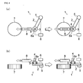
- the speed vector V a by the operation force obtained with the formula 2 can be indicated as Fig. 3(b) by dividing it into components (V 1 , V 2 ) of the direction of the speed vector Tf e /M obtained from the external force and the direction perpendicular thereto.
- the movement direction finally obtained from the operation force and the corrected external force is V k . Namely, any force does not act along the direction of the external force from the environment so that the oscillation is prevented.
- the operation force applied along a tangent of the environment (that is, the operation of moving the power assist device along the tangent of the outer edge of the environment) is not prevented.
- the inner force sensor 3 is disposed at the tip position of the robot arm 2
- the operation handle 4 is disposed at the tip position of the robot arm 2 through the inner force sensor 3.
- An experimental device is constructed that a hook 8a of a spring balance 8 is hanged on the operation handle 4 and an operator pulls the operation handle 4 via the spring balance 8 so as to displace the robot arm 2.
- the robot arm 2 When the operator pulls the operation handle 4 via the spring balance 8, the robot arm 2 is brought into contact with the environment (the obstacle 7), and the inner force sensor 3 detects the operation force f h at the time of the contact of the robot arm 2 with the obstacle 7.
- the estimated external force f e by the contact and the tip position x d are obtained by calculation based on information of position obtained from the actuator 5 driving the robot arm 2 and the like.
- Figs. 5(a), (b) and (c) The experimental results with the above experimental device are shown in Figs. 5(a), (b) and (c) .
- the axis of abscissas indicates time (s)
- a dotted line shown at the position just after the time 9 (s) in the graph indicates the timing of the contact of the robot arm 2 with the environment (the obstacle 7).
- the estimated external force f e by the contact which is not used for the control changes widely so that it is obtained that the robot arm 2 may break the environment in this control method.
- Fig. 5(c) shows the experimental result of the admittance control according to the present invention (namely, the robot arm 2 is assist-controlled with the information of the external force f e corrected corresponding to the operation force f h (the corrected external force f es )).
- the tip position x d does not oscillate and is stable at a fixed position from the time at which the robot arm 2 is brought into contact with the environment (the obstacle 7) to the time at which the robot arm 2 reaches the pressing state, whereby it is confirmed that the stable contact state is maintained.
- the control method of the power assist device according to the embodiment of the present invention, even if the robot is in contact with the environment, the oscillation phenomenon does not occur on the power assist device, whereby the power assist device can be provided that the stable contact state is maintained at the pressing work.
- the power assist device and the control method thereof according to the present invention can be used not only for a power assist device provided in an assembly line of a motorcar or the like but also for various uses widely in which a power assist device is used.
Landscapes
- Engineering & Computer Science (AREA)
- Robotics (AREA)
- Physics & Mathematics (AREA)
- General Physics & Mathematics (AREA)
- Automation & Control Theory (AREA)
- Human Computer Interaction (AREA)
- Mechanical Engineering (AREA)
- Manipulator (AREA)
Claims (4)
- Dispositif d'assistance (1) comprenant :une pièce de manoeuvre (4) manoeuvrée par un opérateur ;un moyen (3) de détection de force de manoeuvre destiné à détecter une force de manoeuvre (fh) appliquée à la pièce de manoeuvre (4) ;un bras de robot (2) destiné à supporter la pièce de manoeuvre (4) ;un moyen (5) d'entraînement destiné à entraîner le bras de robot (2) ;un moyen (5, 6) de mesure de force externe destiné à mesurer une force (fe) appliquée lorsque le bras de robot (2) est amené en contact avec un environnement (7), ou un moyen (5, 6) d'estimation de force externe destiné à estimer la force (fe) appliquée lorsque le bras de robot (2) est amené en contact avec l'environnement (7) ; etun moyen (5, 6) de détection de vitesse destiné à détecter la vitesse de déplacement (Va) de la pièce de manoeuvre (4), ou un moyen (5, 6) d'estimation de vitesse destiné à estimer la vitesse de déplacement (Va) de la pièce de manoeuvre (4),dans lequel il est prévu un dispositif de commande (6) qui obtient une force externe corrigée (fes) en se basant sur la force externe (fe) obtenue par le moyen (5, 6) de mesure de force externe ou par le moyen (5, 6) d'estimation de force externe et sur une composante de la force de manoeuvre (fh) suivant la force externe (fe) détectée par le moyen (3) de détection de force de manoeuvre, qui commande le moyen (5) d'entraînement de façon à maintenir un état dans lequel la force de manoeuvre (fh) et la force externe corrigée (fes) agissent sur la pièce de manoeuvre (4) et dans lequel la composante de la force de manoeuvre (fh) suivant la force externe (fe) et la force externe corrigée (fes) agissant sur le bras de robot (2) sont toujours équilibrées l'une avec l'autre, qui compare la composante de la force de manoeuvre (fh) suivant la force externe (fe) détectée par le moyen (3) de détection de force de manoeuvre avec la force externe (fe) obtenue par le moyen (5, 6) de mesure de force externe ou par le moyen (5, 6) d'estimation de force externe, qui considère la vitesse (Tfe/M) de la pièce de manoeuvre (4) calculée à partir de la force externe (fe) comme la vitesse (V1) de la pièce de manoeuvre (4) suivant la force externe (fe) calculée à partir de la composante de la force de manoeuvre (fh) suivant la force externe (fe) de façon à obtenir la force externe corrigée (fes) lorsque la composante de la force de manoeuvre (fh) suivant la force externe (fe) est opposée à la force externe (fe) et que la force externe (fe) est plus grande que la composante de la force de manoeuvre (fh) suivant la force externe (fe), et qui adopte sans aucune opération la force externe (fe) comme force externe corrigée (fes) lorsque la composante de la force de manoeuvre (fh) suivant la force externe (fe) a le même sens que la force externe (fe) ou que la force externe (fe) est plus petite que la composante de la force de manoeuvre (fh) suivant la force externe (fe).
- Dispositif d'assistance (1) comprenant :une pièce de manoeuvre (4) manoeuvrée par un opérateur ;un moyen (3) de détection de force de manoeuvre destiné à détecter une force de manoeuvre (fh) appliquée à la pièce de manoeuvre (4) ;un bras de robot (2) destiné à supporter la pièce de manoeuvre (4) ;un moyen (5) d'entraînement destiné à entraîner le bras de robot (2) ;un moyen (5, 6) de mesure de force externe destiné à mesurer une force (fe) appliquée lorsque le bras de robot (2) est amené en contact avec un environnement (7), ou un moyen (5, 6) d'estimation de force externe destiné à estimer la force (fe) appliquée lorsque le bras de robot (2) est amené en contact avec l'environnement (7) ; etun moyen (5, 6) de détection de vitesse destiné à détecter la vitesse de déplacement (Va) de la pièce de manoeuvre (4), ou un moyen (5, 6) d'estimation de vitesse destiné à estimer la vitesse de déplacement (Va) de la pièce de manoeuvre (4),dans lequel il est prévu un dispositif de commande (6) qui obtient une force externe corrigée (fes) en se basant sur la force externe (fe) obtenue par le moyen (5, 6) de mesure de force externe ou par le moyen (5, 6) d'estimation de force externe et sur une composante de la force de manoeuvre (fh) suivant la force externe (fe) détectée par le moyen (3) de détection de force de manoeuvre, qui commande le moyen (5) d'entraînement de façon à maintenir un état dans lequel la force de manoeuvre (fh) et la force externe corrigée (fes) agissent sur la pièce de manoeuvre (4) et dans lequel la composante de la force de manoeuvre (fh) suivant la force externe (fe) et la force externe corrigée (fes) agissant sur le bras de robot (2) sont toujours équilibrées l'une avec l'autre, qui compare la composante de la force de manoeuvre (fh) suivant la force externe (fe) détectée par le moyen (3) de détection de force de manoeuvre avec la force externe (fe) obtenue par le moyen (5, 6) de mesure de force externe ou par le moyen (5, 6) d'estimation de force externe, qui considère la force externe (fe) comme une composante de la force de manoeuvre (fh) suivant la force externe (fe) de façon à obtenir la force externe corrigée (fes) lorsque la composante de la force de manoeuvre (fh) suivant la force externe (fe) est opposée à la force externe (fe) et que la force externe (fe) est plus grande que la composante de la force de manoeuvre (fh) suivant la force externe (fe), et qui adopte sans aucune opération la force externe (fe) comme force externe corrigée (fes) lorsque la composante de la force de manoeuvre (fh) suivant la force externe (fe) a le même sens que la force externe (fe) ou que la force externe (fe) est plus petite que la composante de la force de manoeuvre (fh) suivant la force externe (fe).
- Procédé de commande d'un dispositif d'assistance (1) comprenant :une pièce de manoeuvre (4) manoeuvrée par un opérateur ;un moyen (3) de détection de force de manoeuvre destiné à détecter une force de manoeuvre (fh) appliquée à la pièce de manoeuvre (4) ;un bras de robot (2) destiné à supporter la pièce de manoeuvre (4) ;un moyen (5) d'entraînement destiné à entraîner le bras de robot (2) ;un moyen (5, 6) de mesure de force externe destiné à mesurer une force (fe) appliquée lorsque le bras de robot (2) est amené en contact avec un environnement (7), ou un moyen (5, 6) d'estimation de force externe destiné à estimer la force (fe) appliquée lorsque le bras de robot (2) est amené en contact avec l'environnement (7) ; etun moyen (5, 6) de détection de vitesse destiné à détecter la vitesse de déplacement (Va) de la pièce de manoeuvre (4), ou un moyen (5, 6) d'estimation de vitesse destiné à estimer la vitesse de déplacement (Va) de la pièce de manoeuvre (4),dans lequel on obtient une force externe corrigée (fes) en se basant sur la force externe (fe) obtenue par le moyen (5, 6) de mesure de force externe ou par le moyen (5, 6) d'estimation de force externe et sur une composante de la force de manoeuvre (fh) suivant la force externe (fe) détectée par le moyen (3) de détection de force de manoeuvre,dans lequel on commande le moyen (5) d'entraînement de façon à maintenir un état dans lequel la force de manoeuvre (fh) et la force externe corrigée (fes) agissent sur la pièce de manoeuvre (4) et dans lequel la composante de la force de manoeuvre (fh) suivant la force externe (fe) et la force externe corrigée (fes) agissant sur le bras de robot (2) sont toujours équilibrées l'une avec l'autre,dans lequel on compare la vitesse (V1) de la pièce de manoeuvre (4) suivant la force externe (fe) calculée à partir de la composante de la force de manoeuvre (fh) suivant la force externe (fe) détectée par le moyen (3) de détection de force de manoeuvre avec la vitesse (Tfe/M) de la pièce de manoeuvre (4) calculée à partir de la force externe (fe) obtenue par le moyen (5, 6) de mesure de force externe ou par le moyen (5, 6) d'estimation de force externe,dans lequel on considère la vitesse (Tfe/M) de la pièce de manoeuvre (4) calculée à partir de la force externe (fe) comme la vitesse (V1) de la pièce de manoeuvre (4) suivant la force externe (fe) calculée à partir de la composante de la force de manoeuvre (fh) suivant la force externe (fe) de façon à obtenir la force externe corrigée (fes) lorsque la vitesse (V1) de la pièce de manoeuvre (4) suivant la force externe (fe) calculée à partir de la composante de la force de manoeuvre (fh) suivant la force externe (fe) est opposée à la vitesse (Tfe/M) de la pièce de manoeuvre (4) calculée à partir de la force externe (fe) et que la vitesse (Tfe/M) de la pièce de manoeuvre (4) calculée à partir de la force externe (fe) est plus grande que la vitesse (V1) de la pièce de manoeuvre (4) suivant la force externe (fe) calculée à partir de la composante de la force de manoeuvre (fh) suivant la force externe (fe), etdans lequel on adopte sans aucune opération la force externe (fe) comme force externe corrigée (fes) lorsque la vitesse (V1) de la pièce de manoeuvre (4) suivant la force externe (fe) calculée à partir de la composante de la force de manoeuvre (fh) suivant la force externe (fe) a le même sens que la vitesse (Tfe/M) de la pièce de manoeuvre (4) calculée à partir de la force externe (fe) ou que la vitesse de la pièce de manoeuvre (4) calculée à partir de la force externe (fe) est plus petite que la vitesse (V1) de la pièce de manoeuvre (4) suivant la force externe (fe) calculée à partir de la composante de la force de manoeuvre (fh) suivant la force externe (fe).
- Procédé de commande d'un dispositif d'assistance (1) comprenant :une pièce de manoeuvre (4) manoeuvrée par un opérateur ;un moyen (3) de détection de force de manoeuvre destiné à détecter une force de manoeuvre (fh) appliquée à la pièce de manoeuvre (4) ;un bras de robot (2) destiné à supporter la pièce de manoeuvre (4) ;un moyen (5) d'entraînement destiné à entraîner le bras de robot (2) ;un moyen (5, 6) de mesure de force externe destiné à mesurer une force (fe) appliquée lorsque le bras de robot (2) est amené en contact avec un environnement (7), ou un moyen (5, 6) d'estimation de force externe destiné à estimer la force (fe) appliquée lorsque le bras de robot (2) est amené en contact avec l'environnement (7) ; etun moyen (5, 6) de détection de vitesse destiné à détecter la vitesse de déplacement (Va) de la pièce de manoeuvre (4), ou un moyen (5, 6) d'estimation de vitesse destiné à estimer la vitesse de déplacement (Va) de la pièce de manoeuvre (4),dans lequel on obtient une force externe corrigée (fes) en se basant sur la force externe (fe) obtenue par le moyen (5, 6) de mesure de force externe ou par le moyen (5, 6) d'estimation de force externe et sur une composante de la force de manoeuvre (fh) suivant la force externe (fe) détectée par le moyen (3) de détection de force de manoeuvre,dans lequel on commande le moyen (5) d'entraînement de façon à maintenir un état dans lequel la force de manoeuvre (fh) et la force externe corrigée (fes) agissent sur la pièce de manoeuvre (4) et dans lequel la composante de la force de manoeuvre (fh) suivant la force externe (fe) et la force externe corrigée (fes) agissant sur le bras de robot (2) sont toujours équilibrées l'une avec l'autre,dans lequel on compare la composante de la force de manoeuvre (fh) suivant la force externe (fe) détectée par le moyen (3) de détection de force de manoeuvre avec la force externe (fe) obtenue par le moyen (5, 6) de mesure de force externe ou par le moyen (5, 6) d'estimation de force externe,dans lequel on considère la force externe (fe) comme une composante de la force de manoeuvre (fh) suivant la force externe (fe) de façon à obtenir la force externe corrigée (fes) lorsque la composante de la force de manoeuvre (fh) suivant la force externe (fe) est opposée à la force externe (fe) et que la force externe (fe) est plus grande que la composante de la force de manoeuvre (fh) suivant la force externe (fe), etdans lequel on adopte sans aucune opération la force externe (fe) comme force externe corrigée (fes) lorsque la composante de la force de manoeuvre (fh) suivant la force externe (fe) a le même sens que la force externe (fe) ou que la force externe (fe) est plus petite que la composante de la force de manoeuvre (fh) suivant la force externe (fe).
Applications Claiming Priority (2)
| Application Number | Priority Date | Filing Date | Title |
|---|---|---|---|
| JP2007237034A JP4319232B2 (ja) | 2007-09-12 | 2007-09-12 | パワーアシスト装置およびその制御方法 |
| PCT/JP2008/066212 WO2009034962A1 (fr) | 2007-09-12 | 2008-09-09 | Dispositif d'assistance et son procédé de commande |
Publications (3)
| Publication Number | Publication Date |
|---|---|
| EP2189255A1 EP2189255A1 (fr) | 2010-05-26 |
| EP2189255A4 EP2189255A4 (fr) | 2012-05-02 |
| EP2189255B1 true EP2189255B1 (fr) | 2014-05-07 |
Family
ID=40451969
Family Applications (1)
| Application Number | Title | Priority Date | Filing Date |
|---|---|---|---|
| EP08830123.9A Not-in-force EP2189255B1 (fr) | 2007-09-12 | 2008-09-09 | Dispositif d'assistance et son procédé de commande |
Country Status (6)
| Country | Link |
|---|---|
| US (1) | US8280552B2 (fr) |
| EP (1) | EP2189255B1 (fr) |
| JP (1) | JP4319232B2 (fr) |
| CN (1) | CN101801616B (fr) |
| CA (1) | CA2697208C (fr) |
| WO (1) | WO2009034962A1 (fr) |
Cited By (1)
| Publication number | Priority date | Publication date | Assignee | Title |
|---|---|---|---|---|
| DE102018100217B4 (de) | 2017-01-13 | 2019-07-25 | Fanuc Corporation | System für Mensch-Roboter-Kollaboration mit Funktion für Sicherheitsgewährleistungsbetrieb für einen Roboter |
Families Citing this family (26)
| Publication number | Priority date | Publication date | Assignee | Title |
|---|---|---|---|---|
| JP4443615B2 (ja) | 2008-02-27 | 2010-03-31 | トヨタ自動車株式会社 | パワーアシスト装置及びその制御方法 |
| JP4962551B2 (ja) * | 2009-10-20 | 2012-06-27 | 株式会社安川電機 | ロボットシステムおよびロボットシステムの制御方法 |
| FR2962063B1 (fr) * | 2010-07-02 | 2012-07-20 | Commissariat Energie Atomique | Dispositif robotise d'assistance a la manipulation a rapport d'augmentation d'effort variable |
| US8499379B2 (en) | 2010-07-30 | 2013-08-06 | Toyota Motor Engineering & Manufacturing North America, Inc. | Robotic posture transfer assist devices and methods |
| KR101840312B1 (ko) * | 2010-08-02 | 2018-03-20 | 더 존스 홉킨스 유니버시티 | 협동 로봇 제어 및 음향 피드백을 사용하여 힘 센서 정보를 나타내기 위한 방법 |
| JP5936914B2 (ja) * | 2011-08-04 | 2016-06-22 | オリンパス株式会社 | 操作入力装置およびこれを備えるマニピュレータシステム |
| DE102012103515A1 (de) * | 2012-04-20 | 2013-10-24 | Demag Cranes & Components Gmbh | Steuerverfahren für ein Balancier-Hebezeug und Balancier-Hebezeug hiermit |
| WO2013175777A1 (fr) | 2012-05-23 | 2013-11-28 | パナソニック株式会社 | Robot, dispositif de commande de robot, procédé de commande et programme de commande |
| FR2994401B1 (fr) * | 2012-08-10 | 2014-08-08 | Commissariat Energie Atomique | Procede et systeme d'assistance au pilotage d'un robot a fonction de detection d'intention d'un operateur |
| JP5942311B2 (ja) | 2013-02-25 | 2016-06-29 | パナソニックIpマネジメント株式会社 | ロボット、ロボットの制御装置及び制御方法、並びに、ロボット用制御プログラム |
| JP2014184027A (ja) * | 2013-03-25 | 2014-10-02 | Seiko Epson Corp | 指アシスト装置 |
| CN103344364A (zh) * | 2013-07-29 | 2013-10-09 | 张广山 | 一种张力测试辅助装置 |
| US9452532B2 (en) | 2014-01-27 | 2016-09-27 | Panasonic Intellectual Property Management Co., Ltd. | Robot, device and method for controlling robot, and computer-readable non-transitory recording medium |
| JP5927284B1 (ja) * | 2014-12-22 | 2016-06-01 | ファナック株式会社 | 人との接触力を検出してロボットを停止させるロボット制御装置 |
| DE102015008144B4 (de) | 2015-06-24 | 2024-01-18 | Kuka Roboter Gmbh | Umschalten einer Steuerung eines Roboters in einen Handführ-Betriebsmodus |
| JP6489991B2 (ja) * | 2015-10-02 | 2019-03-27 | ファナック株式会社 | ロボットを操作するハンドルを備えたロボット用操作装置 |
| FR3044115B1 (fr) * | 2015-11-25 | 2017-11-24 | Commissariat Energie Atomique | Procede de programmation d’un effort a exercer par un robot |
| JP6423815B2 (ja) | 2016-03-30 | 2018-11-14 | ファナック株式会社 | 人協働型のロボットシステム |
| CN106725856B (zh) * | 2016-11-23 | 2020-05-05 | 深圳市罗伯医疗科技有限公司 | 一种手术机器人的控制方法及控制装置 |
| JP6934173B2 (ja) * | 2017-07-12 | 2021-09-15 | 国立大学法人九州大学 | 力制御装置、力制御方法及び力制御プログラム |
| DE102018206947A1 (de) * | 2018-05-04 | 2019-11-07 | Kuka Deutschland Gmbh | Verfahren und system zum programmieren eines roboterprozesses |
| CN110834336B (zh) * | 2018-08-17 | 2025-11-11 | 擎鼎具身智能科技(浙江)有限公司 | 机器人的控制方法、装置及机器人 |
| TWI701533B (zh) * | 2019-11-14 | 2020-08-11 | 緯創資通股份有限公司 | 控制方法以及電動助行器 |
| CN115003464B (zh) * | 2020-02-12 | 2025-09-05 | 发那科株式会社 | 机器人系统 |
| IT202100024899A1 (it) * | 2021-09-29 | 2023-03-29 | Gaiotto Automation S P A | Metodo per il controllo in autoapprendimento di un sistema robotizzato chiuso e relativo impianto di lavorazione |
| WO2025177419A1 (fr) * | 2024-02-20 | 2025-08-28 | 株式会社Fuji | Dispositif de robot |
Family Cites Families (12)
| Publication number | Priority date | Publication date | Assignee | Title |
|---|---|---|---|---|
| JPH08241107A (ja) | 1995-03-02 | 1996-09-17 | Fanuc Ltd | ロボットのソフトウェア安全継ぎ手 |
| KR100222940B1 (ko) * | 1997-08-30 | 1999-10-01 | 윤종용 | 센서를 이용한 캘리브레이션 방법 및 장치 |
| US6522952B1 (en) * | 1999-06-01 | 2003-02-18 | Japan As Represented By Secretary Of Agency Of Industrial Science And Technology | Method and system for controlling cooperative object-transporting robot |
| JP3188953B2 (ja) * | 1999-10-13 | 2001-07-16 | 経済産業省産業技術総合研究所長 | パワーアシスト装置およびその制御方法 |
| US7185774B2 (en) * | 2002-05-08 | 2007-03-06 | The Stanley Works | Methods and apparatus for manipulation of heavy payloads with intelligent assist devices |
| WO2005000537A1 (fr) * | 2003-06-25 | 2005-01-06 | Honda Motor Co., Ltd. | Procede et dispositif de transport d'assistance |
| JP4255321B2 (ja) | 2003-06-25 | 2009-04-15 | 本田技研工業株式会社 | アシスト搬送方法及びその装置 |
| JP4578808B2 (ja) | 2004-01-08 | 2010-11-10 | 本田技研工業株式会社 | アシスト搬送装置 |
| JP4470058B2 (ja) | 2004-04-21 | 2010-06-02 | 株式会社ジェイテクト | パワーアシスト装置 |
| JP4842561B2 (ja) | 2005-05-06 | 2011-12-21 | 国立大学法人 岡山大学 | 力覚コントローラ装置 |
| JP4894930B2 (ja) * | 2007-12-27 | 2012-03-14 | 株式会社村田製作所 | アクチュエータシステムおよびその制御方法 |
| JP4443614B2 (ja) * | 2008-02-27 | 2010-03-31 | トヨタ自動車株式会社 | パワーアシスト装置及びその制御方法 |
-
2007
- 2007-09-12 JP JP2007237034A patent/JP4319232B2/ja not_active Expired - Fee Related
-
2008
- 2008-09-09 CA CA2697208A patent/CA2697208C/fr not_active Expired - Fee Related
- 2008-09-09 CN CN2008801068517A patent/CN101801616B/zh not_active Expired - Fee Related
- 2008-09-09 US US12/677,652 patent/US8280552B2/en not_active Expired - Fee Related
- 2008-09-09 EP EP08830123.9A patent/EP2189255B1/fr not_active Not-in-force
- 2008-09-09 WO PCT/JP2008/066212 patent/WO2009034962A1/fr not_active Ceased
Cited By (1)
| Publication number | Priority date | Publication date | Assignee | Title |
|---|---|---|---|---|
| DE102018100217B4 (de) | 2017-01-13 | 2019-07-25 | Fanuc Corporation | System für Mensch-Roboter-Kollaboration mit Funktion für Sicherheitsgewährleistungsbetrieb für einen Roboter |
Also Published As
| Publication number | Publication date |
|---|---|
| JP2009066696A (ja) | 2009-04-02 |
| CA2697208C (fr) | 2012-04-10 |
| US20100262291A1 (en) | 2010-10-14 |
| WO2009034962A1 (fr) | 2009-03-19 |
| CN101801616B (zh) | 2012-07-18 |
| CN101801616A (zh) | 2010-08-11 |
| US8280552B2 (en) | 2012-10-02 |
| CA2697208A1 (fr) | 2009-03-19 |
| EP2189255A4 (fr) | 2012-05-02 |
| EP2189255A1 (fr) | 2010-05-26 |
| JP4319232B2 (ja) | 2009-08-26 |
Similar Documents
| Publication | Publication Date | Title |
|---|---|---|
| EP2189255A1 (fr) | Dispositif d'assistance et son procédé de commande | |
| US9724825B2 (en) | Robot controller for robot which sets two objects in combined state | |
| CN107718018B (zh) | 组装机器人的机器人控制装置 | |
| US8774967B2 (en) | Robot control apparatus | |
| JP4271249B2 (ja) | 嵌合装置 | |
| EP3242775B1 (fr) | Procédé pour l'estimation de forces externes et de couples sur un bras de robot | |
| US10300600B2 (en) | Control system having learning control function and control method | |
| US10618164B2 (en) | Robot system having learning control function and learning control method | |
| US8155790B2 (en) | Robot control apparatus | |
| US9505129B2 (en) | Robot control device for stopping robot by detecting contact force with person | |
| JP5383911B2 (ja) | ロボット制御装置 | |
| US20110208356A1 (en) | Robot having learning control function | |
| EP1930131A2 (fr) | Appareil de commande de robot pour le contrôle de la force | |
| US9827681B2 (en) | Human cooperation robot system in which robot is caused to perform retreat operation depending on external force | |
| JP4202365B2 (ja) | 力制御装置 | |
| US10213925B2 (en) | Workpiece contact state estimating device and workpiece contact state estimation method | |
| EP2011610A2 (fr) | Dispositif de fixation | |
| EP2859999A2 (fr) | Dispositif de commande de robot, système de robot, robot, procédé de commande de robot et programme | |
| US8543239B2 (en) | Robot control apparatus | |
| JP2009208170A (ja) | パワーアシスト装置およびその制御方法 | |
| CN107866800A (zh) | 机器人控制装置、机器人以及机器人系统 | |
| US9853585B2 (en) | Motor control apparatus, motor control method and motor control program | |
| Lange et al. | Revised force control using a compliant sensor with a position controlled robot | |
| JP4635971B2 (ja) | 外力検知方法、マニピュレータ制御方法およびマニピュレータ制御システム | |
| KR20210051292A (ko) | 로봇용 가변형 충돌판별 민감도 및 임계값 선정 모듈, 운동량 관측기를 이용한 로봇용 잔차 연산 시스템 및 이를 이용한 센서리스 충돌 판별 방법 |
Legal Events
| Date | Code | Title | Description |
|---|---|---|---|
| PUAI | Public reference made under article 153(3) epc to a published international application that has entered the european phase |
Free format text: ORIGINAL CODE: 0009012 |
|
| 17P | Request for examination filed |
Effective date: 20100315 |
|
| AK | Designated contracting states |
Kind code of ref document: A1 Designated state(s): AT BE BG CH CY CZ DE DK EE ES FI FR GB GR HR HU IE IS IT LI LT LU LV MC MT NL NO PL PT RO SE SI SK TR |
|
| AX | Request for extension of the european patent |
Extension state: AL BA MK RS |
|
| DAX | Request for extension of the european patent (deleted) | ||
| A4 | Supplementary search report drawn up and despatched |
Effective date: 20120404 |
|
| RIC1 | Information provided on ipc code assigned before grant |
Ipc: B25J 13/08 20060101AFI20120329BHEP Ipc: B25J 3/00 20060101ALI20120329BHEP |
|
| 17Q | First examination report despatched |
Effective date: 20121113 |
|
| RAP1 | Party data changed (applicant data changed or rights of an application transferred) |
Owner name: NAGOYA INSTITUTE OF TECHNOLOGY Owner name: TOYOTA JIDOSHA KABUSHIKI KAISHA |
|
| GRAP | Despatch of communication of intention to grant a patent |
Free format text: ORIGINAL CODE: EPIDOSNIGR1 |
|
| INTG | Intention to grant announced |
Effective date: 20131210 |
|
| GRAS | Grant fee paid |
Free format text: ORIGINAL CODE: EPIDOSNIGR3 |
|
| GRAA | (expected) grant |
Free format text: ORIGINAL CODE: 0009210 |
|
| AK | Designated contracting states |
Kind code of ref document: B1 Designated state(s): AT BE BG CH CY CZ DE DK EE ES FI FR GB GR HR HU IE IS IT LI LT LU LV MC MT NL NO PL PT RO SE SI SK TR |
|
| REG | Reference to a national code |
Ref country code: GB Ref legal event code: FG4D |
|
| REG | Reference to a national code |
Ref country code: AT Ref legal event code: REF Ref document number: 666236 Country of ref document: AT Kind code of ref document: T Effective date: 20140515 |
|
| REG | Reference to a national code |
Ref country code: IE Ref legal event code: FG4D |
|
| REG | Reference to a national code |
Ref country code: DE Ref legal event code: R096 Ref document number: 602008032144 Country of ref document: DE Effective date: 20140618 |
|
| REG | Reference to a national code |
Ref country code: AT Ref legal event code: MK05 Ref document number: 666236 Country of ref document: AT Kind code of ref document: T Effective date: 20140507 |
|
| REG | Reference to a national code |
Ref country code: NL Ref legal event code: VDEP Effective date: 20140507 |
|
| REG | Reference to a national code |
Ref country code: LT Ref legal event code: MG4D |
|
| PG25 | Lapsed in a contracting state [announced via postgrant information from national office to epo] |
Ref country code: IS Free format text: LAPSE BECAUSE OF FAILURE TO SUBMIT A TRANSLATION OF THE DESCRIPTION OR TO PAY THE FEE WITHIN THE PRESCRIBED TIME-LIMIT Effective date: 20140907 Ref country code: GR Free format text: LAPSE BECAUSE OF FAILURE TO SUBMIT A TRANSLATION OF THE DESCRIPTION OR TO PAY THE FEE WITHIN THE PRESCRIBED TIME-LIMIT Effective date: 20140808 Ref country code: FI Free format text: LAPSE BECAUSE OF FAILURE TO SUBMIT A TRANSLATION OF THE DESCRIPTION OR TO PAY THE FEE WITHIN THE PRESCRIBED TIME-LIMIT Effective date: 20140507 Ref country code: CY Free format text: LAPSE BECAUSE OF FAILURE TO SUBMIT A TRANSLATION OF THE DESCRIPTION OR TO PAY THE FEE WITHIN THE PRESCRIBED TIME-LIMIT Effective date: 20140507 Ref country code: LT Free format text: LAPSE BECAUSE OF FAILURE TO SUBMIT A TRANSLATION OF THE DESCRIPTION OR TO PAY THE FEE WITHIN THE PRESCRIBED TIME-LIMIT Effective date: 20140507 Ref country code: NO Free format text: LAPSE BECAUSE OF FAILURE TO SUBMIT A TRANSLATION OF THE DESCRIPTION OR TO PAY THE FEE WITHIN THE PRESCRIBED TIME-LIMIT Effective date: 20140807 |
|
| PG25 | Lapsed in a contracting state [announced via postgrant information from national office to epo] |
Ref country code: AT Free format text: LAPSE BECAUSE OF FAILURE TO SUBMIT A TRANSLATION OF THE DESCRIPTION OR TO PAY THE FEE WITHIN THE PRESCRIBED TIME-LIMIT Effective date: 20140507 Ref country code: ES Free format text: LAPSE BECAUSE OF FAILURE TO SUBMIT A TRANSLATION OF THE DESCRIPTION OR TO PAY THE FEE WITHIN THE PRESCRIBED TIME-LIMIT Effective date: 20140507 Ref country code: PL Free format text: LAPSE BECAUSE OF FAILURE TO SUBMIT A TRANSLATION OF THE DESCRIPTION OR TO PAY THE FEE WITHIN THE PRESCRIBED TIME-LIMIT Effective date: 20140507 Ref country code: HR Free format text: LAPSE BECAUSE OF FAILURE TO SUBMIT A TRANSLATION OF THE DESCRIPTION OR TO PAY THE FEE WITHIN THE PRESCRIBED TIME-LIMIT Effective date: 20140507 Ref country code: LV Free format text: LAPSE BECAUSE OF FAILURE TO SUBMIT A TRANSLATION OF THE DESCRIPTION OR TO PAY THE FEE WITHIN THE PRESCRIBED TIME-LIMIT Effective date: 20140507 Ref country code: SE Free format text: LAPSE BECAUSE OF FAILURE TO SUBMIT A TRANSLATION OF THE DESCRIPTION OR TO PAY THE FEE WITHIN THE PRESCRIBED TIME-LIMIT Effective date: 20140507 |
|
| PG25 | Lapsed in a contracting state [announced via postgrant information from national office to epo] |
Ref country code: PT Free format text: LAPSE BECAUSE OF FAILURE TO SUBMIT A TRANSLATION OF THE DESCRIPTION OR TO PAY THE FEE WITHIN THE PRESCRIBED TIME-LIMIT Effective date: 20140908 |
|
| PG25 | Lapsed in a contracting state [announced via postgrant information from national office to epo] |
Ref country code: BE Free format text: LAPSE BECAUSE OF FAILURE TO SUBMIT A TRANSLATION OF THE DESCRIPTION OR TO PAY THE FEE WITHIN THE PRESCRIBED TIME-LIMIT Effective date: 20140507 Ref country code: SK Free format text: LAPSE BECAUSE OF FAILURE TO SUBMIT A TRANSLATION OF THE DESCRIPTION OR TO PAY THE FEE WITHIN THE PRESCRIBED TIME-LIMIT Effective date: 20140507 Ref country code: DK Free format text: LAPSE BECAUSE OF FAILURE TO SUBMIT A TRANSLATION OF THE DESCRIPTION OR TO PAY THE FEE WITHIN THE PRESCRIBED TIME-LIMIT Effective date: 20140507 Ref country code: EE Free format text: LAPSE BECAUSE OF FAILURE TO SUBMIT A TRANSLATION OF THE DESCRIPTION OR TO PAY THE FEE WITHIN THE PRESCRIBED TIME-LIMIT Effective date: 20140507 Ref country code: RO Free format text: LAPSE BECAUSE OF FAILURE TO SUBMIT A TRANSLATION OF THE DESCRIPTION OR TO PAY THE FEE WITHIN THE PRESCRIBED TIME-LIMIT Effective date: 20140507 Ref country code: CZ Free format text: LAPSE BECAUSE OF FAILURE TO SUBMIT A TRANSLATION OF THE DESCRIPTION OR TO PAY THE FEE WITHIN THE PRESCRIBED TIME-LIMIT Effective date: 20140507 |
|
| REG | Reference to a national code |
Ref country code: DE Ref legal event code: R097 Ref document number: 602008032144 Country of ref document: DE |
|
| PG25 | Lapsed in a contracting state [announced via postgrant information from national office to epo] |
Ref country code: NL Free format text: LAPSE BECAUSE OF FAILURE TO SUBMIT A TRANSLATION OF THE DESCRIPTION OR TO PAY THE FEE WITHIN THE PRESCRIBED TIME-LIMIT Effective date: 20140507 |
|
| PLBE | No opposition filed within time limit |
Free format text: ORIGINAL CODE: 0009261 |
|
| STAA | Information on the status of an ep patent application or granted ep patent |
Free format text: STATUS: NO OPPOSITION FILED WITHIN TIME LIMIT |
|
| 26N | No opposition filed |
Effective date: 20150210 |
|
| PG25 | Lapsed in a contracting state [announced via postgrant information from national office to epo] |
Ref country code: MC Free format text: LAPSE BECAUSE OF FAILURE TO SUBMIT A TRANSLATION OF THE DESCRIPTION OR TO PAY THE FEE WITHIN THE PRESCRIBED TIME-LIMIT Effective date: 20140507 Ref country code: IT Free format text: LAPSE BECAUSE OF FAILURE TO SUBMIT A TRANSLATION OF THE DESCRIPTION OR TO PAY THE FEE WITHIN THE PRESCRIBED TIME-LIMIT Effective date: 20140507 Ref country code: LU Free format text: LAPSE BECAUSE OF FAILURE TO SUBMIT A TRANSLATION OF THE DESCRIPTION OR TO PAY THE FEE WITHIN THE PRESCRIBED TIME-LIMIT Effective date: 20140909 |
|
| REG | Reference to a national code |
Ref country code: CH Ref legal event code: PL |
|
| REG | Reference to a national code |
Ref country code: DE Ref legal event code: R097 Ref document number: 602008032144 Country of ref document: DE Effective date: 20150210 |
|
| REG | Reference to a national code |
Ref country code: IE Ref legal event code: MM4A |
|
| PG25 | Lapsed in a contracting state [announced via postgrant information from national office to epo] |
Ref country code: CH Free format text: LAPSE BECAUSE OF NON-PAYMENT OF DUE FEES Effective date: 20140930 Ref country code: SI Free format text: LAPSE BECAUSE OF FAILURE TO SUBMIT A TRANSLATION OF THE DESCRIPTION OR TO PAY THE FEE WITHIN THE PRESCRIBED TIME-LIMIT Effective date: 20140507 Ref country code: LI Free format text: LAPSE BECAUSE OF NON-PAYMENT OF DUE FEES Effective date: 20140930 |
|
| PG25 | Lapsed in a contracting state [announced via postgrant information from national office to epo] |
Ref country code: IE Free format text: LAPSE BECAUSE OF NON-PAYMENT OF DUE FEES Effective date: 20140909 |
|
| PG25 | Lapsed in a contracting state [announced via postgrant information from national office to epo] |
Ref country code: BG Free format text: LAPSE BECAUSE OF FAILURE TO SUBMIT A TRANSLATION OF THE DESCRIPTION OR TO PAY THE FEE WITHIN THE PRESCRIBED TIME-LIMIT Effective date: 20140507 |
|
| PG25 | Lapsed in a contracting state [announced via postgrant information from national office to epo] |
Ref country code: MT Free format text: LAPSE BECAUSE OF FAILURE TO SUBMIT A TRANSLATION OF THE DESCRIPTION OR TO PAY THE FEE WITHIN THE PRESCRIBED TIME-LIMIT Effective date: 20140507 |
|
| REG | Reference to a national code |
Ref country code: DE Ref legal event code: R084 Ref document number: 602008032144 Country of ref document: DE |
|
| PG25 | Lapsed in a contracting state [announced via postgrant information from national office to epo] |
Ref country code: TR Free format text: LAPSE BECAUSE OF FAILURE TO SUBMIT A TRANSLATION OF THE DESCRIPTION OR TO PAY THE FEE WITHIN THE PRESCRIBED TIME-LIMIT Effective date: 20140507 Ref country code: HU Free format text: LAPSE BECAUSE OF FAILURE TO SUBMIT A TRANSLATION OF THE DESCRIPTION OR TO PAY THE FEE WITHIN THE PRESCRIBED TIME-LIMIT; INVALID AB INITIO Effective date: 20080909 |
|
| REG | Reference to a national code |
Ref country code: GB Ref legal event code: 746 Effective date: 20160712 |
|
| REG | Reference to a national code |
Ref country code: FR Ref legal event code: PLFP Year of fee payment: 9 |
|
| REG | Reference to a national code |
Ref country code: FR Ref legal event code: PLFP Year of fee payment: 10 |
|
| REG | Reference to a national code |
Ref country code: FR Ref legal event code: PLFP Year of fee payment: 11 |
|
| PGFP | Annual fee paid to national office [announced via postgrant information from national office to epo] |
Ref country code: FR Payment date: 20210812 Year of fee payment: 14 |
|
| PGFP | Annual fee paid to national office [announced via postgrant information from national office to epo] |
Ref country code: DE Payment date: 20210727 Year of fee payment: 14 Ref country code: GB Payment date: 20210804 Year of fee payment: 14 |
|
| REG | Reference to a national code |
Ref country code: DE Ref legal event code: R119 Ref document number: 602008032144 Country of ref document: DE |
|
| GBPC | Gb: european patent ceased through non-payment of renewal fee |
Effective date: 20220909 |
|
| PG25 | Lapsed in a contracting state [announced via postgrant information from national office to epo] |
Ref country code: FR Free format text: LAPSE BECAUSE OF NON-PAYMENT OF DUE FEES Effective date: 20220930 Ref country code: DE Free format text: LAPSE BECAUSE OF NON-PAYMENT OF DUE FEES Effective date: 20230401 |
|
| PG25 | Lapsed in a contracting state [announced via postgrant information from national office to epo] |
Ref country code: GB Free format text: LAPSE BECAUSE OF NON-PAYMENT OF DUE FEES Effective date: 20220909 |