EP2189266A2 - Soupape pour ballon et son procédé de fabrication - Google Patents
Soupape pour ballon et son procédé de fabrication Download PDFInfo
- Publication number
- EP2189266A2 EP2189266A2 EP20090174335 EP09174335A EP2189266A2 EP 2189266 A2 EP2189266 A2 EP 2189266A2 EP 20090174335 EP20090174335 EP 20090174335 EP 09174335 A EP09174335 A EP 09174335A EP 2189266 A2 EP2189266 A2 EP 2189266A2
- Authority
- EP
- European Patent Office
- Prior art keywords
- casing
- core
- valve
- ball
- sealing area
- Prior art date
- Legal status (The legal status is an assumption and is not a legal conclusion. Google has not performed a legal analysis and makes no representation as to the accuracy of the status listed.)
- Granted
Links
- 238000000034 method Methods 0.000 title claims description 27
- 238000004519 manufacturing process Methods 0.000 title claims description 25
- 238000007789 sealing Methods 0.000 claims abstract description 68
- 239000000463 material Substances 0.000 claims description 20
- 238000004146 energy storage Methods 0.000 claims description 18
- 239000013013 elastic material Substances 0.000 claims description 17
- 238000001746 injection moulding Methods 0.000 claims description 9
- 239000004433 Thermoplastic polyurethane Substances 0.000 description 13
- 229920002803 thermoplastic polyurethane Polymers 0.000 description 13
- 238000006073 displacement reaction Methods 0.000 description 7
- 238000007373 indentation Methods 0.000 description 7
- 238000003780 insertion Methods 0.000 description 7
- 230000037431 insertion Effects 0.000 description 7
- 229920001971 elastomer Polymers 0.000 description 6
- 238000004804 winding Methods 0.000 description 4
- 238000004026 adhesive bonding Methods 0.000 description 3
- 238000003825 pressing Methods 0.000 description 3
- 238000003466 welding Methods 0.000 description 3
- 230000001133 acceleration Effects 0.000 description 2
- 239000003990 capacitor Substances 0.000 description 2
- 238000010276 construction Methods 0.000 description 2
- 230000005672 electromagnetic field Effects 0.000 description 2
- 238000007493 shaping process Methods 0.000 description 2
- 238000006243 chemical reaction Methods 0.000 description 1
- 239000003086 colorant Substances 0.000 description 1
- 238000007796 conventional method Methods 0.000 description 1
- 230000001419 dependent effect Effects 0.000 description 1
- 238000005516 engineering process Methods 0.000 description 1
- 238000000605 extraction Methods 0.000 description 1
- 230000001771 impaired effect Effects 0.000 description 1
- 238000003754 machining Methods 0.000 description 1
- 239000000203 mixture Substances 0.000 description 1
- 229920003023 plastic Polymers 0.000 description 1
- 239000004033 plastic Substances 0.000 description 1
- 229920002725 thermoplastic elastomer Polymers 0.000 description 1
- 239000012780 transparent material Substances 0.000 description 1
- 238000009966 trimming Methods 0.000 description 1
- 125000000391 vinyl group Chemical group [H]C([*])=C([H])[H] 0.000 description 1
- 229920002554 vinyl polymer Polymers 0.000 description 1
Images




Classifications
-
- B—PERFORMING OPERATIONS; TRANSPORTING
- B29—WORKING OF PLASTICS; WORKING OF SUBSTANCES IN A PLASTIC STATE IN GENERAL
- B29C—SHAPING OR JOINING OF PLASTICS; SHAPING OF MATERIAL IN A PLASTIC STATE, NOT OTHERWISE PROVIDED FOR; AFTER-TREATMENT OF THE SHAPED PRODUCTS, e.g. REPAIRING
- B29C45/00—Injection moulding, i.e. forcing the required volume of moulding material through a nozzle into a closed mould; Apparatus therefor
- B29C45/16—Making multilayered or multicoloured articles
- B29C45/1676—Making multilayered or multicoloured articles using a soft material and a rigid material, e.g. making articles with a sealing part
-
- A—HUMAN NECESSITIES
- A63—SPORTS; GAMES; AMUSEMENTS
- A63B—APPARATUS FOR PHYSICAL TRAINING, GYMNASTICS, SWIMMING, CLIMBING, OR FENCING; BALL GAMES; TRAINING EQUIPMENT
- A63B41/00—Hollow inflatable balls
- A63B41/08—Ball covers; Closures therefor
- A63B41/085—Closures
-
- A—HUMAN NECESSITIES
- A63—SPORTS; GAMES; AMUSEMENTS
- A63B—APPARATUS FOR PHYSICAL TRAINING, GYMNASTICS, SWIMMING, CLIMBING, OR FENCING; BALL GAMES; TRAINING EQUIPMENT
- A63B43/00—Balls with special arrangements
- A63B43/06—Balls with special arrangements with illuminating devices ; with reflective surfaces
-
- A—HUMAN NECESSITIES
- A63—SPORTS; GAMES; AMUSEMENTS
- A63B—APPARATUS FOR PHYSICAL TRAINING, GYMNASTICS, SWIMMING, CLIMBING, OR FENCING; BALL GAMES; TRAINING EQUIPMENT
- A63B47/00—Devices for handling or treating balls, e.g. for holding or carrying balls
- A63B47/008—Devices for measuring or verifying ball characteristics
-
- F—MECHANICAL ENGINEERING; LIGHTING; HEATING; WEAPONS; BLASTING
- F16—ENGINEERING ELEMENTS AND UNITS; GENERAL MEASURES FOR PRODUCING AND MAINTAINING EFFECTIVE FUNCTIONING OF MACHINES OR INSTALLATIONS; THERMAL INSULATION IN GENERAL
- F16K—VALVES; TAPS; COCKS; ACTUATING-FLOATS; DEVICES FOR VENTING OR AERATING
- F16K15/00—Check valves
- F16K15/20—Check valves specially designed for inflatable bodies, e.g. tyres
-
- A—HUMAN NECESSITIES
- A63—SPORTS; GAMES; AMUSEMENTS
- A63B—APPARATUS FOR PHYSICAL TRAINING, GYMNASTICS, SWIMMING, CLIMBING, OR FENCING; BALL GAMES; TRAINING EQUIPMENT
- A63B2220/00—Measuring of physical parameters relating to sporting activity
- A63B2220/40—Acceleration
-
- A—HUMAN NECESSITIES
- A63—SPORTS; GAMES; AMUSEMENTS
- A63B—APPARATUS FOR PHYSICAL TRAINING, GYMNASTICS, SWIMMING, CLIMBING, OR FENCING; BALL GAMES; TRAINING EQUIPMENT
- A63B2220/00—Measuring of physical parameters relating to sporting activity
- A63B2220/50—Force related parameters
- A63B2220/56—Pressure
-
- A—HUMAN NECESSITIES
- A63—SPORTS; GAMES; AMUSEMENTS
- A63B—APPARATUS FOR PHYSICAL TRAINING, GYMNASTICS, SWIMMING, CLIMBING, OR FENCING; BALL GAMES; TRAINING EQUIPMENT
- A63B2220/00—Measuring of physical parameters relating to sporting activity
- A63B2220/70—Measuring or simulating ambient conditions, e.g. weather, terrain or surface conditions
- A63B2220/72—Temperature
-
- A—HUMAN NECESSITIES
- A63—SPORTS; GAMES; AMUSEMENTS
- A63B—APPARATUS FOR PHYSICAL TRAINING, GYMNASTICS, SWIMMING, CLIMBING, OR FENCING; BALL GAMES; TRAINING EQUIPMENT
- A63B2220/00—Measuring of physical parameters relating to sporting activity
- A63B2220/80—Special sensors, transducers or devices therefor
- A63B2220/83—Special sensors, transducers or devices therefor characterised by the position of the sensor
- A63B2220/833—Sensors arranged on the exercise apparatus or sports implement
-
- B—PERFORMING OPERATIONS; TRANSPORTING
- B29—WORKING OF PLASTICS; WORKING OF SUBSTANCES IN A PLASTIC STATE IN GENERAL
- B29L—INDEXING SCHEME ASSOCIATED WITH SUBCLASS B29C, RELATING TO PARTICULAR ARTICLES
- B29L2022/00—Hollow articles
- B29L2022/02—Inflatable articles
- B29L2022/022—Balloons
-
- B—PERFORMING OPERATIONS; TRANSPORTING
- B29—WORKING OF PLASTICS; WORKING OF SUBSTANCES IN A PLASTIC STATE IN GENERAL
- B29L—INDEXING SCHEME ASSOCIATED WITH SUBCLASS B29C, RELATING TO PARTICULAR ARTICLES
- B29L2031/00—Other particular articles
- B29L2031/54—Balls
- B29L2031/541—Marbles, pearls
-
- Y—GENERAL TAGGING OF NEW TECHNOLOGICAL DEVELOPMENTS; GENERAL TAGGING OF CROSS-SECTIONAL TECHNOLOGIES SPANNING OVER SEVERAL SECTIONS OF THE IPC; TECHNICAL SUBJECTS COVERED BY FORMER USPC CROSS-REFERENCE ART COLLECTIONS [XRACs] AND DIGESTS
- Y10—TECHNICAL SUBJECTS COVERED BY FORMER USPC
- Y10T—TECHNICAL SUBJECTS COVERED BY FORMER US CLASSIFICATION
- Y10T137/00—Fluid handling
- Y10T137/3584—Inflatable article [e.g., tire filling chuck and/or stem]
-
- Y—GENERAL TAGGING OF NEW TECHNOLOGICAL DEVELOPMENTS; GENERAL TAGGING OF CROSS-SECTIONAL TECHNOLOGIES SPANNING OVER SEVERAL SECTIONS OF THE IPC; TECHNICAL SUBJECTS COVERED BY FORMER USPC CROSS-REFERENCE ART COLLECTIONS [XRACs] AND DIGESTS
- Y10—TECHNICAL SUBJECTS COVERED BY FORMER USPC
- Y10T—TECHNICAL SUBJECTS COVERED BY FORMER US CLASSIFICATION
- Y10T29/00—Metal working
- Y10T29/49—Method of mechanical manufacture
- Y10T29/49405—Valve or choke making
-
- Y—GENERAL TAGGING OF NEW TECHNOLOGICAL DEVELOPMENTS; GENERAL TAGGING OF CROSS-SECTIONAL TECHNOLOGIES SPANNING OVER SEVERAL SECTIONS OF THE IPC; TECHNICAL SUBJECTS COVERED BY FORMER USPC CROSS-REFERENCE ART COLLECTIONS [XRACs] AND DIGESTS
- Y10—TECHNICAL SUBJECTS COVERED BY FORMER USPC
- Y10T—TECHNICAL SUBJECTS COVERED BY FORMER US CLASSIFICATION
- Y10T29/00—Metal working
- Y10T29/49—Method of mechanical manufacture
- Y10T29/49405—Valve or choke making
- Y10T29/49412—Valve or choke making with assembly, disassembly or composite article making
Definitions
- the present invention relates to a valve for ball. Further, the present invention relates to a method of manufacture of a valve for a ball.
- Balls are provided with valves in order to inflate them after manufacture with a pump and with a view to achieving a required pressure inside the ball.
- known balls and valves are not completely air tight so that the ball has to be inflated again and again over time. This is true in particular when the ball is subject to strong deformations during use, for example in the case of footballs.
- valves for a ball consist of a casing and a core.
- the casing and the core are manufactured separately, usually from rubber or rubber mixtures.
- the core is pressed into the casing by applying a considerable force.
- Such a valve for a ball is described, for example, in DE 198 00 796 A1 .
- the core of the valve is provided with an angular projection which has a rectangular shape in a cross section.
- the angular projection engages a groove of the casing so that the core is fixed in the casing.
- US patent 5,915,407 A similar construction is described in US patent 5,915,407 .
- US patent 4,568,081 discloses a core in which a section with increased diameter has semicircular recesses which engage corresponding ribs on the casing.
- DE 32 21 749 A1 describes a plug which seals the opening above a valve in order to improve leak tightness.
- the plug may comprise rounded projections.
- For inflating the ball the plug can be taken out or pushed aside.
- the plug does not improve the leak tightness of the valve itself.
- the US patent 2,295,804 describes a two-part valve comprising a casing and a plug of such construction that the casing may be incorporated in the ball during its manufacture, and the plug thereafter inserted when inflation is desired.
- projections of the core or plug cause deformations of the casing when the core is pressed into the casing during assembly of the valve. These deformations may damage the casing and reduce leak tightness. Conversely, also the core may be damaged during insertion.
- US patent 4,577,865 describes a ball with a sensor for detecting an external force acting on the ball which has a display for a numerical value.
- US patent 6,547,703 describes a training ball with a pressure sensor and a mechanical or electronic pressure display. Another pressure display for a ball is described in US-patent 5,755,634 .
- Pressure sensors and displays are also known for tires and are described, for example, in the patents US 6,055,854 and US 5,856,619 .
- German patent application DE 10 2007 013 025 A1 discloses a ball with a pressure sensor wherein the measured pressure is displayed by a LED (light emission diode) which is attached to a transparent valve.
- Power supply shall be provided by an accumulator or a battery.
- a further problem of the invention is to provide a ball which not only has improved leak tightness but which also enables reliable checking of the leak tightness reliably.
- the present invention solves these problems in a first embodiment by a method of manufacture of a valve for a ball wherein the valve comprises a core and a casing.
- the core is produced from a first elastic material.
- the casing is formed around the core and is made from a second material.
- valve is formed without the step of inserting the core into the casing. This avoids deformations of the core and in particular of the casing which inevitably occur during insertion and which may lead to air leakage.
- the core is arranged in a mould after its production, i.e. after the first step, and in the second step the casing is formed in the mould by injection moulding.
- the casing is injected using high pressure in order to improve air tightness.
- Use of a mould enables the application of advantageous shaping techniques of which injection moulding is particularly preferred.
- other techniques such as pressing or extruding are conceivable.
- Application of the mentioned technologies enables the casing to be formed around the core and avoid the need to subsequently insert the core into the casing.
- the casing is produced in a first step by injection moulding, wherein the casing includes a cavity.
- the core is produced by filling the cavity using pressure.
- the core is fixed in the mould by a fixture during forming. This enables precise positioning of the core with respect to the casing which is important for a proper functioning of the valve.
- the second material i.e., the material of the casing
- the second material is essentially transparent.
- lighting means in particular light emitting diodes (LEDs)
- LEDs light emitting diodes
- the lighting means can be used for displaying states or values of an electronic device in the ball, for example a pressure sensor.
- the second material is elastic and preferably comprises thermoplastic polyurethane (TPU).
- TPU thermoplastic polyurethane
- the first elastic material i.e. the material of the core
- the first elastic material comprises a rubber material.
- the first elastic material comprises TPU. Both embodiments therefore achieve high leak tightness of the valve also in the case of deformations, due to the elasticity of the material.
- a further aspect of the present invention relates to a valve for a ball which comprises a casing and a core arranged at least partially inside the casing.
- the core comprises a first sealing area with a plurality of sections which have an alternating concave and convex curvature.
- the core comprises a first sealing area with a plurality of alternating concave and convex sections.
- the alternating curvature of the surface substantially reduces the risk that forces acting on the core lead to a displacement with respect to the casing, and vice versa. This avoids the creation of cavities and therefore leakage of air.
- the casing comprises a second sealing area wherein the second sealing area engages the first sealing area, and wherein the curvature of the second sealing area essentially corresponds to the curvature of the first sealing area.
- the first and the second sealing area form a closed curved contact surface which is integrally deformed when forces act thereon without the two surfaces being displaced with respect to each other.
- the first sealing area is continuously curved, i.e., the surface of the first sealing area has no edge or "kink”. As explained above, this reduces the possibility of air leakage in case of displacements between the first and second sealing area. This also avoids the risk that an edge or a kink of the surface of the core damages the casing, in case the valve is manufactured by inserting the core into the casing.
- curvature radius of the convex section and the curvature radius of the concave section are essentially equal. This simplifies the manufacture. For example, it leads to a simpler shape of the mould for the core.
- At least one of the plurality of convex and concave sections comprises an essentially semicircular cross section. This shape leads to a maximum contact surface between the first and second sealing area and to an optimum engagement between the two sealing areas, thus improved air tightness. It is therefore particularly preferred if each of the plurality of convex and concave sections comprises an essentially semicircular cross section.
- the core comprises at least one third sealing area with a first edge which engages a corresponding second edge of the casing.
- the diameter of the third sealing area is larger than the diameter of the first sealing area.
- the third sealing area is arranged in an outer section of the core. In this area a firm positioning of the core with respect to the casing is particularly important since a pump for a ball enters the core exactly at this point where it exerts strong forces on the core.
- the casing comprises at its outer end a cover area which has a larger diameter than the inner end of the casing. This cover area provides a large area for a tight connection of the casing with the bladder of the ball.
- At least one recess for receiving at least one lighting means is arranged at the outer end of the casing. Therefore, the casing can be used as housing for the lighting means which emits its light through the outer end of a preferably transparent casing to the outside. Also, a separate housing for the lighting means is not needed.
- the housing comprises a recess for an electromagnetic coil which is preferably arranged at the inner end of the casing.
- the coil can be used to inductively charge an energy storage, for example an accumulator or a capacitor, inside a ball.
- an energy storage for example an accumulator or a capacitor
- the arrangement at the inner end of the casing is advantageous since it avoids interference with the layers of the ball and therefore avoids problems of air leakage.
- a further aspect of the invention relates to a ball with the valve described above.
- the ball comprises an electromagnetic coil which is arranged in the previously described recess of the casing.
- the ball comprises an electronic device and an energy storage which can be inductively charged by the electromagnetic coil.
- the electronic device comprises a pressure sensor.
- the electromagnetic coil is arranged at a bladder of a ball, preferably in a circular arrangement around the valve.
- Such a ball does not only have a particularly air tight valve but also provides the ability to check the pressure inside the ball. If necessary, the pressure can be corrected already before the functional properties of the ball are impaired.
- the electromagnetic coil serves as a counter weight to the electronic device for balancing the ball.
- devices inside the ball have to be balanced by counter weights.
- Arranging the electromagnetic coil at the valve not only saves a component which would need balancing, but the coil itself can be used as a variable counter weight for balancing the electronic device at the opposite side of the bladder by varying the dimensions of the electromagnetic coil (material, wire thickness, number of windings and others).
- At least one lighting means is arranged in the at least one recess of the casing as a display of the electronic device.
- a first lighting means displays a too low and / or too high pressure in the ball
- a second lighting means displays an adequate pressure.
- Lighting means such as LEDs provide a very simple possibility for the display of functional states which therefore can be rapidly recognized. This enables at any time a direct and effective feedback about the present state of the pressure of the ball. Another possibility is the use of a single lighting means for displaying the pressure or other information.
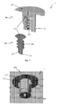
- Fig. 1 is a perspective view of a cross section of a valve for a ball.
- a valve 1 having a casing 100 and a core 200 can seen.
- Core 200 is at least partially arranged inside casing 100.
- Casing 100 comprises a cover area 112 and a recess 121.
- Cover area 112 preferably has a substantially larger diameter than the rest of casing 100 and thereby enables an extensive and therefore tight connection of casing 100 to a ball.
- cover area 112 may overlay a bladder of a ball so that the rest of casing 100 extends into the bladder through an opening in the bladder. This opening is covered by cover area 112 which provides an airtight seal.
- the ball casing 100 For inflating the ball casing 100 comprises a hole 111 which extends into the core 200.
- Core 200 has a thin pipe 211 in extension of hole 111, in order to enable insertion of the needle-like top of a pump for a ball into the interior of the ball.
- Thin pipe 211 is compressed by the elastic material of the core 211 so that no air can leak through thin pipe 211.
- casing 100 encloses core 200 so that there are no spaces between the core 200 and the casing 100 with the result that leakage of air along the contact surface of casing 100 and core 200 is not possible either.
- Recess 121 serves as a receptacle for windings of an electromagnetic coil (not illustrated in fig. 1 ) which can be used to inductively charge an energy storage (not illustrated in fig. 1 ) arranged inside the ball.
- an electronic device (not illustrated in fig. 1 ) which may comprise a pressure sensor, an acceleration sensor, a temperature sensor and further sensors and circuitry for measuring properties of the ball, its position and its motion.
- FIG. 2 shows further details of the valve of Fig. 1 .
- Fig. 2 shows valve 1, casing 100 with cover area 112 and recess 121, core 200, and hole 111.
- Casing 100 and core 200 are rotationally symmetric around axis 10.
- casing 100 and core 200 are not rotationally symmetric and may have, for example, an angular, in particular a rectangular shape.
- Outer end 110 of casing 100 is the end of casing 100 which is connected via cover area 112 with the bladder of a ball.
- Cover area 112 rests with its lower side (i.e., with the side directed to inner end 120 of casing 100) on the outside of the bladder to which it is connected, for example, by gluing or welding.
- inner end 120 of casing 100 is the end which extends into the ball.
- core 200 has an outer end 210 and an inner end 220.
- Recess 121 for receiving an electromagnetic coil is located at inner end 120 of casing 100.
- recess 121 is inclined with respect to axis 10 towards the outer end 110 of casing 100.
- recess 121 has a different inclination and / or a different shape; for example, recess 121 may run in parallel to axis 10, or it may be curved.
- An electromagnetic coil arranged in recess 121 can be used as a counter weight for balancing further electronic devices arranged inside a ball which will be explained in connection with fig. 9 below. Alternatively, a simple weight or other mass can be arranged in recess 121.
- Fig. 2 further shows an area 115 arranged between cover area 112 of casing 100 and outer boundary 213 of core 200.
- the height of area 115 has been chosen such that it is suitable to arrange indentations for receiving lighting means. This will be explained in more detail in connection with Fig. 4 below.
- Fig. 2 also shows further features of core 200, in particular a first sealing area 230 arranged between inner end 220 and outer end 210 of core 200.
- the first sealing area 230 comprises a plurality of concave sections 231 and convex sections 232, wherein the sections abut on each other. Alternatively, the sections can be separated by a straight section.
- Each convex section 232 engages a corresponding concave section 132 of a second sealing area 130 of casing 100
- each concave section 231 of core 200 engages a corresponding convex section 131 of casing 100.
- Casing 100 therefore encloses core 200 so that there are no spaces between core 200 and casing 100 and thereby enables a high leak tightness of valve 1.
- concave sections 231 and convex sections 232 of core 200 are arranged in an alternating sequence and abut on each other.
- the shape of the first sealing area 230 shown in Fig. 2 having three convex sections 232 with two concave sections 231 arranged between them. Therefore, the corresponding second sealing area 130 of casing 100 comprises three concave sections 132 and two convex sections 131.
- this sequence of convex and concave sections can be varied.
- a concave section maybe followed by another concave section. This holds correspondingly for convex sections.
- the first sealing area comprises only one concave and one convex section which abut on each other.
- the first sealing area comprises two convex sections and one concave section arranged between them.
- a sequence of concave and convex sections provides high leak tightness between core 200 and casing 100.
- the planes and edges of valves known from the prior art for example rectangular indentations or projections, lead to air leakage.
- One reason for this air leakage is that deformations of planes and edges may lead to displacements between the surfaces of the core and the casing. This may then create cavities through which air can escape (see summary of the invention). It is therefore particularly preferred if the first sealing area 230 of core 200 (thus also the second sealing area 130 of casing 100) is continuously curved so that this area has no edges or planes.
- Fig. 2 also shows that the shape of concave and convex sections 231, 232 is essentially semicircular. This shape leads to a maximum contact surface between the first sealing area 230 and the second sealing area 130 and to an optimum engagement of both sealing areas which improves the leak tightness.
- Fig. 2 also shows that inner end 220 of core 200 extends beyond casing 100 and terminates with a hemisphere 221.
- the shape of hemisphere 221 improves the leak tightness of the valve for the following reason:
- the thin pipe 211 (see Fig. 1 ) for inserting a pump into the inside of the ball has its exit point in the area of the hemisphere 221. Since the air pressure inside the ball evenly compresses hemisphere 221 from all sides and directions, tube 211 is also compressed which avoids air leakage through tube 211.
- a further advantage of a hemisphere is that it can be easily manufactured and does not require trimming.
- Fig. 2 further shows a third sealing area 240 arranged at outer end 210 of core 200 which has a convex section 241 and two concave sections 242.
- the third sealing area 240 comprises one ore more first edges 243.
- the third sealing area 240 has a larger diameter than the first sealing area 230.
- Third sealing area 240 therefore provides a firm positioning of core 200 inside casing 100 in case of forces acting along axis 10. This is, since the larger diameter and edges 243 prevent displacements along axis 10. Such forces arise, for example, during insertion and extraction of a ball pump. Arranging the third sealing area 240 at the outer end 210 of core 200 is therefore particularly advantageous since the ball pump exerts particularly large forces exactly at this point.
- Third sealing area 240 corresponds in turn to a fourth sealing area 140 of casing 100, as in the case of the first sealing area 230 and the second sealing area 130.
- the fourth sealing area 140 comprises in particular one or more second edges 143 which engage the corresponding first edges 243 of core 200.
- Fig. 3 is an exploded view of the cross section of Fig. 1 in which valve 1, casing 100 with cover area 112 and recess 121, core 200, hole 111, and thin pipe 211 can be recognized.
- Fig. 3 shows particularly well how cavity 101 of casing 100 corresponds to core 200 which provides a flush fit and therefore leak tightness between casing 100 and core 200. Since both, core 200 and casing 100, are made from elastic materials, valve 1 is leak tight also during deformations.
- Fig. 3 also illustrates how the strong curvature increases surface 201 of core 200 and thereby improves leak tightness of valve 1.
- the casing and the core are produced separately, and the core is subsequently pressed through an opening into the casing.
- this method has several disadvantages.
- the casing is stretched during insertion and may be damaged.
- the shape of the core has to be limited so that it can be introduced into the casing. The larger the diameter of the core, the more difficult is the insertion into the casing and the risk of damage. It is therefore desired to have a method of manufacture which does not require inserting core 200 into casing 100. This has the further advantage of eliminating a step of the manufacturing process.
- Such a method of manufacture of valve 1 which represents a further aspect of the present invention essentially comprises two steps.
- core 200 is produced from a first elastic material.
- the first elastic material comprises a rubber material.
- Core 200 is preferably formed by pressing or injection moulding.
- the first elastic material comprises TPU (Thermoplastic Polyurethane), in which case core 200 is produced by injection moulding.
- core 200 is made from other elastic materials and related production methods.
- casing 100 is injection-moulded around the core using a second material which is preferably transparent and which preferably comprises TPU.
- casing 100 is made from different elastic materials and the related production methods.
- core 200 is punctured with a needle to generate thin tube 211 as an extension of hole 111. The needle exits core 200 at the top of hemisphere 221.
- core 200 is arranged in a mould after its production, i.e. after the first step, and in the second step the casing is formed in the mould by injection moulding around core 200.
- the mould is a conventional mould as used for the manufacture of plastic parts. Use of a mould enables the application of advantageous shaping techniques of which injection moulding is particularly preferred. However, other techniques such as pressing or extruding are conceivable.
- the core is held in place by at least one needle.
- core 200 can be held in place in the mould by a fixture, in particular a needle, placed in hole 111.
- a ball valve 1 For the manufacture of a ball valve 1 is connected to the bladder of a ball.
- casing 100 is pushed through an opening into the bladder.
- the diameter of the opening is essentially equal to the diameter of the casing 100 at the inner end 120 (see Fig. 2 ).
- the bottom side of the cover area 112 is connected to the outside of the bladder, for example by gluing or welding.
- Fig. 4 is a perspective view of an embodiment of a valve for a ball which shows valve 1, casing 100 with cover area 112, and recess 121. In this view, only hemisphere 221 of core 200 is visible.
- Casing 100 can be manufactured, for example, from TPU or rubber material (such as vinyl).
- the bladder is preferably produced from the same material as casing 100.
- Use of a (transparent or translucent) material is preferred since it is cheaper than TPU.
- receptacles 116 for lighting means are arranged in area 115 below cover area 112 of casing 100.
- Receptacle 116 comprises an indentation 117 in casing 100 for receiving the lighting means and a bracing 118 of casing 100.
- casing 100 can be used as housing for the lighting means which emit their light to the outside through cover area 112 of a transparent casing 100. This saves separate housings for the lighting means.
- the light may escape either through projections arranged on casing 100 or through holes in casing 100 arranged above the lighting means and through further openings in the layers of the ball (carcass and outer layer) above the valve to the outside.
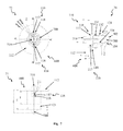
- FIG. 5 shows schematic representations of an embodiment of a valve for a ball.
- This figure shows a side view 51, a bottom view 52, a cross section 53 along the line A-A from bottom view 52, and a cross section 54 along the line B-B from bottom view 52.
- casing 100 with cover area 112 and recess 121 for receiving an electromagnetic coil as well as core 200 can be seen.
- Fig. 5 further shows in views 51, 52, and 54 receptacles 116 for lighting means, each with an indentation 117 and a bracing 118.
- preferably hemispherical projections 119 are arranged on cover area 112 of (transparent) casing 100.
- the projections 119 are arranged above indentations 117 for receiving the lighting means.
- Projections 119 emit the light of the lighting means broadly and therefore provide a good visibility of the lighting means. Small openings are provided in the layers of the ball (carcass and outer layer) above projections 119 to enable escape of the light.
- Projections 119 have a height which preferably corresponds to the thickness of the layers of the ball.
- Fig. 6 is a schematic representation of a preferred embodiment of a core for a valve of a ball. This figure shows a side view 61, a bottom view 62 and a cross-section 63 along the line B-B from the bottom view 62 of a core 200. Preferred dimensions of a core 200 can be directly read from the figure. For example, in the embodiment of Fig. 6 the curvature radii of concave sections 231 and convex sections 232 of core 200 each have a value of 0.75 mm.
- Fig. 7 is a schematic representation of a further embodiment of a valve for a ball. This figure shows a side view 71, a bottom view 72, and a cross-section 74 along the line B-B from bottom view 72. Again, casing 600 with cover area 112 and recess 121 for an electromagnetic coil as well as core 700 can be recognized.
- contour 702 of core 700 does not correspond to the (inner) contour, comprising concave 132 and convex 131 sections, of casing 600, in contrast to the previously described embodiments. Rather, contour 702 of core 700 is only slightly curved and comprises essentially only one concave section 731 and two adjacent convex sections. By contrast, the contour of casing 600 is curved more noticeable and comprises several concave sections 132 and convex sections 131, preferably four concave sections 132 and three convex sections 131, which can be recognized in the views 73 and 74.
- Core 700 and casing 600 are separately manufactured, and core 700 is subsequently inserted into casing 600. Since core 700 is made from an elastic material (for example rubber) and since casing 600 is made from an elastic material (for example TPU), core 700 adjusts its form to casing 600. Before inserting core 700 into casing 600, the contours of core 700 and casing 600 are different. When core 700 is inserted, its contour adjusts to the contour of casing 600. Fig. 7 shows casing 600 and the inserted core 700, wherein core 700 still has its original contour which is not yet adjusted to the contour of casing 600.
- core 700 is made from an elastic material (for example rubber) and since casing 600 is made from an elastic material (for example TPU)
- core 700 adjusts its form to casing 600. Before inserting core 700 into casing 600, the contours of core 700 and casing 600 are different. When core 700 is inserted, its contour adjusts to the contour of casing 600.
- Fig. 7 shows casing 600 and the inserted core 700, wherein core 700 still has
- the contour of casing 600 comprising concave 132 and convex 131 sections, is not flush with contour 702 of core 700. Nevertheless, also in this embodiment the valve is leak tight since in particular the convex sections 131 of casing 600 exert a high pressure on contour 702 of core 700 so that leak tightness is secured.
- Views 71, 72 and 74 of fig. 7 further show receptacles 116 for lighting means, wherein each receptacle 116 has an indentation 117 and a bracing 118.
- a projection 719 is arranged in the centre of cover area 112 of (transparent) casing 100, in contrast to the projections 119 in Fig. 5 .
- projection 719 has a cylindrical shape. Projection 719 collects the light from the lighting means which are arranged in indentations 117 below projection 719 and emits the collected light broadly. This provides a good visibility of the lighting means.
- Fig. 8 is a schematic representation of a further embodiment of a valve for a ball with a casing 800 and a core 700.
- contour 802 of casing 800 corresponds to contour 702 of core 700, so that both contours are flush and provide high leak tightness.
- Contour 702 of core 700 is only slightly curved, similar to Fig. 7 , and comprises a first sealing area 730 with a concave section 731 and two convex sections 732.
- contour 802 of casing 800 is only slightly curved and comprises a second sealing area 830 corresponding in shape to the first sealing area 730. The flush fit of the contours and their slight curvature simplifies insertion of core 700 into casing 800 and reduces the risk of damage.
- Core 700 and casing 800 can separately manufactured, wherein core 700 is inserted into casing 800 after manufacture.
- casing 800 can be injection-moulded around core 700.
- a further aspect of the present invention relates to a ball which comprises a valve 1 as described above.
- a ball further comprises an electronic device and an energy storage.
- the energy storage can be inductively charged by an electromagnetic coil which is formed by windings in recess 121 of casing 100. This avoids the need for a further component, i.e. an electromagnetic coil, inside the ball.
- States of the electronic device can be displayed by lighting means which are arranged in one or more receptacles 116 of casing 100. For example, a red lighting means can display a too low and / or a too high pressure of the ball, and a green lighting means can display an adequate pressure inside the ball. Alternatively, a single lighting means may be used.
- One or more lighting means may display the charging state of the energy storage (for example, a battery or a capacitor).
- the electronic device may comprise a pressure sensor, an acceleration sensor, a temperature sensor and further sensors and circuitry for measuring properties of the ball, its position and its motion.
- Fig. 9 shows an alternative embodiment of a valve and an electromagnetic coil.
- a bladder 10 of a ball having a valve 1 and an electromagnetic coil 901 can be seen.
- Electromagnetic coil 901 is arranged on the bladder 10 and surrounds valve 1 in a circular arrangement.
- electromagnetic coil 901 is arranged at other positions on the bladder 10, wherein the distance to an electric magnetic field of a charging station is relevant. The closer electromagnetic coil 901 is located to the electromagnetic field of a charging station, the faster an energy storage connected to electromagnetic coil 901 can be charged, and the less energy is needed.
- Arranging the electromagnetic coil 901 on the bladder 10, wherein the electromagnetic coil 901 is arranged in a circular arrangement around valve 1, results in a particularly short distance to the electromagnetic field of a charging station and thereby enables fast charging.
- Fig. 9 further shows that electromagnetic coil 901 is connected by connection wires 902 to valve 1.
- electromagnetic coil 901 is arranged in a tunnel of bladder 10.
- electromagnetic coil 901 is attached to bladder 10 by other fixing means, for example gluing or welding.
- Fig. 10 shows an embodiment of a charging station 910 for a ball 900 having an energy storage.
- ball 900 is placed in charging station 910 for charging the energy storage.
- valve 1 (not visible) of ball 900 is brought into the proximity of a charging coil (not illustrated) of charging station 910. Therefore, charging station 910 is designed so that the ball can be easily rotated.
- Charging station 910 can be equipped with a display which signals when the coil inside the ball is sufficiently close to the charging coil of charging station 910 and when charging is finished.
- Fig. 11 shows a further embodiment of a charging station for a ball having an energy storage.
- the illustrated charging station 910 comprises a recess 911 for a ball.
- charging station 910 comprises a display 914 in a controller 913, for example a microcontroller, which is removed from charging station 910 in the representation of Fig. 11 .
- controller 913 is arranged inside charging station 910.
- Display 914 can be arranged, for example, at the surface of charging station 910.
- Display 914 indicates whether a ball is in an adequate position in the charging station 910 for charging an energy storage inside the ball.
- charging station 910 comprises a second electromagnetic coil 912 which can be arranged, for example, at the bottom of recess 911. In further embodiments, the second electromagnetic coil 912 can be arranged at other positions of charging station 910.
- Controller 913 of charging station 910 measures the signal which changes according to the different orientations of the ball inside charging station 910 with respect to the second electromagnetic coil 912. Controller 913 recognizes when the electromagnetic coil inside the ball is in an adequate position for charging.
- An adequate position for charging is displayed by display 914.
- display 914 In further embodiments, several displays are used, also with different colors. The brightness of the display can be used to indicate the distance of the electromagnetic coil inside the ball to an adequate position for charging.
- Arranging one or more electronic devices and energy storages inside a ball requires balancing the ball, in order to avoid a negative impact on a smooth motion of the ball.
- the valve is used as a mounting for an electromagnetic coil since this avoids a further component inside the ball. This also saves weight.
- the valve and the electromagnetic coil itself can be used as a counterweight for an energy storage and an electronic device. It is even possible to use the valve and the electromagnetic coil as a variable counter weight for balancing by varying the shape of recess 121 (see Fig. 1 to 5 , 7 ), material, wire thickness, number of windings and other parameters of the electromagnetic coil.
Landscapes
- Engineering & Computer Science (AREA)
- Health & Medical Sciences (AREA)
- General Health & Medical Sciences (AREA)
- Physical Education & Sports Medicine (AREA)
- General Engineering & Computer Science (AREA)
- Mechanical Engineering (AREA)
- Life Sciences & Earth Sciences (AREA)
- Biophysics (AREA)
- Manufacturing & Machinery (AREA)
- Check Valves (AREA)
- Taps Or Cocks (AREA)
- Valve Housings (AREA)
- Indication Of The Valve Opening Or Closing Status (AREA)
Applications Claiming Priority (1)
| Application Number | Priority Date | Filing Date | Title |
|---|---|---|---|
| DE102008058821.0A DE102008058821B4 (de) | 2008-11-25 | 2008-11-25 | Ballventil und Verfahren zur Herstellung eines Ballventils |
Publications (3)
| Publication Number | Publication Date |
|---|---|
| EP2189266A2 true EP2189266A2 (fr) | 2010-05-26 |
| EP2189266A3 EP2189266A3 (fr) | 2010-07-28 |
| EP2189266B1 EP2189266B1 (fr) | 2016-03-23 |
Family
ID=41786092
Family Applications (1)
| Application Number | Title | Priority Date | Filing Date |
|---|---|---|---|
| EP09174335.1A Not-in-force EP2189266B1 (fr) | 2008-11-25 | 2009-10-28 | Soupape pour ballon et son procédé de fabrication |
Country Status (5)
| Country | Link |
|---|---|
| US (2) | US8292764B2 (fr) |
| EP (1) | EP2189266B1 (fr) |
| JP (2) | JP2010155071A (fr) |
| CN (1) | CN101732833A (fr) |
| DE (1) | DE102008058821B4 (fr) |
Cited By (4)
| Publication number | Priority date | Publication date | Assignee | Title |
|---|---|---|---|---|
| CN102359629A (zh) * | 2011-09-16 | 2012-02-22 | 宁波市鄞州金钢汽配厂 | 气门嘴芯制造方法 |
| DE102018205119A1 (de) | 2018-04-05 | 2019-10-10 | Adidas Ag | Ventileinheit für ein Ventil eines aufblasbaren Körpers |
| CN110772764A (zh) * | 2019-12-03 | 2020-02-11 | 北京联合东星贸易有限公司 | 应用于球体的气咀以及球体 |
| CN111565865A (zh) * | 2018-01-04 | 2020-08-21 | 纬湃技术有限公司 | 用于制造电磁阀装置的方法及电磁阀装置 |
Families Citing this family (14)
| Publication number | Priority date | Publication date | Assignee | Title |
|---|---|---|---|---|
| DE102008058821B4 (de) * | 2008-11-25 | 2016-01-21 | Adidas International Marketing B.V. | Ballventil und Verfahren zur Herstellung eines Ballventils |
| US20120244969A1 (en) | 2011-03-25 | 2012-09-27 | May Patents Ltd. | System and Method for a Motion Sensing Device |
| US8771115B2 (en) | 2011-05-04 | 2014-07-08 | Nike, Inc. | Sport ball with an inflation-retention bladder |
| US8672784B2 (en) | 2011-05-04 | 2014-03-18 | Nike, Inc. | Sport ball with an inflation-retention bladder |
| MX356995B (es) * | 2012-06-18 | 2018-06-22 | Basf Se | Válvula para una sección del tubo flexible inflable. |
| AU2013289839B2 (en) * | 2012-07-09 | 2015-10-29 | Catapult Sports Ltd | Tracking balls in sports |
| EP2741080A1 (fr) * | 2012-12-05 | 2014-06-11 | CTC Analytics AG | Dispositif et procédé destinés à injecter un liquide dans un appareil d'analyse |
| DE212014000054U1 (de) | 2013-02-22 | 2015-12-10 | Nsi International, Inc. | Ventilanordnung für aufblasbare Blase |
| US10465809B2 (en) * | 2013-02-22 | 2019-11-05 | Nsi International, Inc. | Valve assembly for expandable bladder and method of manufacturing the same |
| US10799769B2 (en) | 2015-03-19 | 2020-10-13 | Gigglicious, LLC | Two layer recreational air-tight object having a patterned illuminated surface |
| US10384626B2 (en) * | 2016-08-09 | 2019-08-20 | Ford Global Technologies, Llc | Vehicle power plug converter |
| USD826990S1 (en) * | 2016-11-09 | 2018-08-28 | Nsi International, Inc. | Valve |
| GB2591216B (en) * | 2019-10-25 | 2022-08-31 | Sportable Tech Ltd | Apparatus for an inflatable sports ball |
| US12285655B2 (en) * | 2024-10-14 | 2025-04-29 | Shenzhen Jiaxin Technology Co., Ltd. | Luminous ball |
Citations (4)
| Publication number | Priority date | Publication date | Assignee | Title |
|---|---|---|---|---|
| US1782198A (en) | 1930-01-25 | 1930-11-18 | James R Denkert | Inflatable playing ball and bladder therefor |
| US2295804A (en) | 1940-11-12 | 1942-09-15 | C B Webb Company | Valve for inflatable articles |
| DE3221749A1 (de) | 1982-06-09 | 1983-12-15 | Franz 4280 Borken Abbing | Ballventilabdichtung |
| US4568081A (en) | 1983-04-13 | 1986-02-04 | Wilson Sporting Goods Company | Inflation needle lubricating plug insert-type valve assembly |
Family Cites Families (46)
| Publication number | Priority date | Publication date | Assignee | Title |
|---|---|---|---|---|
| US1518901A (en) * | 1923-01-23 | 1924-12-09 | Charles F Collins | Valve plug for inflated bodies |
| US1867443A (en) * | 1930-02-24 | 1932-07-12 | Dieterle Frank | Casing and bladder connecter for footballs, basketballs, and the like |
| US1981720A (en) * | 1931-05-14 | 1934-11-20 | Seamless Rubber Company Inc | Valve for football bladders and the like |
| US1927725A (en) * | 1932-02-16 | 1933-09-19 | Kearsley Mitchell J | Valve for pneumatic devices |
| US2080894A (en) * | 1936-11-04 | 1937-05-18 | Levinson David | Inflatable ball |
| US2183900A (en) * | 1938-01-10 | 1939-12-19 | William J Voit | Inflation valve |
| US2387455A (en) * | 1945-07-16 | 1945-10-23 | Sun Rubber Co | Inflating valve for hollow articles |
| US2600862A (en) * | 1947-06-11 | 1952-06-17 | Sun Rubber Co | Inflation valve |
| US2710622A (en) * | 1951-04-26 | 1955-06-14 | Barr Rubber Products Company | One piece fluid valve |
| US3204959A (en) * | 1961-03-16 | 1965-09-07 | Mettoy Co Ltd | Hollow inflatable article |
| US3220729A (en) * | 1962-08-15 | 1965-11-30 | Nat Latex Prod Co | Tetherball or like inflatable article |
| AU1364066A (en) * | 1966-11-08 | 1966-05-09 | Schack Rubber Mills Limited | Improvements in valves for inflatable articles |
| NL7005909A (fr) | 1969-05-02 | 1970-11-04 | ||
| US3905387A (en) * | 1974-10-03 | 1975-09-16 | Munro M Grant | Needle type inflation valve |
| US4320776A (en) * | 1979-12-20 | 1982-03-23 | Yang Wen H | Construction of the ball bladder orifice |
| US4577865A (en) * | 1983-06-16 | 1986-03-25 | Molten Corporation | Athletic ball |
| JP2544929Y2 (ja) * | 1991-02-04 | 1997-08-20 | 株式会社モルテン | 運動用ボール |
| US5358001A (en) * | 1994-03-07 | 1994-10-25 | Smith Eldon F | Air valve for use in an inflatable bladder |
| DE19506502C2 (de) | 1995-02-24 | 1998-03-19 | Uhlsport Gmbh | Druckmeßeinrichtung für Bälle, insbesondere Fußbälle |
| GB9513843D0 (en) | 1995-07-07 | 1995-09-06 | James Gilbert Rugby Footballs | Rugby ball |
| US5735776A (en) * | 1995-07-31 | 1998-04-07 | Swezey; Robert L. | Isometric exercise ball |
| GB9700260D0 (en) | 1997-01-08 | 1997-02-26 | James Gilbert Rugby Footballs | Weighted rugby ball valve |
| US5856619A (en) * | 1997-05-13 | 1999-01-05 | Wang; Kuo-Tsai | Tire pressure indicator |
| US5755634A (en) * | 1997-05-19 | 1998-05-26 | Huang; Tien-Tsai | Inflatable ball with a digital pressure display |
| DE19800796A1 (de) * | 1998-01-13 | 1999-07-15 | Saga Sports Pvt Ltd | Blasenventil für einen ausblasbaren Ball |
| US5915407A (en) * | 1998-06-16 | 1999-06-29 | The National Latex Products Company | Ball with inflation valve sleeve for rapid deflation |
| TW389314U (en) * | 1999-03-12 | 2000-05-01 | Chen Min Fang | Equipment for measuring tire pressure |
| US20030224885A1 (en) * | 2002-06-04 | 2003-12-04 | Leal Jose E. | Illuminated ball |
| IT1331953B1 (it) * | 2002-09-17 | 2006-01-30 | Serena Capriotti | Camera d'aria con sensori elettronici all'interno che rilevano il passaggio del pallone sulla linea di porta anche se coperto da giocatori |
| WO2004083697A1 (fr) * | 2003-03-17 | 2004-09-30 | Global Valve Technology Pty Ltd | Valve pour ballon de sport |
| DE10338620B4 (de) | 2003-08-22 | 2007-11-22 | Cairos Technologies Ag | Ballsensor |
| DE10361826A1 (de) | 2003-12-30 | 2005-07-28 | Johannes Katz | Sportball, insbesondere Fussball |
| US20050288134A1 (en) * | 2004-06-25 | 2005-12-29 | Smith David K | Sensiball |
| DE102004045176B4 (de) * | 2004-09-17 | 2011-07-21 | Adidas International Marketing B.V. | Blase |
| US7175553B2 (en) * | 2005-01-13 | 2007-02-13 | Russell Corporation | Sport ball with self-contained inflation mechanism and pressure indicator |
| DE102005036355A1 (de) * | 2005-07-29 | 2007-02-01 | Cairos Technologies Ag | Verfahren zur Erfassung der Kraft- und Bewegungsverhältnisse an einem Spielgerät |
| US20070281811A1 (en) * | 2006-06-02 | 2007-12-06 | Chi-Hsien Wang | Ball with lighting device |
| DE102007013025A1 (de) * | 2007-01-02 | 2008-07-10 | Cairos Technologies Ag | Konzept zur Erfassung eines Innendrucks eines kompressiblen Gegenstandes |
| US20080274844A1 (en) * | 2007-05-03 | 2008-11-06 | Emd3 | False activation reducing centrifugal activation system |
| US8360904B2 (en) * | 2007-08-17 | 2013-01-29 | Adidas International Marketing Bv | Sports electronic training system with sport ball, and applications thereof |
| DE102008058943B3 (de) * | 2008-11-25 | 2010-05-12 | Adidas International Marketing B.V. | Blase für einen Ball |
| DE102008058821B4 (de) * | 2008-11-25 | 2016-01-21 | Adidas International Marketing B.V. | Ballventil und Verfahren zur Herstellung eines Ballventils |
| US8172722B2 (en) * | 2008-12-05 | 2012-05-08 | Nike, Inc. | Athletic performance monitoring systems and methods in a team sports environment |
| TWM369161U (en) * | 2009-03-05 | 2009-11-21 | yong-jie Huang | Radiation golf in wireless charging with sound and light control |
| US8870690B2 (en) * | 2009-11-19 | 2014-10-28 | Wilson Sporting Goods Co. | American-style football including electronics |
| US20120244969A1 (en) * | 2011-03-25 | 2012-09-27 | May Patents Ltd. | System and Method for a Motion Sensing Device |
-
2008
- 2008-11-25 DE DE102008058821.0A patent/DE102008058821B4/de not_active Expired - Fee Related
-
2009
- 2009-10-28 EP EP09174335.1A patent/EP2189266B1/fr not_active Not-in-force
- 2009-11-18 US US12/621,148 patent/US8292764B2/en active Active
- 2009-11-25 JP JP2009267310A patent/JP2010155071A/ja active Pending
- 2009-11-25 CN CN200910224202A patent/CN101732833A/zh active Pending
-
2012
- 2012-09-14 US US13/617,712 patent/US8771110B2/en active Active
-
2013
- 2013-05-20 JP JP2013105948A patent/JP5886239B2/ja active Active
Patent Citations (4)
| Publication number | Priority date | Publication date | Assignee | Title |
|---|---|---|---|---|
| US1782198A (en) | 1930-01-25 | 1930-11-18 | James R Denkert | Inflatable playing ball and bladder therefor |
| US2295804A (en) | 1940-11-12 | 1942-09-15 | C B Webb Company | Valve for inflatable articles |
| DE3221749A1 (de) | 1982-06-09 | 1983-12-15 | Franz 4280 Borken Abbing | Ballventilabdichtung |
| US4568081A (en) | 1983-04-13 | 1986-02-04 | Wilson Sporting Goods Company | Inflation needle lubricating plug insert-type valve assembly |
Cited By (5)
| Publication number | Priority date | Publication date | Assignee | Title |
|---|---|---|---|---|
| CN102359629A (zh) * | 2011-09-16 | 2012-02-22 | 宁波市鄞州金钢汽配厂 | 气门嘴芯制造方法 |
| CN111565865A (zh) * | 2018-01-04 | 2020-08-21 | 纬湃技术有限公司 | 用于制造电磁阀装置的方法及电磁阀装置 |
| DE102018205119A1 (de) | 2018-04-05 | 2019-10-10 | Adidas Ag | Ventileinheit für ein Ventil eines aufblasbaren Körpers |
| CN110772764A (zh) * | 2019-12-03 | 2020-02-11 | 北京联合东星贸易有限公司 | 应用于球体的气咀以及球体 |
| CN110772764B (zh) * | 2019-12-03 | 2024-01-02 | 北京联合东星贸易有限公司 | 应用于球体的气咀以及球体 |
Also Published As
| Publication number | Publication date |
|---|---|
| US8771110B2 (en) | 2014-07-08 |
| US20130012345A1 (en) | 2013-01-10 |
| EP2189266A3 (fr) | 2010-07-28 |
| US8292764B2 (en) | 2012-10-23 |
| JP5886239B2 (ja) | 2016-03-16 |
| DE102008058821A1 (de) | 2010-05-27 |
| CN101732833A (zh) | 2010-06-16 |
| US20100130316A1 (en) | 2010-05-27 |
| JP2010155071A (ja) | 2010-07-15 |
| DE102008058821B4 (de) | 2016-01-21 |
| EP2189266B1 (fr) | 2016-03-23 |
| JP2013176617A (ja) | 2013-09-09 |
Similar Documents
| Publication | Publication Date | Title |
|---|---|---|
| EP2189266B1 (fr) | Soupape pour ballon et son procédé de fabrication | |
| US8517869B2 (en) | Bladder for a ball | |
| US20100130314A1 (en) | Oval ball, especially rugby ball or football | |
| CN105944339A (zh) | 一种球、尤其是英式足球及制球方法 | |
| JP6859112B2 (ja) | 柔軟な器具用グリップ | |
| WO2008140508A1 (fr) | Fixation de dispositif de surveillance à des tiges de valve en caoutchouc | |
| US7175553B2 (en) | Sport ball with self-contained inflation mechanism and pressure indicator | |
| EP4363071A1 (fr) | Sabre gonflable extensible | |
| US7278937B2 (en) | Sport ball with self-contained inflation mechanism having pressure relief and indication capability | |
| CN1674962A (zh) | 带有指示压力的自备充气机构的运动球 | |
| CN1691972A (zh) | 具有能够卸压的自备充气机构的运动球 | |
| WO2004085006A1 (fr) | Balle de golf | |
| JP2006511319A (ja) | 内蔵式複式膨張機構を備えるスポーツ・ボール | |
| US20030181272A1 (en) | Inflatable game ball and method for manufacturing the same | |
| CN208877846U (zh) | 一种发光空心球 | |
| US20040048705A1 (en) | Sport ball with pump having pressure relief and/or pressure indication capability | |
| US20040198147A1 (en) | Sport ball with self-contained dual action inflation mechanism | |
| CN207691470U (zh) | 智能球的充电结构 | |
| CN108185574B (zh) | 一种具有足底压力预警功能的鞋底 | |
| KR20200133226A (ko) | 펌핑 기구 인서트 | |
| US20250135298A1 (en) | Hollow ball structure based on supercritical process | |
| CN207708446U (zh) | 一种与球胆为一体的篮球结构 | |
| US20160263954A1 (en) | Valve stem core module | |
| US9855468B1 (en) | Elastic spheroid structure |
Legal Events
| Date | Code | Title | Description |
|---|---|---|---|
| PUAI | Public reference made under article 153(3) epc to a published international application that has entered the european phase |
Free format text: ORIGINAL CODE: 0009012 |
|
| AK | Designated contracting states |
Kind code of ref document: A2 Designated state(s): AT BE BG CH CY CZ DE DK EE ES FI FR GB GR HR HU IE IS IT LI LT LU LV MC MK MT NL NO PL PT RO SE SI SK SM TR |
|
| AX | Request for extension of the european patent |
Extension state: AL BA RS |
|
| PUAL | Search report despatched |
Free format text: ORIGINAL CODE: 0009013 |
|
| AK | Designated contracting states |
Kind code of ref document: A3 Designated state(s): AT BE BG CH CY CZ DE DK EE ES FI FR GB GR HR HU IE IS IT LI LT LU LV MC MK MT NL NO PL PT RO SE SI SK SM TR |
|
| AX | Request for extension of the european patent |
Extension state: AL BA RS |
|
| RIC1 | Information provided on ipc code assigned before grant |
Ipc: B29C 45/16 20060101AFI20100312BHEP Ipc: A63B 43/06 20060101ALI20100623BHEP Ipc: A63B 41/08 20060101ALI20100623BHEP Ipc: F16K 15/20 20060101ALI20100623BHEP Ipc: A63B 47/00 20060101ALI20100623BHEP |
|
| 17P | Request for examination filed |
Effective date: 20110128 |
|
| 17Q | First examination report despatched |
Effective date: 20120412 |
|
| GRAP | Despatch of communication of intention to grant a patent |
Free format text: ORIGINAL CODE: EPIDOSNIGR1 |
|
| INTG | Intention to grant announced |
Effective date: 20150408 |
|
| GRAP | Despatch of communication of intention to grant a patent |
Free format text: ORIGINAL CODE: EPIDOSNIGR1 |
|
| INTG | Intention to grant announced |
Effective date: 20150916 |
|
| GRAS | Grant fee paid |
Free format text: ORIGINAL CODE: EPIDOSNIGR3 |
|
| GRAA | (expected) grant |
Free format text: ORIGINAL CODE: 0009210 |
|
| AK | Designated contracting states |
Kind code of ref document: B1 Designated state(s): AT BE BG CH CY CZ DE DK EE ES FI FR GB GR HR HU IE IS IT LI LT LU LV MC MK MT NL NO PL PT RO SE SI SK SM TR |
|
| REG | Reference to a national code |
Ref country code: GB Ref legal event code: FG4D |
|
| REG | Reference to a national code |
Ref country code: CH Ref legal event code: EP |
|
| REG | Reference to a national code |
Ref country code: AT Ref legal event code: REF Ref document number: 782681 Country of ref document: AT Kind code of ref document: T Effective date: 20160415 |
|
| REG | Reference to a national code |
Ref country code: IE Ref legal event code: FG4D |
|
| REG | Reference to a national code |
Ref country code: DE Ref legal event code: R096 Ref document number: 602009036969 Country of ref document: DE |
|
| REG | Reference to a national code |
Ref country code: LT Ref legal event code: MG4D |
|
| REG | Reference to a national code |
Ref country code: NL Ref legal event code: MP Effective date: 20160323 |
|
| PG25 | Lapsed in a contracting state [announced via postgrant information from national office to epo] |
Ref country code: GR Free format text: LAPSE BECAUSE OF FAILURE TO SUBMIT A TRANSLATION OF THE DESCRIPTION OR TO PAY THE FEE WITHIN THE PRESCRIBED TIME-LIMIT Effective date: 20160624 Ref country code: FI Free format text: LAPSE BECAUSE OF FAILURE TO SUBMIT A TRANSLATION OF THE DESCRIPTION OR TO PAY THE FEE WITHIN THE PRESCRIBED TIME-LIMIT Effective date: 20160323 Ref country code: NO Free format text: LAPSE BECAUSE OF FAILURE TO SUBMIT A TRANSLATION OF THE DESCRIPTION OR TO PAY THE FEE WITHIN THE PRESCRIBED TIME-LIMIT Effective date: 20160623 |
|
| REG | Reference to a national code |
Ref country code: AT Ref legal event code: MK05 Ref document number: 782681 Country of ref document: AT Kind code of ref document: T Effective date: 20160323 |
|
| PG25 | Lapsed in a contracting state [announced via postgrant information from national office to epo] |
Ref country code: SE Free format text: LAPSE BECAUSE OF FAILURE TO SUBMIT A TRANSLATION OF THE DESCRIPTION OR TO PAY THE FEE WITHIN THE PRESCRIBED TIME-LIMIT Effective date: 20160323 Ref country code: LT Free format text: LAPSE BECAUSE OF FAILURE TO SUBMIT A TRANSLATION OF THE DESCRIPTION OR TO PAY THE FEE WITHIN THE PRESCRIBED TIME-LIMIT Effective date: 20160323 Ref country code: LV Free format text: LAPSE BECAUSE OF FAILURE TO SUBMIT A TRANSLATION OF THE DESCRIPTION OR TO PAY THE FEE WITHIN THE PRESCRIBED TIME-LIMIT Effective date: 20160323 Ref country code: NL Free format text: LAPSE BECAUSE OF FAILURE TO SUBMIT A TRANSLATION OF THE DESCRIPTION OR TO PAY THE FEE WITHIN THE PRESCRIBED TIME-LIMIT Effective date: 20160323 |
|
| REG | Reference to a national code |
Ref country code: FR Ref legal event code: PLFP Year of fee payment: 8 |
|
| PG25 | Lapsed in a contracting state [announced via postgrant information from national office to epo] |
Ref country code: IS Free format text: LAPSE BECAUSE OF FAILURE TO SUBMIT A TRANSLATION OF THE DESCRIPTION OR TO PAY THE FEE WITHIN THE PRESCRIBED TIME-LIMIT Effective date: 20160723 Ref country code: EE Free format text: LAPSE BECAUSE OF FAILURE TO SUBMIT A TRANSLATION OF THE DESCRIPTION OR TO PAY THE FEE WITHIN THE PRESCRIBED TIME-LIMIT Effective date: 20160323 Ref country code: PL Free format text: LAPSE BECAUSE OF FAILURE TO SUBMIT A TRANSLATION OF THE DESCRIPTION OR TO PAY THE FEE WITHIN THE PRESCRIBED TIME-LIMIT Effective date: 20160323 |
|
| PG25 | Lapsed in a contracting state [announced via postgrant information from national office to epo] |
Ref country code: SK Free format text: LAPSE BECAUSE OF FAILURE TO SUBMIT A TRANSLATION OF THE DESCRIPTION OR TO PAY THE FEE WITHIN THE PRESCRIBED TIME-LIMIT Effective date: 20160323 Ref country code: AT Free format text: LAPSE BECAUSE OF FAILURE TO SUBMIT A TRANSLATION OF THE DESCRIPTION OR TO PAY THE FEE WITHIN THE PRESCRIBED TIME-LIMIT Effective date: 20160323 Ref country code: CZ Free format text: LAPSE BECAUSE OF FAILURE TO SUBMIT A TRANSLATION OF THE DESCRIPTION OR TO PAY THE FEE WITHIN THE PRESCRIBED TIME-LIMIT Effective date: 20160323 Ref country code: RO Free format text: LAPSE BECAUSE OF FAILURE TO SUBMIT A TRANSLATION OF THE DESCRIPTION OR TO PAY THE FEE WITHIN THE PRESCRIBED TIME-LIMIT Effective date: 20160323 Ref country code: SM Free format text: LAPSE BECAUSE OF FAILURE TO SUBMIT A TRANSLATION OF THE DESCRIPTION OR TO PAY THE FEE WITHIN THE PRESCRIBED TIME-LIMIT Effective date: 20160323 Ref country code: PT Free format text: LAPSE BECAUSE OF FAILURE TO SUBMIT A TRANSLATION OF THE DESCRIPTION OR TO PAY THE FEE WITHIN THE PRESCRIBED TIME-LIMIT Effective date: 20160725 Ref country code: ES Free format text: LAPSE BECAUSE OF FAILURE TO SUBMIT A TRANSLATION OF THE DESCRIPTION OR TO PAY THE FEE WITHIN THE PRESCRIBED TIME-LIMIT Effective date: 20160323 |
|
| PG25 | Lapsed in a contracting state [announced via postgrant information from national office to epo] |
Ref country code: BE Free format text: LAPSE BECAUSE OF FAILURE TO SUBMIT A TRANSLATION OF THE DESCRIPTION OR TO PAY THE FEE WITHIN THE PRESCRIBED TIME-LIMIT Effective date: 20160323 Ref country code: IT Free format text: LAPSE BECAUSE OF FAILURE TO SUBMIT A TRANSLATION OF THE DESCRIPTION OR TO PAY THE FEE WITHIN THE PRESCRIBED TIME-LIMIT Effective date: 20160323 |
|
| REG | Reference to a national code |
Ref country code: DE Ref legal event code: R097 Ref document number: 602009036969 Country of ref document: DE |
|
| PLBE | No opposition filed within time limit |
Free format text: ORIGINAL CODE: 0009261 |
|
| STAA | Information on the status of an ep patent application or granted ep patent |
Free format text: STATUS: NO OPPOSITION FILED WITHIN TIME LIMIT |
|
| PG25 | Lapsed in a contracting state [announced via postgrant information from national office to epo] |
Ref country code: DK Free format text: LAPSE BECAUSE OF FAILURE TO SUBMIT A TRANSLATION OF THE DESCRIPTION OR TO PAY THE FEE WITHIN THE PRESCRIBED TIME-LIMIT Effective date: 20160323 |
|
| PG25 | Lapsed in a contracting state [announced via postgrant information from national office to epo] |
Ref country code: BG Free format text: LAPSE BECAUSE OF FAILURE TO SUBMIT A TRANSLATION OF THE DESCRIPTION OR TO PAY THE FEE WITHIN THE PRESCRIBED TIME-LIMIT Effective date: 20160623 |
|
| 26N | No opposition filed |
Effective date: 20170102 |
|
| PG25 | Lapsed in a contracting state [announced via postgrant information from national office to epo] |
Ref country code: SI Free format text: LAPSE BECAUSE OF FAILURE TO SUBMIT A TRANSLATION OF THE DESCRIPTION OR TO PAY THE FEE WITHIN THE PRESCRIBED TIME-LIMIT Effective date: 20160323 |
|
| REG | Reference to a national code |
Ref country code: CH Ref legal event code: PL |
|
| REG | Reference to a national code |
Ref country code: IE Ref legal event code: MM4A |
|
| PG25 | Lapsed in a contracting state [announced via postgrant information from national office to epo] |
Ref country code: CH Free format text: LAPSE BECAUSE OF NON-PAYMENT OF DUE FEES Effective date: 20161031 Ref country code: LI Free format text: LAPSE BECAUSE OF NON-PAYMENT OF DUE FEES Effective date: 20161031 |
|
| PG25 | Lapsed in a contracting state [announced via postgrant information from national office to epo] |
Ref country code: LU Free format text: LAPSE BECAUSE OF NON-PAYMENT OF DUE FEES Effective date: 20161028 |
|
| REG | Reference to a national code |
Ref country code: FR Ref legal event code: PLFP Year of fee payment: 9 |
|
| PG25 | Lapsed in a contracting state [announced via postgrant information from national office to epo] |
Ref country code: IE Free format text: LAPSE BECAUSE OF NON-PAYMENT OF DUE FEES Effective date: 20161028 |
|
| PG25 | Lapsed in a contracting state [announced via postgrant information from national office to epo] |
Ref country code: HU Free format text: LAPSE BECAUSE OF FAILURE TO SUBMIT A TRANSLATION OF THE DESCRIPTION OR TO PAY THE FEE WITHIN THE PRESCRIBED TIME-LIMIT; INVALID AB INITIO Effective date: 20091028 Ref country code: CY Free format text: LAPSE BECAUSE OF FAILURE TO SUBMIT A TRANSLATION OF THE DESCRIPTION OR TO PAY THE FEE WITHIN THE PRESCRIBED TIME-LIMIT Effective date: 20160323 |
|
| PG25 | Lapsed in a contracting state [announced via postgrant information from national office to epo] |
Ref country code: MK Free format text: LAPSE BECAUSE OF FAILURE TO SUBMIT A TRANSLATION OF THE DESCRIPTION OR TO PAY THE FEE WITHIN THE PRESCRIBED TIME-LIMIT Effective date: 20160323 Ref country code: MT Free format text: LAPSE BECAUSE OF NON-PAYMENT OF DUE FEES Effective date: 20161031 Ref country code: TR Free format text: LAPSE BECAUSE OF FAILURE TO SUBMIT A TRANSLATION OF THE DESCRIPTION OR TO PAY THE FEE WITHIN THE PRESCRIBED TIME-LIMIT Effective date: 20160323 Ref country code: MC Free format text: LAPSE BECAUSE OF FAILURE TO SUBMIT A TRANSLATION OF THE DESCRIPTION OR TO PAY THE FEE WITHIN THE PRESCRIBED TIME-LIMIT Effective date: 20160323 Ref country code: HR Free format text: LAPSE BECAUSE OF FAILURE TO SUBMIT A TRANSLATION OF THE DESCRIPTION OR TO PAY THE FEE WITHIN THE PRESCRIBED TIME-LIMIT Effective date: 20160323 |
|
| REG | Reference to a national code |
Ref country code: FR Ref legal event code: PLFP Year of fee payment: 10 |
|
| PGFP | Annual fee paid to national office [announced via postgrant information from national office to epo] |
Ref country code: FR Payment date: 20190918 Year of fee payment: 11 |
|
| PGFP | Annual fee paid to national office [announced via postgrant information from national office to epo] |
Ref country code: GB Payment date: 20190923 Year of fee payment: 11 |
|
| PGFP | Annual fee paid to national office [announced via postgrant information from national office to epo] |
Ref country code: DE Payment date: 20200917 Year of fee payment: 12 |
|
| GBPC | Gb: european patent ceased through non-payment of renewal fee |
Effective date: 20201028 |
|
| PG25 | Lapsed in a contracting state [announced via postgrant information from national office to epo] |
Ref country code: FR Free format text: LAPSE BECAUSE OF NON-PAYMENT OF DUE FEES Effective date: 20201031 |
|
| PG25 | Lapsed in a contracting state [announced via postgrant information from national office to epo] |
Ref country code: GB Free format text: LAPSE BECAUSE OF NON-PAYMENT OF DUE FEES Effective date: 20201028 |
|
| REG | Reference to a national code |
Ref country code: DE Ref legal event code: R119 Ref document number: 602009036969 Country of ref document: DE |
|
| PG25 | Lapsed in a contracting state [announced via postgrant information from national office to epo] |
Ref country code: DE Free format text: LAPSE BECAUSE OF NON-PAYMENT OF DUE FEES Effective date: 20220503 |