EP2189328A1 - Armstützenanordnung für Fahrzeugführung - Google Patents
Armstützenanordnung für Fahrzeugführung Download PDFInfo
- Publication number
- EP2189328A1 EP2189328A1 EP09176543A EP09176543A EP2189328A1 EP 2189328 A1 EP2189328 A1 EP 2189328A1 EP 09176543 A EP09176543 A EP 09176543A EP 09176543 A EP09176543 A EP 09176543A EP 2189328 A1 EP2189328 A1 EP 2189328A1
- Authority
- EP
- European Patent Office
- Prior art keywords
- armrest
- channel member
- base unit
- assembly according
- command
- Prior art date
- Legal status (The legal status is an assumption and is not a legal conclusion. Google has not performed a legal analysis and makes no representation as to the accuracy of the status listed.)
- Granted
Links
- 230000013011 mating Effects 0.000 claims 1
- 238000000034 method Methods 0.000 description 2
- 230000008878 coupling Effects 0.000 description 1
- 238000010168 coupling process Methods 0.000 description 1
- 238000005859 coupling reaction Methods 0.000 description 1
- 238000005553 drilling Methods 0.000 description 1
- 230000003014 reinforcing effect Effects 0.000 description 1
Images



Classifications
-
- B—PERFORMING OPERATIONS; TRANSPORTING
- B60—VEHICLES IN GENERAL
- B60N—SEATS SPECIALLY ADAPTED FOR VEHICLES; VEHICLE PASSENGER ACCOMMODATION NOT OTHERWISE PROVIDED FOR
- B60N2/00—Seats specially adapted for vehicles; Arrangement or mounting of seats in vehicles
- B60N2/75—Arm-rests
- B60N2/79—Adaptations for additional use of the arm-rests
- B60N2/797—Adaptations for additional use of the arm-rests for use as electrical control means, e.g. switches
Definitions
- Command armrest which includes a plurality of control devices, such as lever switches and knobs which are used to control various functions on or coupled to the tractor. It is known to couple a joystick control unit to such a command armrest for controlling functions of a loader.
- a joystick control unit is mounted to the front of the command armrest by several screws. The process to install the joystick control unit is quite time consuming because the command armrest needs to be disassembled, holes drilled, and then components reassembled. The disassembly creates the opportunity for parts to be damaged and or misplaced.
- the joystick control unit Because of the difficulty in assembly of the joystick control unit to the command armrest, the joystick control unit stays attached all the time, regardless if a loader is being used or not. This can become a nuisance for the operator and block some visibility over the front of the command armrest. It is desired to have a command armrest assembly which simplifies the coupling and uncoupling of a joystick control unit and other auxiliary units or modules to the command armrest.
- the joystick control unit is also not positioned in an ergonomic friendly position. For most operators, their elbow is positioned over a hole or other switches on the command armrest top, when they are operating the joystick control unit. This does not provide support for the elbow and becomes fatiguing after a short period of use.
- an object of this invention is to provide an command armrest assembly to which auxiliary units can be quickly and easily attached, removed and adjusted.
- a vehicle command armrest assembly having an armrest base unit and at least one auxiliary unit mounted to the armrest base unit.
- the armrest base unit having a side portion forming a channel member, and the at least one auxiliary unit having an attachment member which is received by and coupled to the channel member.
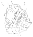
- a vehicle command armrest assembly 10 includes an armrest base unit 12.
- the armrest base unit 12 is preferably part of a vehicle seat assembly so that armrest base unit 12 pivots and moves with the seat (not shown).
- a touchpad and/or display unit 14 Coupled to the armrest base unit 12 is a touchpad and/or display unit 14, a joystick control unit 16 and a command system module (CMS) 18.
- CMS command system module
- Other types of auxiliary units or modules could be attached to the armrest base unit 12.
- the armrest base unit 12 includes a tub 11 and a top cover 13.
- Tub 11 and top cover 13 form an opening 15 in a side portion 20 thereof.
- the side portion 20 of the tub 11 includes a channel member 22 which forms an upwardly opening channel 19 with a bottom surface 24 and sloping side walls 23 and 25.
- the bottom surface 24 includes an elongated slot 26 and a pair of bores 28 and 30 formed therein.
- the channel member 22 is closed at both ends by end walls 27 and 29.
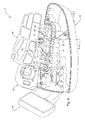
- joystick control unit 16 includes a support or attachment member 32 which is removably received by an end of the channel member 22.
- a pair of threaded bores 34 and 36 are formed in a bottom surface of attachment member 32.
- Command system module 18 includes an attachment member 40 which is removably and slidably received by the channel member 22.
- Attachment member 40 includes a plurality of reinforcing ribs 41 which join together at a center portion 43.
- a threaded bore 42 is formed in the center portion 43 of attachment member 40.
- a knob 44 includes a threaded shaft 45 (shown in Fig. 5 ) which extends through the elongated slot 26 and is screwed into the threaded bore 42.
- Bolt 46 extends through elongated slot 26 and is screwed into threaded bore 34.
- Bolt 48 extends through bore 28 and is screwed into threaded bore 36.
- the channel member 22 and the attaching member 40 have V- or U-shaped cross-sectional characteristic so that the attaching member 40 mates or fits snugly into the channel member 22.
- auxiliary units or modules such as the joystick control unit 16 and/or the command system module 18, can be quickly and easily be assembled to the armrest base unit 12, and or interchanged with each other.
- the U- or V-shaped cross-sectional characteristic of channel member 22 allows the command system module 18 to be secured to the armrest base unit 12 by a single screw. With knob 44, this screw can be easily loosened and the command system module 18 can be slid forward or rearward to accommodate different operators in a seat (not shown) and optimize the ergonomic feel and position of the command system module 18.
- the joystick control unit 16 can easily be installed onto the armrest base unit 12 by inserting the attachment member 32 into the channel member 22 and attaching the two screws 46 and 48 from the bottom. No drilling of the channel member 22 is required.
- a joystick wire harness (not shown) may be inserted into the rear of the command system module 18. With this design, the command armrest assembly 10 does not need to be disassembled at all. The operator can easily remove the joystick control unit 16 when it will not be needed for improved ergonomics for the command system module 18.
- the unique shape of the channel member 22 also allows for other attachments (not shown) to be assembled to the armrest base unit 12, such as additional displays, monitors, or controllers that may be needed by the operator.
- additional displays, monitors, or controllers that may be needed by the operator.
- the advantage of mounting these to the command armrest assembly 10 is they are close to the operator and will move when the seat (not shown) is swiveled, so they remain within reach at all times.
- the joystick control unit 16 is now positioned to the side of the armrest base unit 12 and in a position that all operators can keep their elbows on the soft cushion on top of the armrest base unit 12. It is also in a position that the operator can leave the elbow in one position and pivot the arm between the joystick control unit 16 and different control devices on the armrest base unit 12.
Landscapes
- Engineering & Computer Science (AREA)
- Aviation & Aerospace Engineering (AREA)
- Transportation (AREA)
- Mechanical Engineering (AREA)
- Mechanical Control Devices (AREA)
- Passenger Equipment (AREA)
- Seats For Vehicles (AREA)
- Component Parts Of Construction Machinery (AREA)
Applications Claiming Priority (1)
| Application Number | Priority Date | Filing Date | Title |
|---|---|---|---|
| US12/274,888 US7806470B2 (en) | 2008-11-20 | 2008-11-20 | Vehicle command armrest assembly |
Publications (2)
| Publication Number | Publication Date |
|---|---|
| EP2189328A1 true EP2189328A1 (de) | 2010-05-26 |
| EP2189328B1 EP2189328B1 (de) | 2012-03-14 |
Family
ID=41664578
Family Applications (1)
| Application Number | Title | Priority Date | Filing Date |
|---|---|---|---|
| EP09176543A Active EP2189328B1 (de) | 2008-11-20 | 2009-11-19 | Armstützenanordnung für Fahrzeugführung |
Country Status (5)
| Country | Link |
|---|---|
| US (1) | US7806470B2 (de) |
| EP (1) | EP2189328B1 (de) |
| AT (1) | ATE549206T1 (de) |
| BR (1) | BRPI0904565B1 (de) |
| MX (1) | MX2009012449A (de) |
Cited By (1)
| Publication number | Priority date | Publication date | Assignee | Title |
|---|---|---|---|---|
| EP2460681B2 (de) † | 2010-12-03 | 2018-06-13 | Valtra Oy Ab | Fahrerstand eines Nutzfahrzeugs |
Families Citing this family (21)
| Publication number | Priority date | Publication date | Assignee | Title |
|---|---|---|---|---|
| US8714049B2 (en) * | 2011-02-11 | 2014-05-06 | Cnh Industrial America Llc | Adjustable control system |
| USD710785S1 (en) | 2012-08-20 | 2014-08-12 | Cnh Industrial America Llc | Control console for a vehicle |
| USD727246S1 (en) | 2012-08-20 | 2015-04-21 | Cnh Industrial America Llc | Control console |
| USD763779S1 (en) | 2012-08-20 | 2016-08-16 | Cnh Industrial America Llc | Control panel dividers |
| USD748566S1 (en) | 2012-08-20 | 2016-02-02 | Cnh Industrial America Llc | Control console for a vehicle |
| DE102013012176A1 (de) * | 2013-07-22 | 2015-01-22 | Jungheinrich Aktiengesellschaft | Bedienelement für ein Flurförderzeug |
| DE102014108322A1 (de) | 2014-06-13 | 2015-12-17 | Amazonen-Werke H. Dreyer Gmbh & Co. Kg | Anordnung von Bedien- und/oder Anzeigeelementen |
| USD758284S1 (en) * | 2014-07-22 | 2016-06-07 | ET Works, LLC | Vehicle control interface |
| USD725581S1 (en) * | 2014-07-22 | 2015-03-31 | ET Works, LLC | Vehicle console portion |
| JP6247174B2 (ja) * | 2014-08-01 | 2017-12-13 | 株式会社クボタ | 運転支援システム |
| CN104285593B (zh) * | 2014-08-26 | 2016-11-30 | 浙江亚特电器有限公司 | 一种采棉机的驾驶室 |
| BR112017025504A2 (pt) | 2015-07-17 | 2018-08-07 | Crown Equipment Corporation | dispositivo de processamento tendo uma interface gráfica de usuário. |
| EP3653564B1 (de) | 2016-02-05 | 2022-04-06 | Crown Equipment Corporation | Steuerungselemente für materialhandhabungsfahrzeuge |
| EP3545398B1 (de) | 2016-11-22 | 2023-01-04 | Crown Equipment Corporation | Benutzerschnittstellevorrichtung für ein nutzfahrzeug |
| US10434914B2 (en) * | 2017-03-13 | 2019-10-08 | Cnh Industrial America Llc | Armrest system for holding monitors in an operator cab |
| USD844514S1 (en) * | 2017-07-26 | 2019-04-02 | Deere & Company | Multi-functional joystick for an agricultural vehicle |
| WO2019131721A1 (ja) * | 2017-12-27 | 2019-07-04 | 株式会社クボタ | 作業機及び作業機の製造方法 |
| USD945493S1 (en) * | 2018-03-13 | 2022-03-08 | J.C. Bamford Excavators Limited | Vehicle console |
| GB2579075B (en) * | 2018-11-19 | 2021-06-16 | Caterpillar Inc | Work machine with sensor enabled user control |
| USD953966S1 (en) * | 2019-11-08 | 2022-06-07 | Kubota Corporation | Armrest for tractors |
| US12536860B2 (en) * | 2020-08-18 | 2026-01-27 | T3 Micro, Inc. | Autonomous food station |
Citations (3)
| Publication number | Priority date | Publication date | Assignee | Title |
|---|---|---|---|---|
| US20040133322A1 (en) * | 2003-01-06 | 2004-07-08 | Chernoff Adrian B. | Pivoting arm driver control input device |
| DE102005023890A1 (de) * | 2004-05-25 | 2005-12-22 | Kabushiki Kaisha Toyota Jidoshokki, Kariya | Positionseinstellmechanismus für Fahrzeugarmlehnen |
| US20060042857A1 (en) * | 2004-08-31 | 2006-03-02 | Caterpillar Inc. | Work machine control pedestal |
Family Cites Families (15)
| Publication number | Priority date | Publication date | Assignee | Title |
|---|---|---|---|---|
| US4351562A (en) * | 1980-07-17 | 1982-09-28 | Twitchell Brent L | Movable seat for a motorized transport chair |
| ZA866246B (en) * | 1985-08-27 | 1987-04-29 | Mim Holdings Ltd | Bi-directional vehicle control station |
| US5076524A (en) * | 1990-12-27 | 1991-12-31 | Sony Trans Com, Inc. | TV/LCD pop-up stowage retraction means |
| US5311302A (en) * | 1992-07-02 | 1994-05-10 | Hughes Aircraft Company | Entertainment and data management system for passenger vehicle including individual seat interactive video terminals |
| US5335142A (en) * | 1992-12-21 | 1994-08-02 | Ast Research, Inc. | Portable computer display tilt/swivel mechanism |
| US5409079A (en) * | 1993-12-17 | 1995-04-25 | Ford New Holland, Inc. | Independently movable control console for tractors |
| KR980009677A (ko) * | 1996-07-31 | 1998-04-30 | 김무 | 중장비용 안전레버장치 |
| US6039141A (en) * | 1998-02-23 | 2000-03-21 | Case Corporation | Moving operator and display unit |
| US6089663A (en) * | 1999-02-05 | 2000-07-18 | Spang & Company | Video game accessory chair apparatus |
| AT407003B (de) * | 1999-04-12 | 2000-11-27 | Sdm Hansen Ag | Armauflage für ein sitzmöbel |
| DE29908103U1 (de) * | 1999-05-06 | 1999-07-22 | Hu, Jung-Hua, Tainan Hsien | Bewegungsvorrichtung für eine Armlehne |
| US6715269B2 (en) * | 2002-07-17 | 2004-04-06 | Cnh America Llc | Adjustable monitor mount |
| US6908158B2 (en) * | 2003-01-02 | 2005-06-21 | Haworth, Inc. | Lateral motion chair arm mechanism for chair arm |
| US6814174B2 (en) * | 2003-01-23 | 2004-11-09 | Ingersoll-Rand Company | Telescoping seat assembly for a construction vehicle |
| US7121608B2 (en) * | 2004-09-23 | 2006-10-17 | Crown Equipment Corporation | Rotating and/or swiveling seat |
-
2008
- 2008-11-20 US US12/274,888 patent/US7806470B2/en not_active Expired - Fee Related
-
2009
- 2009-11-18 BR BRPI0904565-1A patent/BRPI0904565B1/pt not_active IP Right Cessation
- 2009-11-18 MX MX2009012449A patent/MX2009012449A/es active IP Right Grant
- 2009-11-19 AT AT09176543T patent/ATE549206T1/de active
- 2009-11-19 EP EP09176543A patent/EP2189328B1/de active Active
Patent Citations (3)
| Publication number | Priority date | Publication date | Assignee | Title |
|---|---|---|---|---|
| US20040133322A1 (en) * | 2003-01-06 | 2004-07-08 | Chernoff Adrian B. | Pivoting arm driver control input device |
| DE102005023890A1 (de) * | 2004-05-25 | 2005-12-22 | Kabushiki Kaisha Toyota Jidoshokki, Kariya | Positionseinstellmechanismus für Fahrzeugarmlehnen |
| US20060042857A1 (en) * | 2004-08-31 | 2006-03-02 | Caterpillar Inc. | Work machine control pedestal |
Cited By (1)
| Publication number | Priority date | Publication date | Assignee | Title |
|---|---|---|---|---|
| EP2460681B2 (de) † | 2010-12-03 | 2018-06-13 | Valtra Oy Ab | Fahrerstand eines Nutzfahrzeugs |
Also Published As
| Publication number | Publication date |
|---|---|
| US7806470B2 (en) | 2010-10-05 |
| BRPI0904565A2 (pt) | 2011-03-15 |
| BRPI0904565B1 (pt) | 2019-04-02 |
| ATE549206T1 (de) | 2012-03-15 |
| MX2009012449A (es) | 2010-05-25 |
| US20100123345A1 (en) | 2010-05-20 |
| EP2189328B1 (de) | 2012-03-14 |
Similar Documents
| Publication | Publication Date | Title |
|---|---|---|
| EP2189328B1 (de) | Armstützenanordnung für Fahrzeugführung | |
| EP2179093B1 (de) | Baumaschine mit einem führerhaus mit fortschrittlicher ergonomie | |
| US20030230447A1 (en) | Operator control station for controlling different work machines | |
| KR101789847B1 (ko) | 차량 변속기용 모듈형 작동 장치 | |
| US20130092858A1 (en) | Upper machine body for operating machine, and operating machine having the same | |
| EP3815966A1 (de) | Nutzfahrzeug | |
| CA2411180A1 (en) | Adjustable support assembly for a data entry/interface device for computers or the like | |
| US20200240109A1 (en) | Adjustable operator console for machine control | |
| CN108473291B (zh) | 材料处理车辆的控制元件 | |
| AU2018206784A1 (en) | Power transfer seat | |
| US20160130782A1 (en) | Motor Grader Implement Valve Layout for Narrow Front Cab | |
| JP2006230353A (ja) | コンバイン | |
| JP2008161203A (ja) | コンバイン | |
| EP4474194B1 (de) | Haltevorrichtung in einem fahrzeug für ein eingabegerät mit einer anzeige | |
| US20140020497A1 (en) | Adjustable Pod Support for Machine Control Device | |
| JP2001055759A (ja) | 建設機械の運転操縦装置 | |
| JP5065473B2 (ja) | 建設機械のアームレスト装置 | |
| US20160130783A1 (en) | Motor Grader Implement Valve Layout for Narrow Front Cab | |
| US11124092B2 (en) | Transfer seat and method | |
| CN211075621U (zh) | 一种座椅安装支架及工程设备 | |
| CN217705579U (zh) | 扶手组件及作业机械 | |
| DE102024101324B4 (de) | Schalttafelanordnung für ein Kraftfahrzeug und Kraftfahrzeug | |
| JP4400627B2 (ja) | コンバイン | |
| JP2009270270A (ja) | スイッチ装置 | |
| JP2005290928A (ja) | 建設機械用キャブ |
Legal Events
| Date | Code | Title | Description |
|---|---|---|---|
| PUAI | Public reference made under article 153(3) epc to a published international application that has entered the european phase |
Free format text: ORIGINAL CODE: 0009012 |
|
| AK | Designated contracting states |
Kind code of ref document: A1 Designated state(s): AT BE BG CH CY CZ DE DK EE ES FI FR GB GR HR HU IE IS IT LI LT LU LV MC MK MT NL NO PL PT RO SE SI SK SM TR |
|
| 17P | Request for examination filed |
Effective date: 20101126 |
|
| 17Q | First examination report despatched |
Effective date: 20110120 |
|
| RIC1 | Information provided on ipc code assigned before grant |
Ipc: B60N 2/46 20060101AFI20110531BHEP |
|
| GRAP | Despatch of communication of intention to grant a patent |
Free format text: ORIGINAL CODE: EPIDOSNIGR1 |
|
| GRAS | Grant fee paid |
Free format text: ORIGINAL CODE: EPIDOSNIGR3 |
|
| GRAA | (expected) grant |
Free format text: ORIGINAL CODE: 0009210 |
|
| AK | Designated contracting states |
Kind code of ref document: B1 Designated state(s): AT BE BG CH CY CZ DE DK EE ES FI FR GB GR HR HU IE IS IT LI LT LU LV MC MK MT NL NO PL PT RO SE SI SK SM TR |
|
| REG | Reference to a national code |
Ref country code: GB Ref legal event code: FG4D |
|
| REG | Reference to a national code |
Ref country code: AT Ref legal event code: REF Ref document number: 549206 Country of ref document: AT Kind code of ref document: T Effective date: 20120315 Ref country code: CH Ref legal event code: EP |
|
| REG | Reference to a national code |
Ref country code: IE Ref legal event code: FG4D |
|
| REG | Reference to a national code |
Ref country code: DE Ref legal event code: R096 Ref document number: 602009005875 Country of ref document: DE Effective date: 20120510 |
|
| REG | Reference to a national code |
Ref country code: NL Ref legal event code: VDEP Effective date: 20120314 |
|
| PG25 | Lapsed in a contracting state [announced via postgrant information from national office to epo] |
Ref country code: NO Free format text: LAPSE BECAUSE OF FAILURE TO SUBMIT A TRANSLATION OF THE DESCRIPTION OR TO PAY THE FEE WITHIN THE PRESCRIBED TIME-LIMIT Effective date: 20120614 Ref country code: LT Free format text: LAPSE BECAUSE OF FAILURE TO SUBMIT A TRANSLATION OF THE DESCRIPTION OR TO PAY THE FEE WITHIN THE PRESCRIBED TIME-LIMIT Effective date: 20120314 Ref country code: HR Free format text: LAPSE BECAUSE OF FAILURE TO SUBMIT A TRANSLATION OF THE DESCRIPTION OR TO PAY THE FEE WITHIN THE PRESCRIBED TIME-LIMIT Effective date: 20120314 |
|
| LTIE | Lt: invalidation of european patent or patent extension |
Effective date: 20120314 |
|
| PG25 | Lapsed in a contracting state [announced via postgrant information from national office to epo] |
Ref country code: LV Free format text: LAPSE BECAUSE OF FAILURE TO SUBMIT A TRANSLATION OF THE DESCRIPTION OR TO PAY THE FEE WITHIN THE PRESCRIBED TIME-LIMIT Effective date: 20120314 Ref country code: FI Free format text: LAPSE BECAUSE OF FAILURE TO SUBMIT A TRANSLATION OF THE DESCRIPTION OR TO PAY THE FEE WITHIN THE PRESCRIBED TIME-LIMIT Effective date: 20120314 Ref country code: GR Free format text: LAPSE BECAUSE OF FAILURE TO SUBMIT A TRANSLATION OF THE DESCRIPTION OR TO PAY THE FEE WITHIN THE PRESCRIBED TIME-LIMIT Effective date: 20120615 |
|
| REG | Reference to a national code |
Ref country code: AT Ref legal event code: MK05 Ref document number: 549206 Country of ref document: AT Kind code of ref document: T Effective date: 20120314 |
|
| PG25 | Lapsed in a contracting state [announced via postgrant information from national office to epo] |
Ref country code: CY Free format text: LAPSE BECAUSE OF FAILURE TO SUBMIT A TRANSLATION OF THE DESCRIPTION OR TO PAY THE FEE WITHIN THE PRESCRIBED TIME-LIMIT Effective date: 20120314 |
|
| PG25 | Lapsed in a contracting state [announced via postgrant information from national office to epo] |
Ref country code: BE Free format text: LAPSE BECAUSE OF FAILURE TO SUBMIT A TRANSLATION OF THE DESCRIPTION OR TO PAY THE FEE WITHIN THE PRESCRIBED TIME-LIMIT Effective date: 20120314 Ref country code: RO Free format text: LAPSE BECAUSE OF FAILURE TO SUBMIT A TRANSLATION OF THE DESCRIPTION OR TO PAY THE FEE WITHIN THE PRESCRIBED TIME-LIMIT Effective date: 20120314 Ref country code: IS Free format text: LAPSE BECAUSE OF FAILURE TO SUBMIT A TRANSLATION OF THE DESCRIPTION OR TO PAY THE FEE WITHIN THE PRESCRIBED TIME-LIMIT Effective date: 20120714 Ref country code: EE Free format text: LAPSE BECAUSE OF FAILURE TO SUBMIT A TRANSLATION OF THE DESCRIPTION OR TO PAY THE FEE WITHIN THE PRESCRIBED TIME-LIMIT Effective date: 20120314 Ref country code: PL Free format text: LAPSE BECAUSE OF FAILURE TO SUBMIT A TRANSLATION OF THE DESCRIPTION OR TO PAY THE FEE WITHIN THE PRESCRIBED TIME-LIMIT Effective date: 20120314 Ref country code: SE Free format text: LAPSE BECAUSE OF FAILURE TO SUBMIT A TRANSLATION OF THE DESCRIPTION OR TO PAY THE FEE WITHIN THE PRESCRIBED TIME-LIMIT Effective date: 20120314 Ref country code: CZ Free format text: LAPSE BECAUSE OF FAILURE TO SUBMIT A TRANSLATION OF THE DESCRIPTION OR TO PAY THE FEE WITHIN THE PRESCRIBED TIME-LIMIT Effective date: 20120314 Ref country code: SI Free format text: LAPSE BECAUSE OF FAILURE TO SUBMIT A TRANSLATION OF THE DESCRIPTION OR TO PAY THE FEE WITHIN THE PRESCRIBED TIME-LIMIT Effective date: 20120314 |
|
| PG25 | Lapsed in a contracting state [announced via postgrant information from national office to epo] |
Ref country code: SK Free format text: LAPSE BECAUSE OF FAILURE TO SUBMIT A TRANSLATION OF THE DESCRIPTION OR TO PAY THE FEE WITHIN THE PRESCRIBED TIME-LIMIT Effective date: 20120314 Ref country code: PT Free format text: LAPSE BECAUSE OF FAILURE TO SUBMIT A TRANSLATION OF THE DESCRIPTION OR TO PAY THE FEE WITHIN THE PRESCRIBED TIME-LIMIT Effective date: 20120716 |
|
| PLBE | No opposition filed within time limit |
Free format text: ORIGINAL CODE: 0009261 |
|
| STAA | Information on the status of an ep patent application or granted ep patent |
Free format text: STATUS: NO OPPOSITION FILED WITHIN TIME LIMIT |
|
| PG25 | Lapsed in a contracting state [announced via postgrant information from national office to epo] |
Ref country code: DK Free format text: LAPSE BECAUSE OF FAILURE TO SUBMIT A TRANSLATION OF THE DESCRIPTION OR TO PAY THE FEE WITHIN THE PRESCRIBED TIME-LIMIT Effective date: 20120314 Ref country code: AT Free format text: LAPSE BECAUSE OF FAILURE TO SUBMIT A TRANSLATION OF THE DESCRIPTION OR TO PAY THE FEE WITHIN THE PRESCRIBED TIME-LIMIT Effective date: 20120314 Ref country code: NL Free format text: LAPSE BECAUSE OF FAILURE TO SUBMIT A TRANSLATION OF THE DESCRIPTION OR TO PAY THE FEE WITHIN THE PRESCRIBED TIME-LIMIT Effective date: 20120314 |
|
| 26N | No opposition filed |
Effective date: 20121217 |
|
| REG | Reference to a national code |
Ref country code: DE Ref legal event code: R097 Ref document number: 602009005875 Country of ref document: DE Effective date: 20121217 |
|
| PG25 | Lapsed in a contracting state [announced via postgrant information from national office to epo] |
Ref country code: ES Free format text: LAPSE BECAUSE OF FAILURE TO SUBMIT A TRANSLATION OF THE DESCRIPTION OR TO PAY THE FEE WITHIN THE PRESCRIBED TIME-LIMIT Effective date: 20120625 |
|
| PG25 | Lapsed in a contracting state [announced via postgrant information from national office to epo] |
Ref country code: BG Free format text: LAPSE BECAUSE OF FAILURE TO SUBMIT A TRANSLATION OF THE DESCRIPTION OR TO PAY THE FEE WITHIN THE PRESCRIBED TIME-LIMIT Effective date: 20120614 |
|
| REG | Reference to a national code |
Ref country code: IE Ref legal event code: MM4A |
|
| PG25 | Lapsed in a contracting state [announced via postgrant information from national office to epo] |
Ref country code: IE Free format text: LAPSE BECAUSE OF NON-PAYMENT OF DUE FEES Effective date: 20121119 |
|
| PG25 | Lapsed in a contracting state [announced via postgrant information from national office to epo] |
Ref country code: MT Free format text: LAPSE BECAUSE OF FAILURE TO SUBMIT A TRANSLATION OF THE DESCRIPTION OR TO PAY THE FEE WITHIN THE PRESCRIBED TIME-LIMIT Effective date: 20120314 |
|
| PG25 | Lapsed in a contracting state [announced via postgrant information from national office to epo] |
Ref country code: MC Free format text: LAPSE BECAUSE OF NON-PAYMENT OF DUE FEES Effective date: 20121130 Ref country code: TR Free format text: LAPSE BECAUSE OF FAILURE TO SUBMIT A TRANSLATION OF THE DESCRIPTION OR TO PAY THE FEE WITHIN THE PRESCRIBED TIME-LIMIT Effective date: 20120314 |
|
| PG25 | Lapsed in a contracting state [announced via postgrant information from national office to epo] |
Ref country code: SM Free format text: LAPSE BECAUSE OF FAILURE TO SUBMIT A TRANSLATION OF THE DESCRIPTION OR TO PAY THE FEE WITHIN THE PRESCRIBED TIME-LIMIT Effective date: 20120314 Ref country code: LU Free format text: LAPSE BECAUSE OF NON-PAYMENT OF DUE FEES Effective date: 20121119 |
|
| REG | Reference to a national code |
Ref country code: CH Ref legal event code: PL |
|
| PG25 | Lapsed in a contracting state [announced via postgrant information from national office to epo] |
Ref country code: LI Free format text: LAPSE BECAUSE OF NON-PAYMENT OF DUE FEES Effective date: 20131130 Ref country code: HU Free format text: LAPSE BECAUSE OF FAILURE TO SUBMIT A TRANSLATION OF THE DESCRIPTION OR TO PAY THE FEE WITHIN THE PRESCRIBED TIME-LIMIT Effective date: 20091119 Ref country code: CH Free format text: LAPSE BECAUSE OF NON-PAYMENT OF DUE FEES Effective date: 20131130 |
|
| PG25 | Lapsed in a contracting state [announced via postgrant information from national office to epo] |
Ref country code: MK Free format text: LAPSE BECAUSE OF FAILURE TO SUBMIT A TRANSLATION OF THE DESCRIPTION OR TO PAY THE FEE WITHIN THE PRESCRIBED TIME-LIMIT Effective date: 20120314 |
|
| REG | Reference to a national code |
Ref country code: FR Ref legal event code: PLFP Year of fee payment: 7 |
|
| REG | Reference to a national code |
Ref country code: FR Ref legal event code: PLFP Year of fee payment: 8 |
|
| PGFP | Annual fee paid to national office [announced via postgrant information from national office to epo] |
Ref country code: IT Payment date: 20161124 Year of fee payment: 8 |
|
| REG | Reference to a national code |
Ref country code: FR Ref legal event code: PLFP Year of fee payment: 9 |
|
| REG | Reference to a national code |
Ref country code: DE Ref legal event code: R079 Ref document number: 602009005875 Country of ref document: DE Free format text: PREVIOUS MAIN CLASS: B60N0002460000 Ipc: B60N0002750000 |
|
| PGFP | Annual fee paid to national office [announced via postgrant information from national office to epo] |
Ref country code: FR Payment date: 20171127 Year of fee payment: 9 |
|
| PGFP | Annual fee paid to national office [announced via postgrant information from national office to epo] |
Ref country code: GB Payment date: 20171127 Year of fee payment: 9 |
|
| PG25 | Lapsed in a contracting state [announced via postgrant information from national office to epo] |
Ref country code: IT Free format text: LAPSE BECAUSE OF NON-PAYMENT OF DUE FEES Effective date: 20171119 |
|
| GBPC | Gb: european patent ceased through non-payment of renewal fee |
Effective date: 20181119 |
|
| PG25 | Lapsed in a contracting state [announced via postgrant information from national office to epo] |
Ref country code: FR Free format text: LAPSE BECAUSE OF NON-PAYMENT OF DUE FEES Effective date: 20181130 |
|
| PG25 | Lapsed in a contracting state [announced via postgrant information from national office to epo] |
Ref country code: GB Free format text: LAPSE BECAUSE OF NON-PAYMENT OF DUE FEES Effective date: 20181119 |
|
| PGFP | Annual fee paid to national office [announced via postgrant information from national office to epo] |
Ref country code: DE Payment date: 20241021 Year of fee payment: 16 |