EP2189672A2 - Lagervorrichtung und Windturbine mit der Lagervorrichtung - Google Patents
Lagervorrichtung und Windturbine mit der Lagervorrichtung Download PDFInfo
- Publication number
- EP2189672A2 EP2189672A2 EP09176295A EP09176295A EP2189672A2 EP 2189672 A2 EP2189672 A2 EP 2189672A2 EP 09176295 A EP09176295 A EP 09176295A EP 09176295 A EP09176295 A EP 09176295A EP 2189672 A2 EP2189672 A2 EP 2189672A2
- Authority
- EP
- European Patent Office
- Prior art keywords
- bearing device
- main shaft
- cylindrical portion
- hollow
- wind turbine
- Prior art date
- Legal status (The legal status is an assumption and is not a legal conclusion. Google has not performed a legal analysis and makes no representation as to the accuracy of the status listed.)
- Withdrawn
Links
- 239000012530 fluid Substances 0.000 claims abstract description 58
- 230000001050 lubricating effect Effects 0.000 claims abstract description 27
- 239000000463 material Substances 0.000 claims description 14
- 230000005684 electric field Effects 0.000 claims description 9
- 229910000897 Babbitt (metal) Inorganic materials 0.000 claims description 5
- 229910000906 Bronze Inorganic materials 0.000 claims description 5
- OAICVXFJPJFONN-UHFFFAOYSA-N Phosphorus Chemical compound [P] OAICVXFJPJFONN-UHFFFAOYSA-N 0.000 claims description 5
- 229910001361 White metal Inorganic materials 0.000 claims description 5
- 239000010974 bronze Substances 0.000 claims description 5
- 239000002131 composite material Substances 0.000 claims description 5
- KUNSUQLRTQLHQQ-UHFFFAOYSA-N copper tin Chemical compound [Cu].[Sn] KUNSUQLRTQLHQQ-UHFFFAOYSA-N 0.000 claims description 5
- 239000004519 grease Substances 0.000 claims description 5
- 239000010969 white metal Substances 0.000 claims description 5
- 239000000314 lubricant Substances 0.000 description 6
- 238000005452 bending Methods 0.000 description 4
- 238000012986 modification Methods 0.000 description 3
- 230000004048 modification Effects 0.000 description 3
- 230000007613 environmental effect Effects 0.000 description 2
- 229910052796 boron Inorganic materials 0.000 description 1
- 238000000576 coating method Methods 0.000 description 1
- 230000001419 dependent effect Effects 0.000 description 1
- 238000005461 lubrication Methods 0.000 description 1
- 239000002184 metal Substances 0.000 description 1
- 229920013639 polyalphaolefin Polymers 0.000 description 1
Images


Classifications
-
- F—MECHANICAL ENGINEERING; LIGHTING; HEATING; WEAPONS; BLASTING
- F16—ENGINEERING ELEMENTS AND UNITS; GENERAL MEASURES FOR PRODUCING AND MAINTAINING EFFECTIVE FUNCTIONING OF MACHINES OR INSTALLATIONS; THERMAL INSULATION IN GENERAL
- F16C—SHAFTS; FLEXIBLE SHAFTS; ELEMENTS OR CRANKSHAFT MECHANISMS; ROTARY BODIES OTHER THAN GEARING ELEMENTS; BEARINGS
- F16C33/00—Parts of bearings; Special methods for making bearings or parts thereof
- F16C33/02—Parts of sliding-contact bearings
- F16C33/04—Brasses; Bushes; Linings
- F16C33/06—Sliding surface mainly made of metal
- F16C33/10—Construction relative to lubrication
- F16C33/1025—Construction relative to lubrication with liquid, e.g. oil, as lubricant
- F16C33/109—Lubricant compositions or properties, e.g. viscosity
-
- F—MECHANICAL ENGINEERING; LIGHTING; HEATING; WEAPONS; BLASTING
- F16—ENGINEERING ELEMENTS AND UNITS; GENERAL MEASURES FOR PRODUCING AND MAINTAINING EFFECTIVE FUNCTIONING OF MACHINES OR INSTALLATIONS; THERMAL INSULATION IN GENERAL
- F16C—SHAFTS; FLEXIBLE SHAFTS; ELEMENTS OR CRANKSHAFT MECHANISMS; ROTARY BODIES OTHER THAN GEARING ELEMENTS; BEARINGS
- F16C17/00—Sliding-contact bearings for exclusively rotary movement
- F16C17/02—Sliding-contact bearings for exclusively rotary movement for radial load only
-
- F—MECHANICAL ENGINEERING; LIGHTING; HEATING; WEAPONS; BLASTING
- F16—ENGINEERING ELEMENTS AND UNITS; GENERAL MEASURES FOR PRODUCING AND MAINTAINING EFFECTIVE FUNCTIONING OF MACHINES OR INSTALLATIONS; THERMAL INSULATION IN GENERAL
- F16C—SHAFTS; FLEXIBLE SHAFTS; ELEMENTS OR CRANKSHAFT MECHANISMS; ROTARY BODIES OTHER THAN GEARING ELEMENTS; BEARINGS
- F16C2360/00—Engines or pumps
- F16C2360/31—Wind motors
Definitions
- the present disclosure generally relates to wind turbines including a drive train having at least one rotor with at least one rotor blade attached to a hub, and especially relates to an apparatus for rotatably supporting a main shaft of a drive train of a wind turbine.
- the present disclosure relates to the design and arrangement of bearings adapted for supporting the main shaft of the wind turbine.
- Wind turbines are of increasing importance as an environmentally safe and relatively inexpensive energy source.
- an increased demand for an improved wind turbine performance has led to efforts concerning an energy-efficient bearing of a main shaft of a wind turbine.
- Bearing devices for such kind of main shafts may include complex lubrication systems.
- the main shaft of a wind turbine has a large diameter and rotates at a relatively low speed.
- Torque applied at the main shaft of a wind turbine can be relatively high in order to transfer wind energy from the rotor towards a speed adapter, e.g. a gearbox of the wind turbine.
- a bearing device for a main shaft of a wind turbine including a fixed hollow-cylindrical portion adapted for being mounted at a machine nacelle of the wind turbine, wherein an inner diameter of the hollow-cylindrical portion is larger than the outer diameter of the main shaft such that a cavity is formed therebetween when the main shaft is inserted into the hollow-cylindrical portion, and a fitting adapted to provide a lubricating fluid to the cavity between the fixed hollow-cylindrical portion and the main shaft.
- a bearing device for a hub of a wind turbine including a protruding portion adapted for being mounted at a main frame of a machine nacelle of the wind turbine, a rotatable hollow-cylindrical portion adapted for being connected to the hub, wherein an inner diameter of the rotatable hollow-cylindrical portion is larger than an outer diameter of the protruding portion such that a cavity is formed therebetween when the protruding portion is inserted into the rotatable hollow-cylindrical portion and a fitting adapted to provide a lubricating fluid to the cavity between the protruding portion and the rotatable hollow-cylindrical portion.
- Fig. 1 is a schematic view of a wind turbine 100 having a machine nacelle 103, which is rotatably mounted on top of a tower 102.
- the wind turbine 100 further includes a rotor having a hub 104 and at least one rotor blade 101.
- the hub 104 is the central part of the rotor, and the at least one rotor blade 101 extends outwardly from the hub.
- wind turbine 100 illustrated in Fig. 1 includes three rotor blades 101, any number of rotor blades 101 may be provided.
- the nacelle 103 which is located on top of the tower 102 can be rotated about a central axis, e.g. a vertical axis 107 of the tower 102.
- the orientation of the machine nacelle 103 with respect to the central axis of the tower 102 is referred to as a yaw angle 106.
- the yaw angle 106 is adjusted such that an axis of the main shaft 112 of the drive train of the wind turbine is typically directed towards an incoming wind direction 105.
- the at least one rotor blade 101 may be adjusted with respect to its longitudinal axis such that a pitch angle 108 of the rotor blade may be adapted to the incoming wind velocity.
- a bending moment 109 may occur due to a vertical wind shear such that the main shaft 112 of the wind turbine experiences a bending force.
- the main shaft 112 of the wind turbine mechanically connects the hub 104 to a gearbox 111 such that a rotational momentum provided by the wind energy may be transferred to the gearbox 111 and further on to an electrical generator (not shown in Fig. 1 ) for the generation of electric energy.
- a magnetic speed adaptor may be used which does not require any mechanical gearboxes.
- reference numeral 111 denotes a mechanical gearbox which is not detailed in the following description, because the gearbox itself does not contribute to the understanding of the present disclosure.
- a bearing device 200 is provided for rotatably supporting the main shaft 112 of the wind turbine 100.
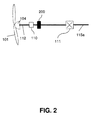
- Fig. 2 is a schematic top view of the wind turbine 100 indicating typical components of the drive train of the wind turbine.
- the at least one rotor blade 101 is attached at the hub 104, wherein the rotation of the hub 104 results in a rotation of the main shaft 112.
- a rotation sensor 110 is provided in order to determine a rotational speed of the main shaft 112.
- the main shaft 112 is supported by the bearing device 200 which will be described in detail hereinafter.
- the main shaft 112 furthermore is connected to the gearbox 111 which transforms a low rotational input speed into a high rotational output speed provided at a gearbox output shaft 115a.
- a drive train of a wind turbine 100 includes the rotor having at least one rotor blade 101 and the hub 104 and the main shaft 112.
- the main shaft 112 is supported by at least one bearing device 200.
- a bearing device 200 according to a typical embodiment is illustrated in Fig. 3 .
- Fig. 3 is a cross-section of a main shaft 112 of a wind turbine 100 at the location of a bearing device 200.
- the bearing device 200 according to the typical embodiment shown in Fig. 3 includes a fixed hollow-cylindrical portion 202 used as a housing which has a fitting 203.
- the fitting 203 is adapted for inserting a high-viscosity fluid into the interior of the housing 202.
- the main shaft 112 is supported rotatably.
- a reference numeral 113 denotes a rotation axis of the main shaft 112.
- the housing 203 may be formed as a hollow-cylindrical portion having end covers in order to prevent the fluid leakage.
- a high-viscosity fluid is distributed within a cavity 204 between the main shaft 112 and an inner wall of the housing 202.
- a frictionless environment is provided in order to support and guide the rotating main shaft 112.
- Typical journal bearings 200 exhibit a long lifetime as compared to conventional roller bearings.
- the housing 202 is provided as a cylinder surrounding the main shaft 112 wherein the cavity 204 between the outer surface of the main shaft 112 and the inner surface of the housing 202 is filled with a fluid lubricant, e.g. a high-viscosity oil.
- a fluid lubricant e.g. a high-viscosity oil.
- the main shaft 112 is supported by the fluid lubricant when the main shaft 112 is rotating. Hydrodynamic principles which are active as the main shaft 112 rotates support the main shaft 112 and relocate it within the cavity 204.
- high-viscosity lubricants are filled into the cavity 204 for providing a bearing for slowly rotating main shafts 112 of wind turbines 100.
- Reference numeral 201 in Fig. 3 indicates a rotation direction.
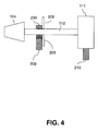
- Fig. 4 is a side view of a drive train of a wind turbine 100, wherein the drive train typically includes the hub 104 and the main shaft 112 which is connected to the hub 104.
- the main shaft 112 furthermore is connected to the gearbox 111 which can be provided as a speed adapter.
- the gear box 111 is supported by a second mounting unit 210 such that one end of the main shaft 112 is supported.
- the other end of the main shaft 112 is supported by a bearing device 200 which is provided as a journal bearing according to a typical embodiment.
- the bearing device 200 is supported by a first mounting unit 209. Both the first mounting unit 209 and the second mounting unit 210 are fixed at a main frame (not shown in Fig. 4 ) of the machine nacelle 103 of the wind turbine 100.
- first mounting unit 209 and the second mounting unit 210 may be provided as elastic supports for the journal bearings in order to absorb extreme loads and/or bending moments explained above.
- a thrust bearing 205 is provided in order to define an axial position of the main shaft 112.
- the thrust bearing 205 may be provided as a conventional roller bearing and/or as a journal bearing.
- journal bearing device 200 may be provided in order to rotatably support the main shaft 112 of the drive train of the wind turbine 100.
- the main shaft 112 is supported, on the left side in Fig. 4 , by the bearing device 200 and on the right side of Fig. 4 , by the gearbox 111.
- Fig. 5 is a side view of a drive train arrangement according to another typical embodiment.
- the drive train includes a hub 104 in the main shaft 112, wherein the main shaft 112 is a connection means between the hub 104 and the gearbox 111.
- two journal bearing devices 200 are provided in order to rotatably support the main shaft 112 of the wind turbine 100.
- the two bearing devices 200 are supported by a first mounting unit 209 and a second mounting unit 210.
- first and second mounting units 209, 210 may be provided as elastic supports in order to absorb extreme loads and/or bending moments from the main shaft 112.
- the gearbox 111 is attached to one side of the main shaft 112.
- thrust bearings 205 which can be provided as journal bearings are used in order to axially define the position of the main shaft 112.
- Materials used for the at least one journal bearing device 200, in particular for the housing 202 of the at least one journal bearing device 200 include, but are not restricted to, white metal, babbit metal, composite material, high performance plastic material and phosphor bronze. According to a further typical embodiment, metal with tailor-made coatings can be applied such as hard-coated nickel-chrome-boron.
- high-performance plastic material can be used between a metallic part and a plastic portion.
- polyalphaolefin having a viscosity of approximately 43,000 cSt that will allow to have the required oil film may be used.
- the outer surface of the main shaft 112 at the location of the journal bearing 200 can be polished. Furthermore, the inner surface of the housing 202 of the journal bearing can have a polished structure.
- the fluid lubricant such as the high-viscosity oil is fed into the cavity 204 of the bearing 200 via the fitting 203 (see Fig. 3 ). The filling of the journal bearing 200 with the fluid lubricant may be performed under high pressure.
- Fig. 6 is a cross-sectional view of a journal bearing 200 according to yet another typical embodiment.
- the journal bearing 200 shown in Fig. 6 has a housing 202 and a high-performance plastic material 208 which is attached at the inner wall of the hollow-cylindrical housing 202. Within the high-performance plastic material 208, a cylindrical electrode 207 is embedded.
- Reference numeral 201 in Fig. 3 indicates a rotation direction of the main shaft 112 about the rotation axis 113.
- the cavity 204 between the main shaft 112 and the housing 202 (denoted by a reference numeral 204 in Fig. 3 ) is filled by an electrorheological fluid 206.
- the electrorheological fluid 206 is a fluid the viscosity of which can be controlled by means of an electric field applied across the fluid layer.
- the electrorheological fluid 206 is introduced into the cavity 204 by means of a fitting 203.
- the electrorheological fluid 206 is introduced under high pressure.
- a power supply (not shown) is used in order to apply a potential difference between the electrode 207 and the electrically conducting main shaft 112.
- the viscosity of the electrorheological fluid 206 may be adjusted in accordance with an environmental temperature such that a constant viscosity can be provided for the journal bearing 200 even if environmental temperatures change due to, e.g. summer/winter season.
- the magnetorheological fluid is controllable by means of a magnetic field.
- a magnetically transmitting material has to be provided for the housing 202 of the bearing device 200 in addition to a magnetic field generation means (not shown in the drawings), instead of the electrode configuration 207, 112.
- the magnetic field created in a direct drive can be used for that purpose and the control of the magnetic and/or electric field can be embedded in the control of the generator/converter.
- Fig. 7 is a side sectional view of a drive train of the wind turbine according to yet another typical embodiment.
- a main frame 114 is fixed, whereas the hub 104 together with the at least one rotor blade 101 (not shown in Fig. 7 ) is rotating about a fixed protruding portion 115 of the fixed main frame 114.
- the rotation axis 113 coincides with the central axis of the main shaft 112.
- the protruding portion 115 may be hollow such that the main shaft 112 can be inserted into the protruding portion.
- the main shaft 112 is adapted for rotating within the fixed protruding portion 115 of the fixed main frame 114.
- the support of the hub 104 is provided by journal bearing devices 200 at two axial positions along the fixed protruding portion 115 of the fixed main frame 114.
- the bearing devices may include a fitting 203 adapted to provide a lubricating fluid.
- thrust bearings 205 are provided in order to define an axial position of the rotating hub 104.
- a mechanical connection of the hub 104 to the main shaft 112 is provided by an axis support unit 116.
- main axis 112 can be supported by at least one journal bearing device 200 according to a typical embodiment (see e.g. Fig. 3 .
Landscapes
- Engineering & Computer Science (AREA)
- General Engineering & Computer Science (AREA)
- Mechanical Engineering (AREA)
- Chemical & Material Sciences (AREA)
- Oil, Petroleum & Natural Gas (AREA)
- Sliding-Contact Bearings (AREA)
- Wind Motors (AREA)
Applications Claiming Priority (1)
| Application Number | Priority Date | Filing Date | Title |
|---|---|---|---|
| US12/275,966 US20100129223A1 (en) | 2008-11-21 | 2008-11-21 | Bearing device and wind turbine having said bearing device |
Publications (1)
| Publication Number | Publication Date |
|---|---|
| EP2189672A2 true EP2189672A2 (de) | 2010-05-26 |
Family
ID=41718545
Family Applications (1)
| Application Number | Title | Priority Date | Filing Date |
|---|---|---|---|
| EP09176295A Withdrawn EP2189672A2 (de) | 2008-11-21 | 2009-11-18 | Lagervorrichtung und Windturbine mit der Lagervorrichtung |
Country Status (3)
| Country | Link |
|---|---|
| US (1) | US20100129223A1 (de) |
| EP (1) | EP2189672A2 (de) |
| CN (1) | CN101737272A (de) |
Cited By (8)
| Publication number | Priority date | Publication date | Assignee | Title |
|---|---|---|---|---|
| WO2011138174A1 (de) * | 2010-05-04 | 2011-11-10 | Siemens Aktiengesellschaft | Vorrichtung zur drehlagerung einer welle, insbesondere zur verwendung in einer dampfturbine |
| US8075190B1 (en) | 2010-09-16 | 2011-12-13 | Vestas Wind Systems A/S | Spherical plain bearing pocket arrangement and wind turbine having such a spherical plain bearing |
| WO2012034568A1 (en) | 2010-09-16 | 2012-03-22 | Vestas Wind Systems A/S | Control system for a wind turbine and method of operating a wind turbine based on monitoring a bearing |
| EP2434154A1 (de) * | 2010-09-28 | 2012-03-28 | Siemens Aktiengesellschaft | Windturbinendämpfanordnung |
| US8172531B2 (en) | 2011-01-10 | 2012-05-08 | Vestas Wind Systems A/S | Plain bearing for a wind turbine blade and method of operating a wind turbine having such a plain bearing |
| EP2345791A3 (de) * | 2010-01-14 | 2014-01-29 | Siemens Aktiengesellschaft | Vanadium basierte Hartstoffbeschichtung einer Windkraftanlagenkomponente |
| EP2345812A3 (de) * | 2010-01-14 | 2014-01-29 | Siemens Aktiengesellschaft | Bor basierte Hartstoffbeschichtung einer Windkraftanlagenkomponente |
| US8727728B2 (en) | 2010-09-16 | 2014-05-20 | Vestas Wind Systems A/S | Convertible bearing for a wind turbine and method for operating same |
Families Citing this family (5)
| Publication number | Priority date | Publication date | Assignee | Title |
|---|---|---|---|---|
| US8408335B2 (en) * | 2008-12-03 | 2013-04-02 | Schlumberger Technology Corporation | Drill string with modular motor units |
| GB201307794D0 (en) * | 2013-04-30 | 2013-06-12 | Romax Technology Ltd | Turbine main bearing lubrication |
| NL2018947B1 (en) * | 2017-05-19 | 2018-11-28 | Univ Delft Tech | Bearing device |
| US10677087B2 (en) * | 2018-05-11 | 2020-06-09 | General Electric Company | Support structure for geared turbomachine |
| EP3739207A1 (de) * | 2019-05-16 | 2020-11-18 | Siemens Gamesa Renewable Energy A/S | Lageranordnung für eine windturbine sowie windturbine |
Family Cites Families (9)
| Publication number | Priority date | Publication date | Assignee | Title |
|---|---|---|---|---|
| US3172709A (en) * | 1963-04-29 | 1965-03-09 | Westinghouse Electric Corp | Shaft bearing arrangement |
| US3746410A (en) * | 1971-08-10 | 1973-07-17 | Hatch Ass Ltd | Journal bearing |
| US4264112A (en) * | 1979-08-06 | 1981-04-28 | Lee Controls, Inc. | Floating pillow blocks |
| US4372732A (en) * | 1980-12-29 | 1983-02-08 | Browning Engineering Corporation | Control mechanism for a windmill |
| GB2306583A (en) * | 1995-10-28 | 1997-05-07 | Daewoo Electronics Co Ltd | Lubricated journal bearing assembly |
| US5759011A (en) * | 1996-05-14 | 1998-06-02 | Dresser-Rand Company | Journal bearing assembly |
| US6116784A (en) * | 1999-01-07 | 2000-09-12 | Brotz; Gregory R. | Dampenable bearing |
| WO2005075610A1 (ja) * | 2004-02-09 | 2005-08-18 | Ntn Corporation | グリース、転がり軸受、等速ジョイントおよび転動部品 |
| US7736063B1 (en) * | 2007-07-24 | 2010-06-15 | The United States Of America As Represented By The Secretary Of The Navy | Bearing apparatus having electrorheological fluid lubricant |
-
2008
- 2008-11-21 US US12/275,966 patent/US20100129223A1/en not_active Abandoned
-
2009
- 2009-11-18 EP EP09176295A patent/EP2189672A2/de not_active Withdrawn
- 2009-11-20 CN CN200910246422A patent/CN101737272A/zh active Pending
Cited By (11)
| Publication number | Priority date | Publication date | Assignee | Title |
|---|---|---|---|---|
| EP2345791A3 (de) * | 2010-01-14 | 2014-01-29 | Siemens Aktiengesellschaft | Vanadium basierte Hartstoffbeschichtung einer Windkraftanlagenkomponente |
| EP2345812A3 (de) * | 2010-01-14 | 2014-01-29 | Siemens Aktiengesellschaft | Bor basierte Hartstoffbeschichtung einer Windkraftanlagenkomponente |
| US8690539B2 (en) | 2010-01-14 | 2014-04-08 | Siemens Aktiengesellschaft | Boron-based refractory coating for a wind turbine component |
| WO2011138174A1 (de) * | 2010-05-04 | 2011-11-10 | Siemens Aktiengesellschaft | Vorrichtung zur drehlagerung einer welle, insbesondere zur verwendung in einer dampfturbine |
| US8075190B1 (en) | 2010-09-16 | 2011-12-13 | Vestas Wind Systems A/S | Spherical plain bearing pocket arrangement and wind turbine having such a spherical plain bearing |
| US8079761B1 (en) | 2010-09-16 | 2011-12-20 | Vestas Wind Systems A/S | Cylindrical plain bearing pocket arrangement and wind turbine having such a cylindrical plain bearing |
| WO2012034568A1 (en) | 2010-09-16 | 2012-03-22 | Vestas Wind Systems A/S | Control system for a wind turbine and method of operating a wind turbine based on monitoring a bearing |
| US8727728B2 (en) | 2010-09-16 | 2014-05-20 | Vestas Wind Systems A/S | Convertible bearing for a wind turbine and method for operating same |
| US8734105B2 (en) | 2010-09-16 | 2014-05-27 | Vestas Wind Systems A/S | Control system for a wind turbine and method of operating a wind turbine based on monitoring a bearing |
| EP2434154A1 (de) * | 2010-09-28 | 2012-03-28 | Siemens Aktiengesellschaft | Windturbinendämpfanordnung |
| US8172531B2 (en) | 2011-01-10 | 2012-05-08 | Vestas Wind Systems A/S | Plain bearing for a wind turbine blade and method of operating a wind turbine having such a plain bearing |
Also Published As
| Publication number | Publication date |
|---|---|
| CN101737272A (zh) | 2010-06-16 |
| US20100129223A1 (en) | 2010-05-27 |
Similar Documents
| Publication | Publication Date | Title |
|---|---|---|
| EP2189672A2 (de) | Lagervorrichtung und Windturbine mit der Lagervorrichtung | |
| CA2457032C (en) | Lubrication of a pitch angle adjusting device of a rotor blade of a windmill | |
| CN103782028B (zh) | 直接驱动风力涡轮机 | |
| EP3460238B1 (de) | Windturbine | |
| US9525320B2 (en) | Electromechanical device with included gear stages and internal lubrication system | |
| EP2094562B1 (de) | Selbstschmierender aktuator für rotorsteuerung auf der laufschaufel | |
| CA2739221C (en) | An electromechanical device | |
| CN103967936B (zh) | 轴承以及从轴承泄漏出的润滑剂的收集方法 | |
| US9903347B2 (en) | Wind turbine gearbox | |
| BRPI0808781B1 (pt) | turbina de vento com componentes de transmissão de carga | |
| EP2144341A2 (de) | Bürstenloser Schleifring einer Windenergieanlage und Anordnungsverfahren | |
| ES2906786T3 (es) | Disposición de rodamiento principal compuesto para una turbina eólica | |
| KR101290359B1 (ko) | 전기기계장치 | |
| CN109751207A (zh) | 用于风力涡轮机的轴承的润滑系统和方法及传动系组件 | |
| EP2913519B1 (de) | Windturbinenenergieerzeugungsvorrichtung | |
| KR20100080007A (ko) | 회전 하우징을 갖는 풍력발전기용 기어박스 | |
| CN119895145B (zh) | 用于风力涡轮机变桨管的轴承组件、相关传动系、风力发电机组及数据聚集体 | |
| CN113864141A (zh) | 用于风力涡轮机的偏航轴承 | |
| RU2368797C2 (ru) | Гидроэнергетическая установка | |
| CN210423664U (zh) | 风电增速箱组合式轴承减震支撑结构 | |
| EP2884102B1 (de) | Getriebe für eine Windkraftanlage | |
| US20180010584A1 (en) | Wind turbine |
Legal Events
| Date | Code | Title | Description |
|---|---|---|---|
| PUAI | Public reference made under article 153(3) epc to a published international application that has entered the european phase |
Free format text: ORIGINAL CODE: 0009012 |
|
| AK | Designated contracting states |
Kind code of ref document: A2 Designated state(s): AT BE BG CH CY CZ DE DK EE ES FI FR GB GR HR HU IE IS IT LI LT LU LV MC MK MT NL NO PL PT RO SE SI SK SM TR |
|
| AX | Request for extension of the european patent |
Extension state: AL BA RS |
|
| STAA | Information on the status of an ep patent application or granted ep patent |
Free format text: STATUS: THE APPLICATION IS DEEMED TO BE WITHDRAWN |
|
| 18D | Application deemed to be withdrawn |
Effective date: 20130601 |