EP2094562B1 - Selbstschmierender aktuator für rotorsteuerung auf der laufschaufel - Google Patents
Selbstschmierender aktuator für rotorsteuerung auf der laufschaufel Download PDFInfo
- Publication number
- EP2094562B1 EP2094562B1 EP07875042.9A EP07875042A EP2094562B1 EP 2094562 B1 EP2094562 B1 EP 2094562B1 EP 07875042 A EP07875042 A EP 07875042A EP 2094562 B1 EP2094562 B1 EP 2094562B1
- Authority
- EP
- European Patent Office
- Prior art keywords
- actuator
- internal cavity
- output rod
- housing
- seal
- Prior art date
- Legal status (The legal status is an assumption and is not a legal conclusion. Google has not performed a legal analysis and makes no representation as to the accuracy of the status listed.)
- Not-in-force
Links
- 230000005540 biological transmission Effects 0.000 claims description 24
- 238000005461 lubrication Methods 0.000 claims description 11
- 230000001050 lubricating effect Effects 0.000 claims description 3
- 239000003921 oil Substances 0.000 description 46
- 239000004519 grease Substances 0.000 description 7
- 239000002609 medium Substances 0.000 description 3
- 230000032258 transport Effects 0.000 description 3
- 230000008859 change Effects 0.000 description 2
- 239000012530 fluid Substances 0.000 description 2
- 230000007246 mechanism Effects 0.000 description 2
- 230000009471 action Effects 0.000 description 1
- 230000001419 dependent effect Effects 0.000 description 1
- 230000000694 effects Effects 0.000 description 1
- 238000007654 immersion Methods 0.000 description 1
- 239000000314 lubricant Substances 0.000 description 1
- 239000010687 lubricating oil Substances 0.000 description 1
- 239000000463 material Substances 0.000 description 1
- 239000007769 metal material Substances 0.000 description 1
- 238000012986 modification Methods 0.000 description 1
- 230000004048 modification Effects 0.000 description 1
- 230000002035 prolonged effect Effects 0.000 description 1
- 230000001737 promoting effect Effects 0.000 description 1
- 238000007789 sealing Methods 0.000 description 1
- 239000006163 transport media Substances 0.000 description 1
- UONOETXJSWQNOL-UHFFFAOYSA-N tungsten carbide Chemical compound [W+]#[C-] UONOETXJSWQNOL-UHFFFAOYSA-N 0.000 description 1
Images


Classifications
-
- B—PERFORMING OPERATIONS; TRANSPORTING
- B64—AIRCRAFT; AVIATION; COSMONAUTICS
- B64C—AEROPLANES; HELICOPTERS
- B64C27/00—Rotorcraft; Rotors peculiar thereto
- B64C27/54—Mechanisms for controlling blade adjustment or movement relative to rotor head, e.g. lag-lead movement
- B64C27/58—Transmitting means, e.g. interrelated with initiating means or means acting on blades
- B64C27/59—Transmitting means, e.g. interrelated with initiating means or means acting on blades mechanical
- B64C27/615—Transmitting means, e.g. interrelated with initiating means or means acting on blades mechanical including flaps mounted on blades
-
- B—PERFORMING OPERATIONS; TRANSPORTING
- B64—AIRCRAFT; AVIATION; COSMONAUTICS
- B64C—AEROPLANES; HELICOPTERS
- B64C27/00—Rotorcraft; Rotors peculiar thereto
- B64C27/54—Mechanisms for controlling blade adjustment or movement relative to rotor head, e.g. lag-lead movement
- B64C27/72—Means acting on blades
- B64C2027/7205—Means acting on blades on each blade individually, e.g. individual blade control [IBC]
- B64C2027/7261—Means acting on blades on each blade individually, e.g. individual blade control [IBC] with flaps
- B64C2027/7266—Means acting on blades on each blade individually, e.g. individual blade control [IBC] with flaps actuated by actuators
-
- Y—GENERAL TAGGING OF NEW TECHNOLOGICAL DEVELOPMENTS; GENERAL TAGGING OF CROSS-SECTIONAL TECHNOLOGIES SPANNING OVER SEVERAL SECTIONS OF THE IPC; TECHNICAL SUBJECTS COVERED BY FORMER USPC CROSS-REFERENCE ART COLLECTIONS [XRACs] AND DIGESTS
- Y02—TECHNOLOGIES OR APPLICATIONS FOR MITIGATION OR ADAPTATION AGAINST CLIMATE CHANGE
- Y02T—CLIMATE CHANGE MITIGATION TECHNOLOGIES RELATED TO TRANSPORTATION
- Y02T50/00—Aeronautics or air transport
- Y02T50/30—Wing lift efficiency
Definitions
- the present disclosure relates to an actuator for a rotor blade of a helicopter. More particularly, the present disclosure relates to a self-lubricated actuator for on-blade rotor control.
- the performance of a helicopter in the military is highly critical during combat situations and training missions.
- the operation and performance of particularly, the rotor blades of the helicopter is significant to the overall operation of the helicopter.
- the effective operation and performance of the rotor blades is achieved by the operation of the actuators, including the motors and ball and roller screws.
- the moving surfaces of the actuator are lubricated using grease to minimize friction.
- the high g forces typically greater than 500 g
- the grease migrates from these friction bearing surfaces in the actuator causing potential seizure of the bearings and other moving/contacting elements.
- GB 2 299 562 A which is considered as being the closest prior art, shows that lateral movement of a shaft, equipped with spiral splines, imparts rotational action to sleeves, and hence to an aileron.
- the shaft is primarily actuated by fluid pressure acting upon pistons, while end caps comprise electronically activated rods to actuate the shaft should the fluid pressure actuation fail.
- the invention relates to a self-lubricated actuator for a control flap of a helicopter rotor blade in accordance with claim 1. Exemplary embodiments of the invention are given in the dependent claims.
- An actuator for a rotor controller having a housing, a motor and an output shaft operatively the motor is provided.
- the housing is substantially filled with lubricating oil.
- An actuator for a rotor controller that will not seize under an operating environment of at least 500 g during extended flight operations is also provided.
- An actuator that is fully sealed at one end to prevent oil from leaking from the actuator during exposure to 500 g centrifugal force during operation is also provided.
- An actuator that dissipates heat from its contacting parts to the outside of its housing is provided.
- An actuator that conducts heat from local hot spots during operation by substantial immersion in an oil bath is provided.
- a brushless direct current (BLDC) motor based self-lubricated actuator that is capable of repeatedly adjusting the pitch of the rotor blades of a helicopter several times, for example 2p-5p, during a single rotation of the rotor of a helicopter without seizure due to friction of contacting parts is provided.
- a self-lubricated actuator for a rotor blade trailing edge flap of a helicopter having a housing and a BLDC motor disposed within the housing.
- the actuator further has a motor having a shaft disposed in a bearing and an output rod.
- a mechanism operatively associated with the motor and the output rod transmits movement from the motor to the output rod.
- the housing includes a lubrication medium capable of substantially immersing the bearing, the motor shaft and the mechanism during operation.
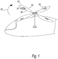
- FIG. 1 there is illustrated a helicopter 40 having one or more rotor blades 45 configured for rotation in a rotor direction 50.
- Each rotor blade 45 has one or more control flaps 55 (three shown) disposed thereon.
- control flaps 55 are disposed on a trailing edge 60 of the blade.
- the trailing edge 60 is the edge of the blade that follows or trails the movement of the rotor blade 45 as the blade is rotated in the rotor direction 50.
- control flaps 55 it is contemplated by the present disclosure for control flaps 55 to be disposed on a leading edge 65 of the rotor blade 45. Additionally, it is contemplated by the present disclosure for control flaps 55 to be disposed on any combination of the trailing and leading edges 60, 65, respectively.
- each control flap 55 is preferably controlled by a motor based actuator 70 ( FIGS. 2 and 3 ) on board each blade 45.
- control flaps 55 can be used to replace the swashplate of the prior art.
- control flaps 55 can be used to impart enhanced performance by delaying retreating blade stall.
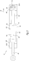
- a first embodiment of a self-lubricated actuator 70 is shown.
- Actuator 70 is placed onboard rotor blade 45 and is configured to rotate control flap 55, illustrated for purposes of example only on trailing edge 60, about a shaft 75.
- Actuator 70 includes an output rod 80 connected to control flap 55 via a first transmission part 85.
- Actuator 70 is configured to extend and retract output rod 80 from the actuator in a linear direction that is parallel of to a radial direction 90 of rotor blade 45.
- the radial direction 90 is defined as the direction that is generally parallel to the length of the rotor blade 45.
- First transmission part 85 is configured to convert the linear extension and retraction movement of output rod 80 into a positive or negative rotational movement of control flap 55 around shaft 75 so that the control flap can selectively change the pitch of rotor blade 45.
- first transmission part 85 includes a crank 165 and a link 170.
- actuator 70 has an outer housing 95 that encloses an internal cavity or oil reservoir 100.
- Outer housing 95 includes a first seal 105-1 at a first end and a second seal 105-2 at a second end to maintain the oil reservoir 100 substantially sealed.
- First seal 105-1 is a fixed seal
- second seal 105-2 is a sliding seal that allows output rod 80 to extend and retract.
- Housing 95 includes a brushless permanent magnet motor 110 having a shaft 115 that is free to rotate within bearing 120, which is positioned proximate to the seal 105 at the first end. Housing 95 also includes a second transmission device 125 operatively connected to output rod 80, where the second transmission device 125 is configured to convert a rotary movement of motor shaft 115 into the linear movement of the output rod in the direction parallel to the radial direction 90.
- second transmission device 125 is a linear roller screw having a receiving component 130 and an outer screw block 135.
- Output rod 80 is preferably made from tungsten carbide or other similarly metallic material for long performance.
- Housing 95 includes a volume of oil 140 that is sufficient to substantially fill internal cavity 100.
- the effect of centrifugal forces on oil 140 can be mitigated.
- the centrifugal force is along the radial direction 90 and is directed towards bearing 120.
- actuator 70 being substantially full of oil 140, is configured to maintain bearing 120, second transmission device 125, and motor 110 substantially immersed and, thus, lubricated by, oil 140.
- the forces on oil 140 urge the oil towards first seal 105-1 and away from second seal 105-2, which assists in preventing leakage of the oil between the second seal and output rod 80.
- rotor blade 45 during rotation in rotation direction 50 can impart a centrifugal force on the grease of at least about 200 g's and typically in excess of 500 g's, which has been determined by the present disclosure to be sufficient to force the grease of prior art actuators away from the critical contact surfaces of the actuator, thereby exposing the internal components to potential seizure.
- Actuator 70 advantageously avoids this common problem.
- housing 95 By sealing housing 95 and substantially filling the internal cavity 100 of the housing with oil 140, it has been determined by the present disclosure that all critical moving parts within housing 95 can be lubricated even during the high centrifugal force imparted on the actuator 70.
- there is a sufficient volume of oil 140 in internal cavity 100 so that, even when exposed to the centrifugal force, the oil still substantially immerses the internal components of actuator 70 (e.g., bearing 120, motor 110, second transmission device125).
- actuator 70 By maintaining the internal components of actuator 70 substantially immersed in oil 140, even during high centrifugal forces, actuator 70 is advantageously configured to ensure a substantially friction free operational environment.
- the oil 140 in actuator 70 moves from a first position when the rotor blade 45 is in a non-operational state to a second position when the rotor blade is in an operational state (i.e., application of centrifugal force).
- the internal components of actuator 70 remain substantially immersed in oil 140, even when the oil is in the second position.
- oil 140 In addition to lubricating the internal moving components of actuator 70, oil 140 also operates as a medium of heat transfer. Oil 140 substantially immerses the contact surfaces of the bearing 120 and second transmission device 125 that experience friction during operation of motor 110. Significantly, oil 140 transports heat away from motor 110 and the contact surfaces towards housing 95. Such heat transfer permits a substantial amount of power to be extracted from motor for rapid flap control. The viscous nature of oil 140 permits heat transport away from high friction sites towards the cooler parts of housing 95, still substantially immersed in the oil. Further, oil 140 transports the heat towards housing 95 to be dissipated outside of actuator 70.
- a traditional grease lubricant is not capable of acting as an effective heat transport medium.
- Grease that is localized at a site of friction only operates to lubricate that site for a limited amount of time and is not capable to dissipating generated heat to other areas within the housing or external to the housing. Further, the grease itself is not an effective medium to dissipate heat.
- second transmission device 125 is described herein above by way of example as only including a linear roller screw. Of course, it is contemplated by the present disclosure for second transmission device 125 include any components capable of converting the rotary movement of motor shaft 115 into the linear movement of the output rod 80 along the radial direction 90.
- actuator 70 includes second transmission 125 that further includes a two-stage spur gear 145.
- two stage spur gear 145 includes a first gear 150, which is driven by motor shaft 115, and a second gear 155, which is driven by the first gear 150.
- spur gear 145 includes an output shaft 160, which is driven by the second gear 155.
- Output shaft 160 is operatively connected to output rod 80 via the second transmission device 125, which is configured to convert a rotary movement of output shaft 160 into the linear movement of the output rod 80 in a direction parallel to the radial direction 90.
- actuator 70 includes a plurality of bearings 120 supporting the various gears and shafts.
- two stage spur gear system 145 can reduce the overall length (as measured along the radial direction 90 of Fig. 2 ).
- brushless permanent magnet motor 110 and output rod 80 are parallel to one another inside housing 95.
- housing 95 defines a single oil reservoir 100, which includes a volume of oil 140 that is sufficient to substantially fill internal cavity 100.
- actuator 70 being substantially full of oil 140, is configured to maintain bearings 120, second transmission device 125, gear system 145, and motor 110 substantially immersed and, thus, lubricated by, oil 140 regardless of the application of centrifugal force on the actuator. Further, oil 140 can dissipate heat through the oil in to housing 95.
- housing 95 defines a two oil reservoirs 100-1 and 100-2, which each includes a volume of oil 140 that is sufficient to substantially fill the particular internal cavity 100.
- actuator 70 being substantially full of oil 140, is configured to maintain bearings 120, second transmission device 125, gear system 145, and motor 110 substantially immersed and, thus, lubricated by, oil 140 regardless of the application of centrifugal force on the actuator. Further, oil 140 can dissipate heat through the oil in to housing 95.
- one reservoir 100-1 is defined at second transmission device 125, while the second reservoir 100-2 is defined at gear system 145. In this manner, less oil 140 is required so that the weight of actuator 70 can be minimized. Further, this embodiment allows the use of separate oils 140 for the different component of the actuator.
- actuator 70 is configured mounted on board rotor blade 45 in the radial direction 90 so that output rod 80 moves in a direction parallel to the radial direction to rotate control flap 55 about shaft 75.
- the actuator 70 it is contemplated by the present disclosure for the actuator 70 to be mounted onboard rotor blade 45 in any desired manner.
- actuator 70 is illustrated in Fig. 6 , mounted onboard rotor blade 45 in a chordwise direction, namely perpendicular to radial direction 90.
- the chordwise direction is defined as the direction generally between the leading edge 65 and the trailing edge 60 of the rotor blade 45.
- actuator 70 is configured to extend and retract output rod 80 from the actuator in the chordwise direction.
- first transmission part 85 is configured to convert the linear extension and retraction movement of output rod 80 into a positive or negative rotational movement of control flap 55 around shaft 75 so that the control flap can selectively change the pitch of rotor blade 45.
- actuator 70 has a sufficient volume of oil 140 in the one or more internal cavities 100 so that, even when exposed to the centrifugal force, the oil still substantially immerses the internal components of actuator 70 (e.g., bearing 120, motor 110, second transmission device 125, and, when present, spur gear 145).
- actuator 70 is advantageously configured to ensure a substantially friction free operational environment.
Landscapes
- Engineering & Computer Science (AREA)
- Mechanical Engineering (AREA)
- Aviation & Aerospace Engineering (AREA)
- General Details Of Gearings (AREA)
- Transmission Devices (AREA)
Claims (11)
- Selbstschmierender Aktuator (70) für eine Steuerklappe (55) eines Hubschrauberrotorblattes (45), umfassend:ein Gehäuse (95), das einen inneren Hohlraum (100) definiert;einen Motor (110), der in dem inneren Hohlraum (100) zum Drehen einer Motorwelle (115) in dem inneren Hohlraum (100) angeordnet ist; undeine Ausgangsstange (80), die sich von dem inneren Hohlraum (100) erstreckt, wobei sich die Ausgangsstange (80) von dem Gehäuse (95) erstreckt;dadurch gekennzeichnet, dass er ferner Folgendes umfasst:eine Übertragungsvorrichtung (125), die der Motorwelle (115) funktionsfähig zugeordnet ist, um die Drehung der Motorwelle (115) in eine lineare Bewegung der Ausgangsstange (80) umzuwandeln, um die Ausgangsstange (80) in Bezug auf das Aktuatorgehäuse (95) aus- und einzufahren, wobei sich die Ausgangsstange (80) zumindest teilweise innerhalb des inneren Hohlraums (100) erstreckt, wobei der innere Hohlraum (100) ein Volumen an Schmiermittel enthält, das ausreicht, um die Motorwelle (115), die Übertragungsvorrichtung (125) und die Ausgangsstange (80), die sich zumindest teilweise innerhalb des inneren Hohlraums (100) befindet, im Wesentlichen einzutauchen.
- Aktuator (70) nach Anspruch 1, wobei der Motor (110), die Motorwelle (115) und die Übertragungsvorrichtung (125) als Reaktion auf die Einwirkung einer Zentrifugalkraft auf den Aktuator (70) im Wesentlichen in das Schmiermedium eingetaucht sind.
- Aktuator (70) nach Anspruch 2, ferner umfassend eine erste Dichtung (105-1), die an dem Gehäuse (95) angrenzend an den inneren Hohlraum (100) montiert ist, wobei die Zentrifugalkraft gerichtet ist, um das Schmiermedium in Richtung der ersten Dichtung (105-1) zu drücken.
- Aktuator (70) nach Anspruch 2, ferner umfassend eine erste Dichtung (105-1) und eine zweite Dichtung (105-2), die an dem Gehäuse (95) angrenzend an den inneren Hohlraum (100) montiert sind, wobei die Zentrifugalkraft gerichtet ist, um das Schmiermedium in Richtung der ersten Dichtung (105-1) und weg von der zweiten Dichtung (105-2) zu zwingen.
- Aktuator (70) nach Anspruch 4, wobei die zweite Dichtung (105-2) angrenzend an die Ausgangsstange (80) angeordnet ist.
- Aktuator (70) nach Anspruch 5, wobei die zweite Dichtung (105-2) den Abschnitt der Ausgangsstange (80), der sich zumindest teilweise innerhalb des inneren Hohlraums (100) befindet, von dem Abschnitt der Ausgangsstange (80) trennt, der sich von dem inneren Hohlraum (100) erstreckt, so dass nur der Abschnitt der Ausgangsstange (80), der sich zumindest teilweise innerhalb des inneren Hohlraums (100) befindet, dem Volumen des Schmiermediums ausgesetzt ist und der Abschnitt der Ausgangsstange (80), der sich von dem inneren Hohlraum (100) erstreckt, nicht dem Volumen des Schmiermediums ausgesetzt ist.
- Aktuator (70) nach Anspruch 1, wobei nur der Abschnitt der Ausgangsstange (80), der sich zumindest teilweise in dem inneren Hohlraum (100) befindet, dem Volumen des Schmiermediums ausgesetzt ist.
- Aktuator (70) nach Anspruch 7, wobei der Abschnitt der Ausgangsstange (80), der sich von dem inneren Hohlraum (100) erstreckt, nicht dem Volumen des Schmiermediums ausgesetzt ist.
- Aktuator (70) nach Anspruch 1, wobei die Übertragungsvorrichtung (125) einen linearen Kugelgewindetrieb umfasst.
- Aktuator (70) nach Anspruch 1, wobei das Schmiermedium ausreicht, um Wärme von der Übertragungsvorrichtung (125) zu dem Gehäuse (95) abzuleiten.
- Aktuator (70) nach Anspruch 1, ferner umfassend ein oder mehrere Lager (120) in dem inneren Hohlraum (100), wobei das Volumen des Schmiermediums ausreichend ist, um das eine oder die mehreren Lager (120) während der Einwirkung der Zentrifugalkraft im Wesentlichen einzutauchen.
Applications Claiming Priority (2)
| Application Number | Priority Date | Filing Date | Title |
|---|---|---|---|
| US11/567,773 US7677868B2 (en) | 2006-12-07 | 2006-12-07 | Self-lubricated actuator for on-blade rotor control |
| PCT/US2007/084396 WO2008147450A1 (en) | 2006-12-07 | 2007-11-12 | Self-lubricated actuator for on-blade rotor control |
Publications (3)
| Publication Number | Publication Date |
|---|---|
| EP2094562A1 EP2094562A1 (de) | 2009-09-02 |
| EP2094562A4 EP2094562A4 (de) | 2017-05-17 |
| EP2094562B1 true EP2094562B1 (de) | 2019-01-23 |
Family
ID=39498249
Family Applications (1)
| Application Number | Title | Priority Date | Filing Date |
|---|---|---|---|
| EP07875042.9A Not-in-force EP2094562B1 (de) | 2006-12-07 | 2007-11-12 | Selbstschmierender aktuator für rotorsteuerung auf der laufschaufel |
Country Status (3)
| Country | Link |
|---|---|
| US (1) | US7677868B2 (de) |
| EP (1) | EP2094562B1 (de) |
| WO (1) | WO2008147450A1 (de) |
Families Citing this family (16)
| Publication number | Priority date | Publication date | Assignee | Title |
|---|---|---|---|---|
| US8727722B2 (en) * | 2007-12-27 | 2014-05-20 | General Electric Company | System and methods for adaptive blade control surface adjustment |
| EP2341259B1 (de) * | 2010-01-05 | 2019-03-13 | Sikorsky Aircraft Corporation | Mechanisches System für Hochbeschleunigungs-Umgebungen |
| GB201009087D0 (en) | 2010-05-28 | 2010-07-14 | Microtecnica Actuation Technol | Actuator assembly for use in a rotor blade |
| GB201009086D0 (en) * | 2010-05-28 | 2010-07-14 | Microtecnica Actuation Technol | Actuator for use in a rotor blade |
| US8823229B2 (en) * | 2010-06-04 | 2014-09-02 | Aries Engineering Company, Inc. | Electro-mechanical actuator |
| EP2450764B1 (de) | 2010-11-05 | 2016-05-11 | Sikorsky Aircraft Corporation | Implementierung einer linearen Kalman-Filter-Statusschätzfunktion zum Aktorausgleich |
| US9090343B2 (en) | 2011-10-13 | 2015-07-28 | Sikorsky Aircraft Corporation | Rotor blade component cooling |
| US9407121B2 (en) * | 2012-05-31 | 2016-08-02 | Hamilton Sundstrand Corporation | Electromechanical rotary actuator and method |
| EP2674360A1 (de) | 2012-06-13 | 2013-12-18 | Claverham Limited | Trocken geschmierter linearer Aktuator für Rotorsteuerung im Rotorblatt |
| EP2703288B1 (de) * | 2012-08-31 | 2018-03-14 | Claverham Limited | Elektromechanischer linearer Aktuator für Rotorsteuerung im Blatt |
| US9464532B2 (en) * | 2013-03-05 | 2016-10-11 | Bell Helicopter Textron Inc. | System and method for reducing rotor blade noise |
| US9677663B2 (en) | 2013-06-28 | 2017-06-13 | Sikorsky Aircraft Corporation | Gear geometry with fluid reservoir and fluid paths |
| FR3011818B1 (fr) | 2013-10-11 | 2015-12-25 | Eurocopter France | Pale a vrillage adaptatif, et aeronef muni d'une telle pale |
| US10571074B2 (en) * | 2014-10-28 | 2020-02-25 | Sikorsky Aricraft Corporation | Lubricant level sensing for an actuator |
| CA3012596C (en) * | 2016-03-10 | 2020-04-28 | Halliburton Energy Services, Inc. | Device including a seal assembly |
| CN108275259B (zh) * | 2017-12-22 | 2021-04-20 | 兰州空间技术物理研究所 | 一种扁平副翼舵机机构 |
Family Cites Families (12)
| Publication number | Priority date | Publication date | Assignee | Title |
|---|---|---|---|---|
| US4500805A (en) * | 1984-02-07 | 1985-02-19 | Esco Design, Inc. | Electromechanical linear actuator |
| US4858481A (en) | 1985-05-13 | 1989-08-22 | Brunswick Valve & Control, Inc. | Position controlled linear actuator |
| NL8801948A (nl) | 1988-08-04 | 1990-03-01 | Haan Mechatronics | Lineaire actuator. |
| US5041748A (en) | 1989-10-16 | 1991-08-20 | Sundstrand Corporation | Lightweight, direct drive electromechanical actuator |
| JP2624090B2 (ja) * | 1992-07-27 | 1997-06-25 | ヤマハ株式会社 | 自動演奏装置 |
| US5387083A (en) * | 1992-12-23 | 1995-02-07 | Alliedsignal Inc. | Helicopter servoflap actuator having mechanical stop and oil pump |
| JP2617281B2 (ja) | 1995-03-27 | 1997-06-04 | 株式会社コミュータヘリコプタ先進技術研究所 | フラップ付きヘリコプタロータ |
| GB2299562A (en) * | 1995-04-01 | 1996-10-09 | Nigel Howard Mckrill | Actuator for helicopter rotor blade aileron |
| JPH09133199A (ja) * | 1995-11-09 | 1997-05-20 | Mitsubishi Heavy Ind Ltd | 自給油型歯車 |
| JP2907335B1 (ja) | 1998-03-24 | 1999-06-21 | 株式会社コミュータヘリコプタ先進技術研究所 | ロータブレードのフラップ駆動装置 |
| JP2002136025A (ja) * | 2000-10-26 | 2002-05-10 | Mitsubishi Electric Corp | 電磁機器 |
| US6688767B2 (en) * | 2001-12-11 | 2004-02-10 | The Boeing Company | Self-aligning dynamic hinge sleeve |
-
2006
- 2006-12-07 US US11/567,773 patent/US7677868B2/en active Active
-
2007
- 2007-11-12 EP EP07875042.9A patent/EP2094562B1/de not_active Not-in-force
- 2007-11-12 WO PCT/US2007/084396 patent/WO2008147450A1/en not_active Ceased
Non-Patent Citations (1)
| Title |
|---|
| None * |
Also Published As
| Publication number | Publication date |
|---|---|
| US7677868B2 (en) | 2010-03-16 |
| US20080138203A1 (en) | 2008-06-12 |
| EP2094562A4 (de) | 2017-05-17 |
| WO2008147450A1 (en) | 2008-12-04 |
| EP2094562A1 (de) | 2009-09-02 |
Similar Documents
| Publication | Publication Date | Title |
|---|---|---|
| EP2094562B1 (de) | Selbstschmierender aktuator für rotorsteuerung auf der laufschaufel | |
| US5387083A (en) | Helicopter servoflap actuator having mechanical stop and oil pump | |
| EP2169204B1 (de) | Stellantrieb | |
| RU2549735C2 (ru) | Узел лопасти несущего винта, воздушное судно с несущим винтом и приводная система закрылка лопасти несущего винта | |
| EP2189672A2 (de) | Lagervorrichtung und Windturbine mit der Lagervorrichtung | |
| US9440738B2 (en) | Dry lubricated rotary actuator for in blade rotor control | |
| EP2982604A1 (de) | Drehmomentausgleichsrotor eines Hubschraubers | |
| CA2913778C (en) | Turbine with hydraulic variable pitch system | |
| GB2522113A (en) | Wind turbine | |
| US20200109777A1 (en) | Aircraft gearbox lubrication system with multiple lubrication subsystems | |
| EP3480116A1 (de) | Elektromechanische aktuatorsysteme zum öffnen und schliessen von flugzeugtriebwerksverkleidungstüren | |
| US20190101208A1 (en) | Ballscrew actuators | |
| CN101627249A (zh) | 自动润滑销组件 | |
| US9517839B2 (en) | Electromechanical linear actuator for in blade rotor control | |
| EP3486501B1 (de) | Aktuatoranordnung mit selbstschmierenden komponenten | |
| EP3081485B1 (de) | Aktuator zur verwendung in einem rotorblatt | |
| EP2341259B1 (de) | Mechanisches System für Hochbeschleunigungs-Umgebungen | |
| US10571074B2 (en) | Lubricant level sensing for an actuator | |
| DE102018109027B4 (de) | Verstelleinrichtung für einen Nockenwellenversteller | |
| EP2990650A1 (de) | Pumpe auf welle | |
| TR2022020007A1 (tr) | Bir güç aktarım sistemi. |
Legal Events
| Date | Code | Title | Description |
|---|---|---|---|
| PUAI | Public reference made under article 153(3) epc to a published international application that has entered the european phase |
Free format text: ORIGINAL CODE: 0009012 |
|
| 17P | Request for examination filed |
Effective date: 20090706 |
|
| AK | Designated contracting states |
Kind code of ref document: A1 Designated state(s): AT BE BG CH CY CZ DE DK EE ES FI FR GB GR HU IE IS IT LI LT LU LV MC MT NL PL PT RO SE SI SK TR |
|
| DAX | Request for extension of the european patent (deleted) | ||
| RA4 | Supplementary search report drawn up and despatched (corrected) |
Effective date: 20170421 |
|
| RIC1 | Information provided on ipc code assigned before grant |
Ipc: B64C 27/72 20060101ALI20170413BHEP Ipc: B64C 27/615 20060101ALI20170413BHEP Ipc: B64C 9/00 20060101AFI20170413BHEP |
|
| RIC1 | Information provided on ipc code assigned before grant |
Ipc: B64C 9/00 20060101AFI20180604BHEP Ipc: B64C 27/72 20060101ALI20180604BHEP Ipc: B64C 27/615 20060101ALI20180604BHEP |
|
| GRAP | Despatch of communication of intention to grant a patent |
Free format text: ORIGINAL CODE: EPIDOSNIGR1 |
|
| STAA | Information on the status of an ep patent application or granted ep patent |
Free format text: STATUS: GRANT OF PATENT IS INTENDED |
|
| INTG | Intention to grant announced |
Effective date: 20180802 |
|
| GRAS | Grant fee paid |
Free format text: ORIGINAL CODE: EPIDOSNIGR3 |
|
| GRAA | (expected) grant |
Free format text: ORIGINAL CODE: 0009210 |
|
| STAA | Information on the status of an ep patent application or granted ep patent |
Free format text: STATUS: THE PATENT HAS BEEN GRANTED |
|
| AK | Designated contracting states |
Kind code of ref document: B1 Designated state(s): AT BE BG CH CY CZ DE DK EE ES FI FR GB GR HU IE IS IT LI LT LU LV MC MT NL PL PT RO SE SI SK TR |
|
| REG | Reference to a national code |
Ref country code: GB Ref legal event code: FG4D |
|
| REG | Reference to a national code |
Ref country code: CH Ref legal event code: EP |
|
| REG | Reference to a national code |
Ref country code: AT Ref legal event code: REF Ref document number: 1091245 Country of ref document: AT Kind code of ref document: T Effective date: 20190215 |
|
| REG | Reference to a national code |
Ref country code: IE Ref legal event code: FG4D |
|
| REG | Reference to a national code |
Ref country code: DE Ref legal event code: R096 Ref document number: 602007057523 Country of ref document: DE |
|
| REG | Reference to a national code |
Ref country code: NL Ref legal event code: MP Effective date: 20190123 |
|
| PG25 | Lapsed in a contracting state [announced via postgrant information from national office to epo] |
Ref country code: NL Free format text: LAPSE BECAUSE OF FAILURE TO SUBMIT A TRANSLATION OF THE DESCRIPTION OR TO PAY THE FEE WITHIN THE PRESCRIBED TIME-LIMIT Effective date: 20190123 |
|
| PG25 | Lapsed in a contracting state [announced via postgrant information from national office to epo] |
Ref country code: PL Free format text: LAPSE BECAUSE OF FAILURE TO SUBMIT A TRANSLATION OF THE DESCRIPTION OR TO PAY THE FEE WITHIN THE PRESCRIBED TIME-LIMIT Effective date: 20190123 Ref country code: SE Free format text: LAPSE BECAUSE OF FAILURE TO SUBMIT A TRANSLATION OF THE DESCRIPTION OR TO PAY THE FEE WITHIN THE PRESCRIBED TIME-LIMIT Effective date: 20190123 Ref country code: FI Free format text: LAPSE BECAUSE OF FAILURE TO SUBMIT A TRANSLATION OF THE DESCRIPTION OR TO PAY THE FEE WITHIN THE PRESCRIBED TIME-LIMIT Effective date: 20190123 Ref country code: PT Free format text: LAPSE BECAUSE OF FAILURE TO SUBMIT A TRANSLATION OF THE DESCRIPTION OR TO PAY THE FEE WITHIN THE PRESCRIBED TIME-LIMIT Effective date: 20190523 Ref country code: LT Free format text: LAPSE BECAUSE OF FAILURE TO SUBMIT A TRANSLATION OF THE DESCRIPTION OR TO PAY THE FEE WITHIN THE PRESCRIBED TIME-LIMIT Effective date: 20190123 Ref country code: ES Free format text: LAPSE BECAUSE OF FAILURE TO SUBMIT A TRANSLATION OF THE DESCRIPTION OR TO PAY THE FEE WITHIN THE PRESCRIBED TIME-LIMIT Effective date: 20190123 |
|
| REG | Reference to a national code |
Ref country code: AT Ref legal event code: MK05 Ref document number: 1091245 Country of ref document: AT Kind code of ref document: T Effective date: 20190123 |
|
| PG25 | Lapsed in a contracting state [announced via postgrant information from national office to epo] |
Ref country code: LV Free format text: LAPSE BECAUSE OF FAILURE TO SUBMIT A TRANSLATION OF THE DESCRIPTION OR TO PAY THE FEE WITHIN THE PRESCRIBED TIME-LIMIT Effective date: 20190123 Ref country code: BG Free format text: LAPSE BECAUSE OF FAILURE TO SUBMIT A TRANSLATION OF THE DESCRIPTION OR TO PAY THE FEE WITHIN THE PRESCRIBED TIME-LIMIT Effective date: 20190423 Ref country code: IS Free format text: LAPSE BECAUSE OF FAILURE TO SUBMIT A TRANSLATION OF THE DESCRIPTION OR TO PAY THE FEE WITHIN THE PRESCRIBED TIME-LIMIT Effective date: 20190523 Ref country code: GR Free format text: LAPSE BECAUSE OF FAILURE TO SUBMIT A TRANSLATION OF THE DESCRIPTION OR TO PAY THE FEE WITHIN THE PRESCRIBED TIME-LIMIT Effective date: 20190424 |
|
| REG | Reference to a national code |
Ref country code: DE Ref legal event code: R097 Ref document number: 602007057523 Country of ref document: DE |
|
| PG25 | Lapsed in a contracting state [announced via postgrant information from national office to epo] |
Ref country code: DK Free format text: LAPSE BECAUSE OF FAILURE TO SUBMIT A TRANSLATION OF THE DESCRIPTION OR TO PAY THE FEE WITHIN THE PRESCRIBED TIME-LIMIT Effective date: 20190123 Ref country code: EE Free format text: LAPSE BECAUSE OF FAILURE TO SUBMIT A TRANSLATION OF THE DESCRIPTION OR TO PAY THE FEE WITHIN THE PRESCRIBED TIME-LIMIT Effective date: 20190123 Ref country code: RO Free format text: LAPSE BECAUSE OF FAILURE TO SUBMIT A TRANSLATION OF THE DESCRIPTION OR TO PAY THE FEE WITHIN THE PRESCRIBED TIME-LIMIT Effective date: 20190123 Ref country code: SK Free format text: LAPSE BECAUSE OF FAILURE TO SUBMIT A TRANSLATION OF THE DESCRIPTION OR TO PAY THE FEE WITHIN THE PRESCRIBED TIME-LIMIT Effective date: 20190123 Ref country code: CZ Free format text: LAPSE BECAUSE OF FAILURE TO SUBMIT A TRANSLATION OF THE DESCRIPTION OR TO PAY THE FEE WITHIN THE PRESCRIBED TIME-LIMIT Effective date: 20190123 |
|
| PLBE | No opposition filed within time limit |
Free format text: ORIGINAL CODE: 0009261 |
|
| STAA | Information on the status of an ep patent application or granted ep patent |
Free format text: STATUS: NO OPPOSITION FILED WITHIN TIME LIMIT |
|
| PG25 | Lapsed in a contracting state [announced via postgrant information from national office to epo] |
Ref country code: AT Free format text: LAPSE BECAUSE OF FAILURE TO SUBMIT A TRANSLATION OF THE DESCRIPTION OR TO PAY THE FEE WITHIN THE PRESCRIBED TIME-LIMIT Effective date: 20190123 |
|
| 26N | No opposition filed |
Effective date: 20191024 |
|
| PG25 | Lapsed in a contracting state [announced via postgrant information from national office to epo] |
Ref country code: SI Free format text: LAPSE BECAUSE OF FAILURE TO SUBMIT A TRANSLATION OF THE DESCRIPTION OR TO PAY THE FEE WITHIN THE PRESCRIBED TIME-LIMIT Effective date: 20190123 |
|
| PG25 | Lapsed in a contracting state [announced via postgrant information from national office to epo] |
Ref country code: TR Free format text: LAPSE BECAUSE OF FAILURE TO SUBMIT A TRANSLATION OF THE DESCRIPTION OR TO PAY THE FEE WITHIN THE PRESCRIBED TIME-LIMIT Effective date: 20190123 |
|
| REG | Reference to a national code |
Ref country code: CH Ref legal event code: PL |
|
| PG25 | Lapsed in a contracting state [announced via postgrant information from national office to epo] |
Ref country code: LU Free format text: LAPSE BECAUSE OF NON-PAYMENT OF DUE FEES Effective date: 20191112 Ref country code: CH Free format text: LAPSE BECAUSE OF NON-PAYMENT OF DUE FEES Effective date: 20191130 Ref country code: MC Free format text: LAPSE BECAUSE OF FAILURE TO SUBMIT A TRANSLATION OF THE DESCRIPTION OR TO PAY THE FEE WITHIN THE PRESCRIBED TIME-LIMIT Effective date: 20190123 Ref country code: LI Free format text: LAPSE BECAUSE OF NON-PAYMENT OF DUE FEES Effective date: 20191130 |
|
| REG | Reference to a national code |
Ref country code: BE Ref legal event code: MM Effective date: 20191130 |
|
| PG25 | Lapsed in a contracting state [announced via postgrant information from national office to epo] |
Ref country code: IE Free format text: LAPSE BECAUSE OF NON-PAYMENT OF DUE FEES Effective date: 20191112 |
|
| PG25 | Lapsed in a contracting state [announced via postgrant information from national office to epo] |
Ref country code: BE Free format text: LAPSE BECAUSE OF NON-PAYMENT OF DUE FEES Effective date: 20191130 |
|
| PG25 | Lapsed in a contracting state [announced via postgrant information from national office to epo] |
Ref country code: CY Free format text: LAPSE BECAUSE OF FAILURE TO SUBMIT A TRANSLATION OF THE DESCRIPTION OR TO PAY THE FEE WITHIN THE PRESCRIBED TIME-LIMIT Effective date: 20190123 |
|
| PG25 | Lapsed in a contracting state [announced via postgrant information from national office to epo] |
Ref country code: HU Free format text: LAPSE BECAUSE OF FAILURE TO SUBMIT A TRANSLATION OF THE DESCRIPTION OR TO PAY THE FEE WITHIN THE PRESCRIBED TIME-LIMIT; INVALID AB INITIO Effective date: 20071112 Ref country code: MT Free format text: LAPSE BECAUSE OF FAILURE TO SUBMIT A TRANSLATION OF THE DESCRIPTION OR TO PAY THE FEE WITHIN THE PRESCRIBED TIME-LIMIT Effective date: 20190123 |
|
| PGFP | Annual fee paid to national office [announced via postgrant information from national office to epo] |
Ref country code: DE Payment date: 20211126 Year of fee payment: 15 Ref country code: FR Payment date: 20211124 Year of fee payment: 15 Ref country code: GB Payment date: 20211129 Year of fee payment: 15 |
|
| PGFP | Annual fee paid to national office [announced via postgrant information from national office to epo] |
Ref country code: IT Payment date: 20211122 Year of fee payment: 15 |
|
| REG | Reference to a national code |
Ref country code: DE Ref legal event code: R119 Ref document number: 602007057523 Country of ref document: DE |
|
| P01 | Opt-out of the competence of the unified patent court (upc) registered |
Effective date: 20230520 |
|
| GBPC | Gb: european patent ceased through non-payment of renewal fee |
Effective date: 20221112 |
|
| PG25 | Lapsed in a contracting state [announced via postgrant information from national office to epo] |
Ref country code: IT Free format text: LAPSE BECAUSE OF NON-PAYMENT OF DUE FEES Effective date: 20221112 Ref country code: GB Free format text: LAPSE BECAUSE OF NON-PAYMENT OF DUE FEES Effective date: 20221112 Ref country code: DE Free format text: LAPSE BECAUSE OF NON-PAYMENT OF DUE FEES Effective date: 20230601 |
|
| PG25 | Lapsed in a contracting state [announced via postgrant information from national office to epo] |
Ref country code: FR Free format text: LAPSE BECAUSE OF NON-PAYMENT OF DUE FEES Effective date: 20221130 |