EP2189726B1 - Poignée escamotable pour une porte d'un appareil ménager et porte d'un appareil ménager doté d'une telle poignée - Google Patents
Poignée escamotable pour une porte d'un appareil ménager et porte d'un appareil ménager doté d'une telle poignée Download PDFInfo
- Publication number
- EP2189726B1 EP2189726B1 EP09175731.0A EP09175731A EP2189726B1 EP 2189726 B1 EP2189726 B1 EP 2189726B1 EP 09175731 A EP09175731 A EP 09175731A EP 2189726 B1 EP2189726 B1 EP 2189726B1
- Authority
- EP
- European Patent Office
- Prior art keywords
- rod
- handle
- holder
- sliding block
- rod holder
- Prior art date
- Legal status (The legal status is an assumption and is not a legal conclusion. Google has not performed a legal analysis and makes no representation as to the accuracy of the status listed.)
- Active
Links
Images


Classifications
-
- F—MECHANICAL ENGINEERING; LIGHTING; HEATING; WEAPONS; BLASTING
- F24—HEATING; RANGES; VENTILATING
- F24C—DOMESTIC STOVES OR RANGES ; DETAILS OF DOMESTIC STOVES OR RANGES, OF GENERAL APPLICATION
- F24C15/00—Details
- F24C15/02—Doors specially adapted for stoves or ranges
- F24C15/024—Handles
-
- E—FIXED CONSTRUCTIONS
- E05—LOCKS; KEYS; WINDOW OR DOOR FITTINGS; SAFES
- E05B—LOCKS; ACCESSORIES THEREFOR; HANDCUFFS
- E05B1/00—Knobs or handles for wings; Knobs, handles, or press buttons for locks or latches on wings
- E05B1/0015—Knobs or handles which do not operate the bolt or lock, e.g. non-movable; Mounting thereof
-
- E—FIXED CONSTRUCTIONS
- E05—LOCKS; KEYS; WINDOW OR DOOR FITTINGS; SAFES
- E05B—LOCKS; ACCESSORIES THEREFOR; HANDCUFFS
- E05B5/00—Handles completely let into the surface of the wing
Definitions
- the invention relates to a retractable handle device with a handle bar and with bar holders, which are connected to the handle bar and a handle holder. Furthermore, the invention relates to a door for a household appliance with such a handle device.
- a closure device for the door of a hot air steam oven known.
- a handle device for the door has a handle bar and thus fixed and immovably connected holder for this handle bar, wherein the handle device can be pushed in a linear movement in the door or pulled out of this. In the retracted state, the handle device is recessed substantially in the door. Also for this embodiment, a relatively large amount of space is required. In addition, the accessibility is limited, so that the removal of the recessed handle can be done only very expensive and laborious.
- DE 14 57 243 A1 a retractable carrying handle.
- the DE 907 116 C discloses a fuse on travel suitcases.
- the DE 823 487 C discloses a suitcase with a security device against stealing.
- the US 3,572,870 discloses a fold-out and retractable handle device with locking means therefor.
- a retractable handle device comprises a handle bar and rod holder for holding this handle bar.
- the pole holders are connected to the handle bar and a handle holder.
- the rod holders are relatively movable to the handlebar and arranged relatively movable to handle holder and on a rod holder at least one sliding block is arranged, which engages for guiding the movement of a rod holder in a guide track of a handle holder.
- a rod holder has on its upper side at least two spaced-apart upper sliding blocks. Through the plurality of sliding blocks, the leadership of the rod holder can be improved and unstable brackets and an unstable guide can be avoided. As a result, the wear can be reduced.
- a first upper sliding block is disposed at a front end of the rod holder and a second upper sliding block is positioned in the longitudinal direction of the rod holder approximately centered on the rod holder at the top thereof. Due to the relatively large spacing of the sliding blocks, the occurring position forces can be kept as small as possible.
- the handle holder has a slot-like receiving space into which the rod holders extend.
- components of the gripping device can thereby be arranged wear-resistant and protected against damage or other interferences, and moreover, the space requirement of the gripping device can be further reduced.
- two separate upper guideways are formed on an upper cover of the receiving space, and an upper sliding block in each case engages in one of the upper guideways. Due to this at least duality of two guideways and two sliding blocks, the guide curve or the guideway can be optimized. This can be done in terms of space-saving as possible depression and extension of the handle bar and on the other hand with regard to minimal displacement in a direction parallel to the axis of the handle device. The entire movement during sinking or retracting can thus be done in the smallest possible space.
- a rod holder has at least two spaced-apart lower sliding blocks on a lower side. It is particularly preferred that at least one sliding block, preferably in each case two sliding blocks, are arranged both on the upper side and on the lower side. The advantages mentioned above are thereby further favored.
- two separate lower guideways are formed on a lower cover of the receiving space and in each case a lower sliding block engages in one of the lower guideways.
- Viewed in the vertical direction of the rod holder is thus performed with several sliding blocks both upwards and downwards in guideways, so that the retracting or outward movement particularly advantageous in terms of low wear and safe and reliable leadership without splaying and jamming and without tilting up or down or sideways.
- a first lower sliding block is arranged at a front end of the rod holder on the underside thereof and a second lower sliding block in the longitudinal direction of the rod holder is arranged approximately centrally on the underside of the rod holder.
- the upper and the lower sliding blocks are arranged at correspondingly symmetrical positions on the top and bottom.
- the guideways in the upper cover of the receiving space are arranged symmetrically over the guideways in the lower cover of the receiving space and thus the guideways are preferably arranged congruently when viewed from above or from below in the vertical direction.
- a guideway, in particular all guideways are formed curved at least partially.
- all guideways are curved over their entire length and preferably have the same direction of curvature.
- the guideways do not touch each other and are thus formed contactlessly and separately from one another over the entire length.
- a rod holder has an axis of rotation which is oriented perpendicular to the sinking direction and is fixedly arranged on the handle holder.
- the stationary axis of rotation is additionally arranged. To these, the rod holder can then rotate in its sinking movement or during its outward movement.
- a rod holder has an axis of rotation, which is oriented perpendicular to the sinking direction and is fixedly arranged on the handlebar.
- the rod holder has fixed axes of rotation around which it can rotate and which are fixedly arranged on different components. On the one hand, this increases the stability and stabilizes the desired movement and improves the guiding movement of the sliding blocks in the guideways.
- the rod holders are connected to a coupling mechanism for the movement synchronization of the two rod holders.
- a coupling mechanism on two push rods, which are each connected to a rod holder and coupled via a gear device which is associated with the coupling mechanism.
- the synchronization is preferably via a gear of the gear device, which can serve for damping during extension of the handle bar at the same time.
- the gear is connected to a damping device, in particular a rotary damper.
- the retractable handle device has a locking device for locking the retracted position of the handle bar, wherein the locking device comprises a sliding block which engages in a slide track, in particular a closed heart cam shape having cam track, the locking device.
- the locking device comprises a sliding block which engages in a slide track, in particular a closed heart cam shape having cam track, the locking device.
- each rod holder a spring element, in particular a leg spring, is arranged, by means of which the handle bar can be pressed into the operating position.
- the sliding block of the locking device is arranged centrally in the region of the gear device on the handlebar.
- the slide track of the locking device is preferably arranged in the lower cover of the handle holder and preferably positioned next to the gear device with the gear and preferably the rotary damper.
- the position of the rod holder can be reliably held and guided and the handle bar and thus the rod holder learn undesirably no right-left shifts.
- the guideways are shaped to allow linear movement of the handle bar, in particular not crossing each other.
- a relatively wide handle bar may be formed, which nevertheless requires a very small footprint for their movement to move out and sinking.
- only a coupling mechanism is required for motion synchronization, which is favored in particular by the sliding blocks and the guideways.
- the handle device in particular the handle bar, retractable about an axis parallel to the handle bracket.
- it can also be a movement to that effect, which not only allows sinking and retracting in the linear direction of movement, but also ensures a rotation about said axis in a rotary motion.
- the possibilities of movement can thereby be further increased considerably, which is advantageous in particular in the case of gripping devices which are mounted relative to the door to which they are attached. Especially when unfolding a door down can thus be ensured that the handle bar is always facing the user or observer and he can grab them at any time front.
- a door according to the invention for a household appliance comprises a gripping device according to the invention or an advantageous embodiment thereof.
- the gripping device in particular the handle bar, is pivotable about an axis parallel to the handle holder.
- this axis is also parallel to the plane of a front panel of the door to which the handle device is attached.
- a pivoting device which may be, for example, a cable pulling device.
- the door for a household appliance for preparing food such as an oven, a steam cooker, a microwave oven or may be provided.
- the retractable handle device is suitable for any domestic appliance which has a door.
- Fig. 3a to 3c Plan view of the handle device according to Fig. 2 in three different operating positions.
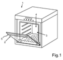
- Fig. 1 is shown in a schematic representation of a domestic appliance, which is designed as a baking oven 1.
- the oven 1 comprises a cooking chamber 3 with a front loading opening 4, which can be closed by a door 2.
- the door 2 is pivotable in its lower side via a horizontal and parallel to the oven base extending axis of rotation.
- a handle device 5 which is designed as a retractable handle device, is arranged on the outside.
- the gripping device 5 can be pivoted about an axis parallel to the pivot axis of the door 2.
- a handle bar of the handle device 5 accordingly be pivoted.
- Fig. 2 is a perspective view of the handle device 5 is shown. In this case, an operating position is shown in which a handle bar 6 is shown in the fully extended state.
- the retractable handle device 5 includes, in addition to the handle bar 6, a handle holder 7 disposed on the front side of the front plate-like part of the door 2.
- the handle holder 7 may also be arranged integrally in this front panel of the door 2 or even be part of this front panel.
- the grip device 5 further comprises two rod holders 8 and 9, which are arranged relatively movable to the handle bar 6 and relatively movable to the handle holder 7.
- the rod holders 8 and 9 are designed as levers to ensure the sinking movement of the handle bar 6 and / or the extension movement of this handle bar 6.
- the handle holder 7 has a receiving space 10, in which the bar holders 8 and 9 hineinerkyn. As in Fig. 2 can be seen by the partially transparent representation of the handle holder 7, the receiving space 10 is bounded at the top by an upper cover 11 and down through a lower cover 12.
- the covers 11 and 12 are formed as a kind of plate-like strips.
- the rod holders 8 and 9 extend into the receiving space 10.
- the rod holder 11 is connected to a first axis of rotation 13, which is arranged fixedly on the handle holder 7.
- the handle bar 6 can perform their movement linearly in the y-direction and sunk or driven out.
- the rod holders 8 and 9 have in the receiving space 10 facing elevations 13 and 15.
- the handle bar 6 or the entire handle device 5 also perform a pivotal movement about the x-axis.
- the rod holder 8 comprises an axis of rotation 14 about which it can perform a rotational movement.
- the axis of rotation 14 is fixedly positioned on the handle bar 6.
- the second rod holder 9 has a rotation axis 16.
- Kulisssensteine 18 and 19 are arranged on a top 17 of the first rod holder 8 .
- the sliding blocks 18 and 19 are arranged in that part of the rod holder 8 on the upper side 17, which extends in the receiving space 10.
- two sliding blocks are arranged on an underside of the rod holder 8, which is the top 17 opposite.
- the sliding blocks arranged on the underside of the rod holder 8 are arranged at the positions at which the sliding blocks 18 and 19 are positioned on the upper side 17.
- two guide tracks 20 and 21 are arranged. Both guideways 20 and 21 are curved over their entire length and overlap in the x-direction at least partially. The guideways 20 and 21 do not touch and also do not intersect.
- the first sliding block 18 on the upper side 17 engages in the first guide track 20, wherein the second sliding block 19 engages on the upper side 17 in the second guide track 21.
- two slide tracks 22 and 23 are also incorporated in the lower cover 12, which are arranged in a congruence with the guide tracks 20 and 21 in the upper cover 11 in a vertical view and thus when viewed in the z-direction substantially.
- the sliding blocks arranged on the underside of the rod holder 8 each engage in one of the guide tracks 22 and 23.
- the sliding blocks 24 and 25 are formed on an upper side 26 of the rod holder 9.
- the sliding block 25 engages in a guideway 27, wherein the sliding block 24 engages in a further guideway 28.
- the guideways 27 and 28 are symmetrical to the guideways 20 and 21 along a in the y-direction by the handle device 5 centrally extending symmetry axis.
- two sliding blocks are also arranged on a lower side 29 of the rod holder 9, which are positioned at the opposite position to the sliding blocks 24 and 25.
- the arranged on the bottom 29 sliding blocks also engage in guideways 30 and 31, which Guideways 30 and 31 are again formed congruently under the guideways 27 and 28 in the lower cover 12.
- a coupling mechanism 32 is arranged in the slot-like receiving space 10.
- the coupling mechanism 32 comprises a first push rod 33, which is connected to the first rod holder 8.
- the first push rod 33 has, at the end opposite the rod holder 8, a tooth region 34 which meshes with a toothed wheel 37.
- the coupling mechanism 32 has a second push rod 35, which is connected to the second rod holder 9.
- the second push rod 35 has a toothed region 36, which also meshes with the gear 37.
- a component Adjacent to the gear 37 and to the tooth portion 34, a component is provided with a locking device 39.
- the locking device 39 serves to lock the rest position of the handle bar 6 and thus the retracted position.
- the locking device 39 has a component 40 which is fixedly arranged in the handle holder 7 and a heart-shaped slide track 41 (FIG. Fig. 3a and 3 b and 3c ). In this slide track 41 engages in the locked state, a sliding block 42, which is arranged on the handle bar 6.
- the handle bar 6 is preferably formed hollow on its handle holder 7 side facing. Thereby, in the rest position of the handle bar 6 and thus in the depressed state, the front of the handle bar 6 can be arranged flush with the front of the handle holder 7. In this depressed state of the handle bar 6 then extend the upper cover 11 and the lower cover 12 in this cavity of the handle bar 6 in. Not only this, a particularly space-minimized and compact concept of the retractable handle device 5 can be made possible.
- FIG. 3a to 3c are plan views of the handle device 5 shown in different operating positions.
- Fig. 3a a top view of the fully extended position of the handle bar 6, as well as in perspective already in Fig. 2 is shown.
- Fig. 3a Furthermore, two leg springs 43 and 44 are shown, which are arranged in the region of the second rotation axes 14 and 16 of the rod holders 8 and 9. About this leg springs 43 and 44, the handle bar 6 can be pressed into the operating position. In the rest position of the handle bar 6, this is held by the already explained locking mechanism.
- the per rod holder 8 and 9 respectively four guideways ensure that the rod holders 8 and 9 do not tip and stable out.
- the sliding blocks can ensure by their relatively widely spaced positioning that the bearing forces that remain as small as possible.
- Fig. 3b an operating position is shown in which the handle bar 6 is shown between the rest position and the extended operating position. It can be seen how the rod holders 8 and 9 move and how they are guided by the shape of the guideways and the rotation about the two axes of rotation.
- Both the retraction and the extension is thus preferably linear in the y-direction.
- Fig. 3c is the rest position and thus the fully sunken position of the handle bar 6 shown.
- the above-mentioned flush positioning of the front side of the handle bar 6 with the front side of the handle holder 7 can be seen.
- the upper cover 11 and the lower cover 12 protrude into the cavity of the handle bar 6.
Landscapes
- Engineering & Computer Science (AREA)
- Chemical & Material Sciences (AREA)
- Combustion & Propulsion (AREA)
- Mechanical Engineering (AREA)
- General Engineering & Computer Science (AREA)
- Purses, Travelling Bags, Baskets, Or Suitcases (AREA)
- Electric Ovens (AREA)
- Lock And Its Accessories (AREA)
Claims (13)
- Dispositif de préhension escamotable comprenant une barre de préhension (6) et des supports de barre (8, 9) lesquels sont reliés à la barre de préhension (6) et à un support de préhension (7), les supports de barre (8, 9) étant disposés de manière déplaçable par rapport à la barre de préhension (6) et au support de préhension (7) et au moins un coulisseau (18, 19, 24, 25) étant disposé sur un support de barre (8, 9), lequel coulisseau, pour le guidage du mouvement d'un support de barre (8, 9), a prise dans une glissière (20, 21, 22, 23, 27, 28, 30, 31) située dans le support de préhension (7), un support de barre (8, 9) présentant sur un côté supérieur (17, 26) au moins deux coulisseaux supérieurs (18, 19, 24, 25) disposés à distance l'un de l'autre, caractérisé en ce qu'un premier coulisseau supérieur (19, 24) est disposé sur une extrémité avant du support de barre (8, 9) et en ce qu'un deuxième coulisseau supérieur (18, 25) est disposé centralement dans le sens longitudinal du support de barre (8).
- Dispositif de préhension escamotable selon la revendication 1, caractérisé en ce que le support de préhension (7) présente un espace de logement (10) en forme de fente, dans lequel s'étendent les supports de barre (8, 9).
- Dispositif de préhension escamotable selon la revendication 1 ou 2, caractérisé en ce que deux glissières supérieures séparées (20, 21, 27, 28) sont réalisées sur un recouvrement supérieur (11) de l'espace de logement (10), et en ce que respectivement un coulisseau supérieur (18, 19, 24, 25) a prise dans l'une des glissières supérieures (20, 21, 27, 28).
- Dispositif de préhension escamotable selon l'une quelconque des revendications précédentes, caractérisé en ce qu'un support de barre (8, 9) présente sur un côté inférieur (29) au moins deux coulisseaux inférieurs disposés à écart l'un de l'autre.
- Dispositif de préhension escamotable selon l'une quelconque des revendications 1 à 4, caractérisé en ce que deux glissières inférieures séparées (22, 23, 30, 31) sont réalisées sur un recouvrement inférieur (12) de l'espace de logement (10) et en ce que respectivement un coulisseau inférieur a prise dans l'une des glissières inférieures (22, 23, 30, 31).
- Dispositif de préhension escamotable selon la revendication 4 ou 5, caractérisé en ce qu'un premier coulisseau inférieur est disposé sur une extrémité avant du support de barre (8, 9) et en ce qu'un deuxième coulisseau inférieur est disposé centralement dans le sens longitudinal du support de barre (8,9).
- Dispositif de préhension escamotable selon l'une quelconque des revendications précédentes, caractérisé en ce qu'un support de barre (8, 9) présente des élévations (13, 15) qui s'étendent dans l'espace de logement (10).
- Dispositif de préhension escamotable selon l'une quelconque des revendications précédentes, caractérisé en ce qu'un support de barre (8, 9) présente un deuxième axe de rotation (14, 16) lequel est orienté perpendiculairement à la direction d'enfoncement et est disposé de manière stationnaire sur la barre de préhension (6).
- Dispositif de préhension escamotable selon l'une quelconque des revendications précédentes, caractérisé en ce que les supports de barre (8, 9) sont reliés à une mécanique de couplage (32) destinée à la synchronisation du mouvement des supports de barre (8, 9).
- Dispositif de préhension escamotable selon la revendication 9, caractérisé en ce que la mécanique de couplage (32) présente deux tiges de poussée (33, 35) lesquelles sont respectivement reliées à un support de barre (8, 9) et couplées par l'intermédiaire d'un dispositif à roue dentée (34, 36, 37).
- Dispositif de préhension escamotable selon l'une quelconque des revendications précédentes, caractérisé par un dispositif de verrouillage (39) destiné au verrouillage de la position enfoncée de la barre de préhension (6), lequel comprend un coulisseau (42) qui a prise dans une glissière (41), notamment dans une glissière présentant une forme de courbe fermée en coeur, du dispositif de verrouillage (32).
- Porte pour un appareil ménager comprenant un dispositif de préhension escamotable (5) selon l'une quelconque des revendications précédentes.
- Porte selon la revendication 12, caractérisée en ce que le dispositif de préhension (5), notamment la barre de préhension (6), est orientable autour d'un axe parallèlement au support de préhension (7).
Applications Claiming Priority (1)
| Application Number | Priority Date | Filing Date | Title |
|---|---|---|---|
| DE200810043889 DE102008043889B4 (de) | 2008-11-19 | 2008-11-19 | Versenkbare Griffvorrichtung für eine Tür eines Hausgeräts und Tür für ein Hausgerät mit einer derartigen Griffvorrichtung |
Publications (3)
| Publication Number | Publication Date |
|---|---|
| EP2189726A2 EP2189726A2 (fr) | 2010-05-26 |
| EP2189726A3 EP2189726A3 (fr) | 2013-11-27 |
| EP2189726B1 true EP2189726B1 (fr) | 2016-04-13 |
Family
ID=41786364
Family Applications (1)
| Application Number | Title | Priority Date | Filing Date |
|---|---|---|---|
| EP09175731.0A Active EP2189726B1 (fr) | 2008-11-19 | 2009-11-12 | Poignée escamotable pour une porte d'un appareil ménager et porte d'un appareil ménager doté d'une telle poignée |
Country Status (2)
| Country | Link |
|---|---|
| EP (1) | EP2189726B1 (fr) |
| DE (1) | DE102008043889B4 (fr) |
Families Citing this family (5)
| Publication number | Priority date | Publication date | Assignee | Title |
|---|---|---|---|---|
| DE102014215613A1 (de) * | 2014-08-07 | 2016-02-11 | BSH Hausgeräte GmbH | Tür für ein Haushaltsgerät, Haushaltsgerät mit einer Tür |
| DE102014223383A1 (de) | 2014-11-17 | 2016-05-19 | BSH Hausgeräte GmbH | Tür für ein Haushaltsgerät und Haushaltsgerät |
| DE102016206321A1 (de) * | 2016-04-14 | 2017-10-19 | BSH Hausgeräte GmbH | Haushaltsgargerät |
| CN109210859B (zh) * | 2017-07-06 | 2021-03-30 | 博西华家用电器有限公司 | 冰箱 |
| CN109750902B (zh) * | 2018-12-27 | 2021-07-20 | 广东美的厨房电器制造有限公司 | 家用电器及其门组件 |
Family Cites Families (10)
| Publication number | Priority date | Publication date | Assignee | Title |
|---|---|---|---|---|
| DE823487C (de) * | 1950-04-12 | 1952-03-06 | Rudolf Klink | Koffer mit Sicherheitseinrichtung gegen Entwenden |
| DE907116C (de) * | 1952-01-01 | 1954-03-22 | Othmar Kriwanek | Sicherung an Reisekoffern |
| DE1761643U (de) * | 1957-12-13 | 1958-02-20 | Max Grundig | Nachrichtengeraet mit versenkbarem griff, insbesondere tragbares rundfunkgeraet. |
| DE1457243A1 (de) * | 1965-07-29 | 1969-01-30 | Rohde & Schwarz | Versenkbarer Traggriff |
| US3572870A (en) * | 1969-06-03 | 1971-03-30 | Bruce Plactics Inc | Extensible and retractable handle assembly with latching means therefor |
| DE7345878U (de) * | 1973-12-24 | 1976-06-24 | Neff - Werke, Carl Neff Gmbh, 7518 Bretten | Backofentuer fuer herde |
| DE2364647C3 (de) | 1973-12-24 | 1978-12-07 | Neff - Werke, Carl Neff Gmbh, 7518 Bretten | Backofentür für Herde |
| DE3838917A1 (de) | 1988-11-17 | 1990-05-23 | Hobart Ag | Verschlusseinrichtung fuer die tuer eines heissluft-dampfofens |
| US5226569A (en) * | 1991-11-21 | 1993-07-13 | Prince Corporation | Retractable garment rod |
| DE10208496A1 (de) * | 2002-02-27 | 2003-10-16 | Bsh Bosch Siemens Hausgeraete | Haushaltsgerät sowie Haushaltsgerätetür |
-
2008
- 2008-11-19 DE DE200810043889 patent/DE102008043889B4/de not_active Expired - Fee Related
-
2009
- 2009-11-12 EP EP09175731.0A patent/EP2189726B1/fr active Active
Also Published As
| Publication number | Publication date |
|---|---|
| EP2189726A3 (fr) | 2013-11-27 |
| EP2189726A2 (fr) | 2010-05-26 |
| DE102008043889A1 (de) | 2010-05-20 |
| DE102008043889B4 (de) | 2011-04-14 |
Similar Documents
| Publication | Publication Date | Title |
|---|---|---|
| EP3390917B1 (fr) | Appareil de cuisson muni d'un dispositif d'ouverture de porte permettant de mettre automatiquement une porte dans une position intermédiaire, et procédé d'ouverture de la porte d'un appareil de cuisson | |
| EP2702219B1 (fr) | Meuble doté d'un corps et un clapet pliant | |
| EP2068087B1 (fr) | Dispositif de poignée escamotable pour la porte d'un appareil ménager et appareil ménager doté d'un tel dispositif de poignée | |
| EP3261489B1 (fr) | Mécanisme de coulissement et de pivotement d'une tablette/clayette d'un meuble ou d'un appareil électroménager, meuble et appareil électroménager | |
| EP3654803B2 (fr) | Meuble avec une machine à café ou un grille-pain et procédé d'ouverture d'une porte | |
| EP3622149B1 (fr) | Rail de guidage d'un chariot d'une porte de meuble | |
| EP2353438A2 (fr) | Armature pour une armoire angulaire | |
| EP2189726B1 (fr) | Poignée escamotable pour une porte d'un appareil ménager et porte d'un appareil ménager doté d'une telle poignée | |
| EP2540940B1 (fr) | Articulation pour une porte d'un appareil ménager, porte avec une telle articulation et appareil ménager doté d'une articulation correspondante ainsi qu'un procédé d'actionnement d'une poignée de porte | |
| EP3021047B1 (fr) | Porte d'appareil ménager et appareil ménager | |
| DE102010007287B4 (de) | Beschlag für Eckschränke mit einem Mitnehmer für die Schranktür | |
| EP3641619B1 (fr) | Lave-vaisselle ménager | |
| WO2023165826A1 (fr) | Porte à poignée mobile pourvue de supports de poignée s'accrochant à une façage, et appareil électroménager | |
| EP3358258B1 (fr) | Meubles | |
| DE102016215649B4 (de) | Haushaltsgerät mit einer Schwenk-Schiebetür | |
| EP2884188B1 (fr) | Appareil ménager doté d'une porte escamotable dans un espace de rangement et d'un axe de rotation déplaçable en translation d'une unité de roulement et procédé d'ouverture et de fermeture d'une telle porte | |
| DE102012222161A1 (de) | Gargerät mit versenkbarer Tür und höhenverstellbarer Führungskulisse | |
| EP3624637B1 (fr) | Mécanisme de levage, meuble ou appareil ménager et tiroir | |
| DE102012201204A1 (de) | Verriegelungssystem für eine Tischtennisplatte | |
| EP2930436B1 (fr) | Appareil ménager doté d'une porte escamotable et procédé d'ouverture et de fermeture d'une porte d'appareil ménager | |
| DE1903282C3 (de) | Schubladenschrank | |
| DE202010004097U1 (de) | Schiebewand | |
| EP1716782A1 (fr) | Glissière pour tiroir | |
| EP2884189B1 (fr) | Appareil ménager doté d'une porte pouvant être entrée dans un espace de rangement et procédé d'ouverture et de fermeture d'une porte d'un appareil ménager | |
| AT406886B (de) | Scharnier |
Legal Events
| Date | Code | Title | Description |
|---|---|---|---|
| PUAI | Public reference made under article 153(3) epc to a published international application that has entered the european phase |
Free format text: ORIGINAL CODE: 0009012 |
|
| AK | Designated contracting states |
Kind code of ref document: A2 Designated state(s): AT BE BG CH CY CZ DE DK EE ES FI FR GB GR HR HU IE IS IT LI LT LU LV MC MK MT NL NO PL PT RO SE SI SK SM TR |
|
| AX | Request for extension of the european patent |
Extension state: AL BA RS |
|
| PUAL | Search report despatched |
Free format text: ORIGINAL CODE: 0009013 |
|
| AK | Designated contracting states |
Kind code of ref document: A3 Designated state(s): AT BE BG CH CY CZ DE DK EE ES FI FR GB GR HR HU IE IS IT LI LT LU LV MC MK MT NL NO PL PT RO SE SI SK SM TR |
|
| AX | Request for extension of the european patent |
Extension state: AL BA RS |
|
| RIC1 | Information provided on ipc code assigned before grant |
Ipc: E05B 5/00 20060101ALI20131022BHEP Ipc: F24C 15/02 20060101AFI20131022BHEP |
|
| 17P | Request for examination filed |
Effective date: 20140527 |
|
| RBV | Designated contracting states (corrected) |
Designated state(s): AT BE BG CH CY CZ DE DK EE ES FI FR GB GR HR HU IE IS IT LI LT LU LV MC MK MT NL NO PL PT RO SE SI SK SM TR |
|
| 17Q | First examination report despatched |
Effective date: 20141212 |
|
| RAP1 | Party data changed (applicant data changed or rights of an application transferred) |
Owner name: BSH HAUSGERAETE GMBH |
|
| GRAP | Despatch of communication of intention to grant a patent |
Free format text: ORIGINAL CODE: EPIDOSNIGR1 |
|
| INTG | Intention to grant announced |
Effective date: 20151109 |
|
| GRAS | Grant fee paid |
Free format text: ORIGINAL CODE: EPIDOSNIGR3 |
|
| GRAA | (expected) grant |
Free format text: ORIGINAL CODE: 0009210 |
|
| AK | Designated contracting states |
Kind code of ref document: B1 Designated state(s): AT BE BG CH CY CZ DE DK EE ES FI FR GB GR HR HU IE IS IT LI LT LU LV MC MK MT NL NO PL PT RO SE SI SK SM TR |
|
| REG | Reference to a national code |
Ref country code: GB Ref legal event code: FG4D Free format text: NOT ENGLISH |
|
| REG | Reference to a national code |
Ref country code: AT Ref legal event code: REF Ref document number: 790561 Country of ref document: AT Kind code of ref document: T Effective date: 20160415 Ref country code: CH Ref legal event code: EP |
|
| REG | Reference to a national code |
Ref country code: IE Ref legal event code: FG4D Free format text: LANGUAGE OF EP DOCUMENT: GERMAN |
|
| REG | Reference to a national code |
Ref country code: DE Ref legal event code: R096 Ref document number: 502009012412 Country of ref document: DE |
|
| REG | Reference to a national code |
Ref country code: LT Ref legal event code: MG4D |
|
| REG | Reference to a national code |
Ref country code: NL Ref legal event code: MP Effective date: 20160413 |
|
| PG25 | Lapsed in a contracting state [announced via postgrant information from national office to epo] |
Ref country code: NO Free format text: LAPSE BECAUSE OF FAILURE TO SUBMIT A TRANSLATION OF THE DESCRIPTION OR TO PAY THE FEE WITHIN THE PRESCRIBED TIME-LIMIT Effective date: 20160713 Ref country code: PL Free format text: LAPSE BECAUSE OF FAILURE TO SUBMIT A TRANSLATION OF THE DESCRIPTION OR TO PAY THE FEE WITHIN THE PRESCRIBED TIME-LIMIT Effective date: 20160413 Ref country code: NL Free format text: LAPSE BECAUSE OF FAILURE TO SUBMIT A TRANSLATION OF THE DESCRIPTION OR TO PAY THE FEE WITHIN THE PRESCRIBED TIME-LIMIT Effective date: 20160413 Ref country code: FI Free format text: LAPSE BECAUSE OF FAILURE TO SUBMIT A TRANSLATION OF THE DESCRIPTION OR TO PAY THE FEE WITHIN THE PRESCRIBED TIME-LIMIT Effective date: 20160413 Ref country code: LT Free format text: LAPSE BECAUSE OF FAILURE TO SUBMIT A TRANSLATION OF THE DESCRIPTION OR TO PAY THE FEE WITHIN THE PRESCRIBED TIME-LIMIT Effective date: 20160413 |
|
| PG25 | Lapsed in a contracting state [announced via postgrant information from national office to epo] |
Ref country code: LV Free format text: LAPSE BECAUSE OF FAILURE TO SUBMIT A TRANSLATION OF THE DESCRIPTION OR TO PAY THE FEE WITHIN THE PRESCRIBED TIME-LIMIT Effective date: 20160413 Ref country code: SE Free format text: LAPSE BECAUSE OF FAILURE TO SUBMIT A TRANSLATION OF THE DESCRIPTION OR TO PAY THE FEE WITHIN THE PRESCRIBED TIME-LIMIT Effective date: 20160413 Ref country code: HR Free format text: LAPSE BECAUSE OF FAILURE TO SUBMIT A TRANSLATION OF THE DESCRIPTION OR TO PAY THE FEE WITHIN THE PRESCRIBED TIME-LIMIT Effective date: 20160413 Ref country code: ES Free format text: LAPSE BECAUSE OF FAILURE TO SUBMIT A TRANSLATION OF THE DESCRIPTION OR TO PAY THE FEE WITHIN THE PRESCRIBED TIME-LIMIT Effective date: 20160413 Ref country code: PT Free format text: LAPSE BECAUSE OF FAILURE TO SUBMIT A TRANSLATION OF THE DESCRIPTION OR TO PAY THE FEE WITHIN THE PRESCRIBED TIME-LIMIT Effective date: 20160816 Ref country code: GR Free format text: LAPSE BECAUSE OF FAILURE TO SUBMIT A TRANSLATION OF THE DESCRIPTION OR TO PAY THE FEE WITHIN THE PRESCRIBED TIME-LIMIT Effective date: 20160714 |
|
| PG25 | Lapsed in a contracting state [announced via postgrant information from national office to epo] |
Ref country code: IT Free format text: LAPSE BECAUSE OF FAILURE TO SUBMIT A TRANSLATION OF THE DESCRIPTION OR TO PAY THE FEE WITHIN THE PRESCRIBED TIME-LIMIT Effective date: 20160413 |
|
| REG | Reference to a national code |
Ref country code: DE Ref legal event code: R097 Ref document number: 502009012412 Country of ref document: DE |
|
| PG25 | Lapsed in a contracting state [announced via postgrant information from national office to epo] |
Ref country code: CZ Free format text: LAPSE BECAUSE OF FAILURE TO SUBMIT A TRANSLATION OF THE DESCRIPTION OR TO PAY THE FEE WITHIN THE PRESCRIBED TIME-LIMIT Effective date: 20160413 Ref country code: RO Free format text: LAPSE BECAUSE OF FAILURE TO SUBMIT A TRANSLATION OF THE DESCRIPTION OR TO PAY THE FEE WITHIN THE PRESCRIBED TIME-LIMIT Effective date: 20160413 Ref country code: SK Free format text: LAPSE BECAUSE OF FAILURE TO SUBMIT A TRANSLATION OF THE DESCRIPTION OR TO PAY THE FEE WITHIN THE PRESCRIBED TIME-LIMIT Effective date: 20160413 Ref country code: DK Free format text: LAPSE BECAUSE OF FAILURE TO SUBMIT A TRANSLATION OF THE DESCRIPTION OR TO PAY THE FEE WITHIN THE PRESCRIBED TIME-LIMIT Effective date: 20160413 Ref country code: EE Free format text: LAPSE BECAUSE OF FAILURE TO SUBMIT A TRANSLATION OF THE DESCRIPTION OR TO PAY THE FEE WITHIN THE PRESCRIBED TIME-LIMIT Effective date: 20160413 |
|
| PLBE | No opposition filed within time limit |
Free format text: ORIGINAL CODE: 0009261 |
|
| STAA | Information on the status of an ep patent application or granted ep patent |
Free format text: STATUS: NO OPPOSITION FILED WITHIN TIME LIMIT |
|
| PG25 | Lapsed in a contracting state [announced via postgrant information from national office to epo] |
Ref country code: BE Free format text: LAPSE BECAUSE OF NON-PAYMENT OF DUE FEES Effective date: 20161130 Ref country code: SM Free format text: LAPSE BECAUSE OF FAILURE TO SUBMIT A TRANSLATION OF THE DESCRIPTION OR TO PAY THE FEE WITHIN THE PRESCRIBED TIME-LIMIT Effective date: 20160413 |
|
| 26N | No opposition filed |
Effective date: 20170116 |
|
| PG25 | Lapsed in a contracting state [announced via postgrant information from national office to epo] |
Ref country code: SI Free format text: LAPSE BECAUSE OF FAILURE TO SUBMIT A TRANSLATION OF THE DESCRIPTION OR TO PAY THE FEE WITHIN THE PRESCRIBED TIME-LIMIT Effective date: 20160413 |
|
| REG | Reference to a national code |
Ref country code: CH Ref legal event code: PL |
|
| GBPC | Gb: european patent ceased through non-payment of renewal fee |
Effective date: 20161112 |
|
| PG25 | Lapsed in a contracting state [announced via postgrant information from national office to epo] |
Ref country code: LI Free format text: LAPSE BECAUSE OF NON-PAYMENT OF DUE FEES Effective date: 20161130 Ref country code: CH Free format text: LAPSE BECAUSE OF NON-PAYMENT OF DUE FEES Effective date: 20161130 |
|
| REG | Reference to a national code |
Ref country code: IE Ref legal event code: MM4A |
|
| REG | Reference to a national code |
Ref country code: FR Ref legal event code: ST Effective date: 20170731 |
|
| PG25 | Lapsed in a contracting state [announced via postgrant information from national office to epo] |
Ref country code: LU Free format text: LAPSE BECAUSE OF NON-PAYMENT OF DUE FEES Effective date: 20161130 |
|
| PG25 | Lapsed in a contracting state [announced via postgrant information from national office to epo] |
Ref country code: FR Free format text: LAPSE BECAUSE OF NON-PAYMENT OF DUE FEES Effective date: 20161130 |
|
| PG25 | Lapsed in a contracting state [announced via postgrant information from national office to epo] |
Ref country code: GB Free format text: LAPSE BECAUSE OF NON-PAYMENT OF DUE FEES Effective date: 20161112 Ref country code: IE Free format text: LAPSE BECAUSE OF NON-PAYMENT OF DUE FEES Effective date: 20161112 |
|
| REG | Reference to a national code |
Ref country code: AT Ref legal event code: MM01 Ref document number: 790561 Country of ref document: AT Kind code of ref document: T Effective date: 20161112 |
|
| PG25 | Lapsed in a contracting state [announced via postgrant information from national office to epo] |
Ref country code: AT Free format text: LAPSE BECAUSE OF NON-PAYMENT OF DUE FEES Effective date: 20161112 |
|
| REG | Reference to a national code |
Ref country code: BE Ref legal event code: MM Effective date: 20161130 |
|
| PG25 | Lapsed in a contracting state [announced via postgrant information from national office to epo] |
Ref country code: HU Free format text: LAPSE BECAUSE OF FAILURE TO SUBMIT A TRANSLATION OF THE DESCRIPTION OR TO PAY THE FEE WITHIN THE PRESCRIBED TIME-LIMIT; INVALID AB INITIO Effective date: 20091112 Ref country code: CY Free format text: LAPSE BECAUSE OF FAILURE TO SUBMIT A TRANSLATION OF THE DESCRIPTION OR TO PAY THE FEE WITHIN THE PRESCRIBED TIME-LIMIT Effective date: 20160413 |
|
| PG25 | Lapsed in a contracting state [announced via postgrant information from national office to epo] |
Ref country code: MK Free format text: LAPSE BECAUSE OF FAILURE TO SUBMIT A TRANSLATION OF THE DESCRIPTION OR TO PAY THE FEE WITHIN THE PRESCRIBED TIME-LIMIT Effective date: 20160413 Ref country code: IS Free format text: LAPSE BECAUSE OF FAILURE TO SUBMIT A TRANSLATION OF THE DESCRIPTION OR TO PAY THE FEE WITHIN THE PRESCRIBED TIME-LIMIT Effective date: 20160413 Ref country code: MC Free format text: LAPSE BECAUSE OF FAILURE TO SUBMIT A TRANSLATION OF THE DESCRIPTION OR TO PAY THE FEE WITHIN THE PRESCRIBED TIME-LIMIT Effective date: 20160413 |
|
| PG25 | Lapsed in a contracting state [announced via postgrant information from national office to epo] |
Ref country code: BG Free format text: LAPSE BECAUSE OF FAILURE TO SUBMIT A TRANSLATION OF THE DESCRIPTION OR TO PAY THE FEE WITHIN THE PRESCRIBED TIME-LIMIT Effective date: 20160413 |
|
| PG25 | Lapsed in a contracting state [announced via postgrant information from national office to epo] |
Ref country code: MT Free format text: LAPSE BECAUSE OF FAILURE TO SUBMIT A TRANSLATION OF THE DESCRIPTION OR TO PAY THE FEE WITHIN THE PRESCRIBED TIME-LIMIT Effective date: 20160413 |
|
| REG | Reference to a national code |
Ref country code: DE Ref legal event code: R084 Ref document number: 502009012412 Country of ref document: DE |
|
| PGFP | Annual fee paid to national office [announced via postgrant information from national office to epo] |
Ref country code: TR Payment date: 20231031 Year of fee payment: 15 Ref country code: DE Payment date: 20231130 Year of fee payment: 15 |
|
| REG | Reference to a national code |
Ref country code: DE Ref legal event code: R119 Ref document number: 502009012412 Country of ref document: DE |
|
| PG25 | Lapsed in a contracting state [announced via postgrant information from national office to epo] |
Ref country code: DE Free format text: LAPSE BECAUSE OF NON-PAYMENT OF DUE FEES Effective date: 20250603 |