EP2930436B1 - Appareil ménager doté d'une porte escamotable et procédé d'ouverture et de fermeture d'une porte d'appareil ménager - Google Patents
Appareil ménager doté d'une porte escamotable et procédé d'ouverture et de fermeture d'une porte d'appareil ménager Download PDFInfo
- Publication number
- EP2930436B1 EP2930436B1 EP14195684.7A EP14195684A EP2930436B1 EP 2930436 B1 EP2930436 B1 EP 2930436B1 EP 14195684 A EP14195684 A EP 14195684A EP 2930436 B1 EP2930436 B1 EP 2930436B1
- Authority
- EP
- European Patent Office
- Prior art keywords
- door
- axis
- rotation
- household appliance
- bearing unit
- Prior art date
- Legal status (The legal status is an assumption and is not a legal conclusion. Google has not performed a legal analysis and makes no representation as to the accuracy of the status listed.)
- Active
Links
Images
Classifications
-
- F—MECHANICAL ENGINEERING; LIGHTING; HEATING; WEAPONS; BLASTING
- F24—HEATING; RANGES; VENTILATING
- F24C—DOMESTIC STOVES OR RANGES ; DETAILS OF DOMESTIC STOVES OR RANGES, OF GENERAL APPLICATION
- F24C15/00—Details
- F24C15/02—Doors specially adapted for stoves or ranges
- F24C15/026—Doors specially adapted for stoves or ranges stowing of door in open position
Definitions
- the invention relates to a household appliance with a housing which surrounds a receiving space.
- the household appliance further comprises a door with which a loading opening of the receiving space is closable and which is arranged relatively pivotable to the housing.
- the door is retractable in the open state in a storage space in the housing, wherein the door is coupled to a guide device. With the guide device, the movement is guided in and out of the stowage space.
- the guide device comprises at least one bearing unit, which is rotatably mounted about a rotation axis and on which guide elements are arranged.
- the invention also relates to a method for opening and closing a door of a household appliance, which can be sunk in a storage space.
- the DE 199 06 913 A1 describes a household appliance with a door, which can be inserted into a storage space below a cooking chamber of the household appliance.
- a home appliance device with at least one door unit is known.
- the door unit is attached with hinges to a housing of the household appliance and can be pivoted relative thereto and in the open state can be lowered into a storage space formed below the receiving space.
- the hinges also include a U-shaped bracket as a hinge part, on which two rollers are rotatably mounted.
- the bracket is rigid in itself and pivotable about an axis of rotation.
- a hinge with a U-shaped bracket is designed as a storage unit in the form of a hinge rocker with two rollers.
- This hinge rocker is also rigid in itself, but rotatably arranged on a hinge housing.
- An inventive household appliance comprises a housing which surrounds a receiving space.
- the household appliance has a door with which a feed opening of the receiving space can be closed.
- the door is arranged relatively pivotable to the housing and in the open state, the door is retractable in a storage space in the housing.
- the door is coupled to a guide device with which movement into the storage compartment and out of the storage compartment is guided.
- the guide device has at least one bearing unit, which is rotatably mounted about a rotation axis and on which guide elements are arranged.
- the guide device is designed so that the axis of rotation of the bearing unit is displaceable on a displacement in the vertical direction and thereby the height position of the axis of rotation is variable to the storage space.
- the opening movement of the door can be improved, in which context a vertical distance between the door, in particular an inner side of the door leaf, and a front upper edge of an intermediate floor which limits the storage space at the top and / or a lower edge of a Flange, which limits the front side of the receiving space, in at least part phases of the opening movement in comparison to an embodiment in which such a vertical adjustment is not possible is increased.
- the vertical displacement of the axis of rotation can be carried out before opening the door. As a result, a fixed adjustment of this altitude can be formed.
- the vertical displacement of the axis of rotation can be carried out on a first partial travel path of a total movement travel of the door between an open and a closed position of the door.
- such a vertical height adjustment of the rotation axis is thus automatically performed during an initiation of an opening movement of the door.
- a user-individual attitude adjustment in advance, which then remains firm and permanent, is then not required here.
- the bearing unit is a component of a hinge, with which the door is pivotable, wherein the bearing unit is a hinge hook, which can be rotated with the axis of rotation relative to a hinge housing.
- the bearing unit is coupled via this axis of rotation with the hinge housing.
- the displacement is less than 9 cm, in particular less than or equal to 8 cm. It is preferably between 1 cm and 8 cm.
- the guide device has a displacement device, by means of which this change in position of the axis of rotation is achieved in the vertical direction.
- This first movement sub-path is measured starting from the closed position of the door up to an opening angle of less than 15 °, in particular less than 10 °. This means that even with a minimum actuation of the door by a user or an automatic opening controlled by the control unit, no or substantially no pivotal movement occurs. The Complexity of the door movement is thereby reduced and the position adjustment for the further pivoting and retraction into the storage space is favored.
- a rotational movement of the bearing unit about the axis of rotation on the first movement part path is blocked by a locking device.
- the bearing unit has a U-shaped bracket and the axis of rotation is formed on a bracket leg and the guide elements are arranged on a second bracket leg.
- this bearing unit is a rigid component, so that the guide elements are fixed in their position to each other as well as the positions of the guide elements are fixed to the axis of rotation of the bearing unit. This is formed on the Intelterrorismsweg the door and thus also the storage unit accordingly.
- the guide elements are rotatably arranged on the bearing unit, in particular the guide elements are rollers.
- the motion control of the bearing unit on the one hand in a technical part, in which a guide track or a guide slot for moving the door in the storage space or from the stowage space is made possible, is favored, since a corresponding sliding and jerk-free movement is possible. This also forces, especially frictional forces can be minimized and thus the wear can be minimized.
- the overall movement path of the door has a second movement partial path adjoining the first movement partial path, on which the door enters the storage space.
- the rotationally locked state of the storage unit can be automatically released by a release device.
- a stop is formed, by means of which a downwardly displaced end position of the door with the bearing unit at the end of the first movement partial path is predetermined.
- a haptic perceptible end position is defined, so that here too the motion control and the entire trajectory of the door is configured and adapted to demand, so that it can be done very user friendly, on the other hand allows a smooth motion control.
- the invention also relates to a method for opening and closing a door of a domestic appliance which is provided with a housing which surrounds a receiving space and with a door with which a loading opening of the receiving space can be closed and which is arranged so as to be relatively pivotable on the housing, is trained.
- a storage space in the Housing sunk wherein the door is coupled to a guide device; with which the motion guide is led out into the storage space and out of the storage space.
- the guide device is formed at least with a bearing unit which is rotatably mounted about a rotation axis and on which guide elements are arranged.
- an at least greater rotational movement, in particular greater than 15 °, of the bearing unit about the axis of rotation on the first movement partial path is blocked by a blocking device.
- the Inventionsweg the door is divided with a subsequent to the first movement part path second movement part path, wherein on the second movement partial path, the door enters the storage space and is automatically released at a transition between the two movement parts of the rotationally locked state of the storage unit by a release device.
- the door On the first partial movement path, the door is not retracted into the storage space.
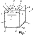
- Fig. 1 is shown in a schematic perspective view of a trained as a baking oven 1 household appliance.
- the oven 1 comprises a housing 2, in which a limited by a muffle, not shown cooking space is formed. In the oven food can be introduced for preparation.
- the cooking chamber is closed at the front by a door 3, which in Fig. 1 is shown in the closed end position. At the front of the door 3, a handle 4 is formed.
- the oven 1 comprises an operating device 5, which in the position and display only by way of example has a display unit 6 and operating elements 7 and 8.
- cooking zones 9, 10, 11 and 12 which are shown merely by way of example in terms of position and number, are likewise shown.
- the door 3 can be inserted or sunk in its lower portion 13 in the housing 2, resulting in the transfer of the door 3 of the in Fig. 1 shown closed end position in the fully open end position is the case.
- the door 3 is then inserted sunk into a free space of the housing 2, which is formed by this space arranged below the cooking chamber and separated by this by a corresponding partition wall storage space 14.
- the door 3 is connected to exemplarily shown and marked door hinges 15 and 16 and pivotable about this and in said storage space 14 retractable and extendable.
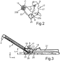
- Fig. 2 is a side view of a bearing unit 17 is shown, which is designed as a U-shaped bracket.
- the hinge unit 17 represents a hinge hook of a hinge 15 or 16.
- the hinges 15 and 16 are of identical design and functionally identical, so that the following explanation of one of the two hinges also applies to the other.
- the hinges 15 and 16 have in addition to a respectively provided storage unit 17 and a hinge housing, which is not shown here in detail. These hinges 15 and 16 are each a guide device 18 (FIG. Fig. 3 ) associated with the components and the functions. The door 3 is guided by means of these guide devices 18 and thereby coupled accordingly, so that it is in the storage space 14 in and out of the storage space 14.
- the bearing unit 17 comprises a fulcrum, which on a rotation axis A, which in Fig. 2 extends perpendicular to the plane of the figure, is arranged. At this axis of rotation A, the bearing unit 17 is also connected to the hinge housing and pivotable relative to the hinge housing.
- the bearing unit 17 comprises two guide elements 19 and 20 which are designed as rollers and are mounted rotatably mounted on the bearing unit 17.
- the bearing unit 17 comprises a first bracket leg 21, which is the hinge pivot point or having the axis of rotation A. It also includes a second bracket leg 22, on which the two guide elements 19 and 20 are arranged.
- the bearing unit 17 is rigid in its U-shaped bracket, that is, the two bracket legs 21 and 22 are not movable relative to each other.
- the second guide element 20 is rotatably mounted about a rotation axis B.
- the first guide element 19 is rotatable about an axis C, which extends parallel to the axis A and to the axis B itself.
- the axis C has a distance a1 to the axis A and the axis B has a distance a2 to the axis A.
- the second bracket leg 22 can thus be pivoted back and forth along the arrow P about the axis B.
- the first guide member 19 is disposed at an upper free end 25a of the second stirrup leg 22, and the second guide member 20 is disposed at an end 25b of the second stirrup leg 22 opposite the free end 25a.
- a vertical height h is shown, which represents the extension of a technical part 26, which is the guide device 18 associated.
- the engineering part 26 describes a component which also has a groove or a guide track 27 in which the guide elements 19 and 20 are guided into the storage space 14 when the door 3 is inserted.
- a slide carriage 28 is also provided, which slides in the guideway 27 and the guide device 18 is associated.
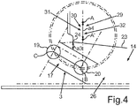
- Fig. 4 is an enlarged partial sectional view of the oven 1 is shown in a schematic side view, in which case a front lower portion is shown.
- a vertical distance a3 between the intermediate bottom 23 and an inner side of the door 3 is present, which can be achieved by a previous vertical displacement of the axis of rotation A before the actual pivoting movement and thus the retraction of the door 3 in the storage space 14.
- This distance a3 would not exist without such a vertical displacement of the axis of rotation A at this height and thus only a smaller distance.
- this first movement part of the door 3 Starting from this horizontal position position is then carried out at an opening initiation of the door 3 by a first movement part of the door 3, a vertical displacement.
- this first partial movement path starting from the fully closed position of the door 3rd measured and up to an opening angle less than 15 °, in particular less than 10 °, is sufficient.
- only a vertical movement of the door 3 is carried out on this first partial movement path, and the possibly minimal pivoting of the door 3 in the sense is negligible.
- the guide device 18 comprises for the horizontal displacement of the door 3 and at least some components of the guide device 18, in particular the bearing unit 17, a displacement device 29, which in Fig. 4 is indicated only with the corresponding reference numerals, but component-specific not shown in detail.
- this displacement device 29 is preferably carried out only a vertical change in position of the axis of rotation A on a displacement path 30.
- the displacement path 30 has a maximum length of a4. This displacement path 30 is in particular less than 9 cm, in particular less than or equal to 8 cm, preferably between 1 cm and 8 cm.
- a retraction of the door 3 into the storage space 14 is then carried out on a subsequent second movement partial path which, together with the first movement partial path, defines the total movement path of the door 3 from the completely closed position to the completely open position.
- the vertical position is achieved at the end of it, that it is displaced in position, so that this through the axis of rotation A 'in Fig. 4 is marked.
- the pivoting movement of the door 3 is performed on the second movement part path and then carried out the retraction into the storage space 14.
- Fig. 4 In this case, a snapshot is shown, in which the door 3 is already located on the second movement partial path and has already been pivoted, so that it has already moved easily into the storage space 14.
- the movement of the bearing unit 17 to the rear into the stowage space 14 is likewise accomplished during this retraction into the stowage space 14 and this is achieved via the carriage 28.
- a release device 32 automatically is solvable.
- This release device 32 is also shown with a reference numeral, the clarity serving in Fig. 4 but not shown in detail.
- a stop is formed, through which a forwardly pulled out end position of the door 3, as it is reached at the end of the first movement part path, is predetermined.
- this hinge pivot point or the axis of rotation of the bearing unit 17 can thus either generally, which means that it is fixed and no longer displaceable before the opening movement of the door 3 or during the opening movement is performed as part of the movement.
- this hinge pivot point can thus change its vertical position at a certain point in time.
- a vertical distance a3 is increased in comparison to a design without such a height-adjustability of the axis of rotation and thus permits a reduction of the space in the engineering part 26.
Landscapes
- Engineering & Computer Science (AREA)
- Chemical & Material Sciences (AREA)
- Combustion & Propulsion (AREA)
- Mechanical Engineering (AREA)
- General Engineering & Computer Science (AREA)
- Cabinets, Racks, Or The Like Of Rigid Construction (AREA)
- Closing And Opening Devices For Wings, And Checks For Wings (AREA)
- Hinges (AREA)
Claims (15)
- Appareil électroménager (1) avec un corps (2) entourant un espace de placement et avec une porte (3) avec laquelle une ouverture de chargement de l'espace de placement peut être refermée et qui est disposée de manière relativement pivotante par rapport au corps (2) et à l'état ouvert peut être escamotée dans un espace de rangement (14) dans le corps (2), cette porte (3) étant couplée avec un dispositif de guidage (18), grâce auquel le mouvement dans et hors de l'espace de rangement (14) est guidé, et ce dispositif de guidage (18) présentant au moins une unité de pose (17), laquelle est logée à rotation autour d'un axe rotatif (A) et sur laquelle des éléments de guidage (19, 20) sont disposés, caractérisé en ce que cette unité de pose (17) est un talon de charnière, lequel est couplé par un axe de rotation (A) avec le corps de charnière et peut être tourné avec l'axe de rotation (A) relativement au corps de charnière, et en ce que le dispositif de guidage (18) est réalisé de telle façon que l'axe de rotation (A) de l'unité de pose (17) peut être décalé sur une trajectoire de décalage (30) dans le sens vertical et ainsi la pose en hauteur de l'axe de rotation (A) peut être modifiée par rapport à l'espace de rangement (14).
- Appareil électroménager (1) selon la revendication 1, caractérisé en ce que le décalage vertical de l'axe de rotation (A) s'effectue sur une première trajectoire de mouvement partielle d'une trajectoire de mouvement complète de la porte (3) se mesurant entre une position ouverte et une fermée de la porte (3).
- Appareil électroménager (1) selon la revendication 2, caractérisé en ce que la première trajectoire de mouvement partielle se mesure à partir de la position fermée de la porte (3) et va jusqu'à un angle d'ouverture inférieur à 15°, en particulier inférieur à 10°.
- Appareil électroménager (1) selon la revendication 2 ou 3, caractérisé en ce qu'un mouvement de rotation de l'unité de pose (17) autour de l'axe de rotation (A) est bloqué sur la première trajectoire de mouvement partielle par un dispositif de blocage (31).
- Appareil électroménager (1) selon l'une des revendications 2 à 4, caractérisé en ce que, sur la première trajectoire de mouvement partielle, une entrée de la porte (2) dans l'espace de rangement (14) est empêchée.
- Appareil électroménager (1) selon l'une des revendications 2 à 5, caractérisé en ce que la trajectoire de mouvement complète de la porte (3) présente une deuxième trajectoire de mouvement partielle - qui suit la première trajectoire de mouvement - sur laquelle la porte (3) entre dans l'espace de rangement (14).
- Appareil électroménager (1) selon la revendication 6, caractérisé en ce que sur une transition entre les trajectoires de mouvement partielles, l'état bloqué antirotation de l'unité de pose (17) peut se défaire automatiquement par un dispositif de libération (32).
- Appareil électroménager (1) selon l'une des revendications 2 à 7, caractérisé en ce que, une butée est réalisée, par laquelle une position finale de la porte (3) décalée verticalement vers le bas est prédéfinie avec l'unité de pose (17) à l'extrémité de la première trajectoire de mouvement partielle.
- Appareil électroménager (1) selon la revendication 1, caractérisé en ce que le décalage vertical de l'axe de rotation (A) peut se faire avant l'ouverture de la porte (3).
- Appareil électroménager (1) selon l'une des revendications précédentes, caractérisé en ce que la trajectoire de décalage (30) est inférieure à 5 cm, en particulier inférieure à 3 cm.
- Appareil électroménager (1) selon l'une des revendications précédentes, caractérisé en ce que l'unité de pose (17) présente un étrier en U et l'axe de rotation (A) est réalisé sur un premier montant d'étrier (21) et les éléments de guidage (19, 20) sont disposés sur un deuxième montant d'étrier (22).
- Appareil électroménager (1) selon l'une des revendications précédentes, caractérisé en ce que les éléments de guidage (19, 20) sont disposés rotatifs sur l'unité de pose (17), en particulier les éléments de guidage (19, 20) sont des rouleaux.
- Procédé d'ouverture et de fermeture d'une porte (3) d'un appareil électroménager (1), lequel est réalisé à l'aide d'un corps (2) entourant un espace de placement, et d'une porte (3) pouvant fermer l'ouverture de chargement de l'espace de placement et qui est agencé de manière relativement pivotante par rapport au corps (2), et à l'état ouvert est escamoté dans un espace de rangement (14) dans le corps (2), cette porte (3) étant couplée à un dispositif de guidage (18), avec lequel le guidage de mouvement dans et hors de l'espace de rangement (14) est guidé, et ce dispositif de guidage (18) présente au moins une unité de pose (17), logée rotative autour d'un axe de rotation (A) et à laquelle des éléments de guidage (19, 20) sont disposés, caractérisé en ce que l'unité de pose (17) est un talon de charnière qui, par l'axe de rotation (A) est couplé à un corps de charnière et peut être tourné avec l'axe de rotation (A) relativement au corps de charnière et en ce que l'axe de rotation (A) de l'unité de pose (17) est décalé sur une trajectoire de décalage (30) dans le sens vertical et ainsi la pose en hauteur de l'axe de rotation (A) par rapport à l'espace de rangement (14) est modifiée.
- Procédé selon la revendication 13, caractérisé en ce que le décalage vertical de l'axe de rotation (A) s'effectue sur une première trajectoire de mouvement partielle d'une trajectoire de mouvement complète de la porte (3) se mesurant entre une position ouverte et une fermée de la porte (3).
- Procédé selon la revendication 14, caractérisé en ce qu'un mouvement de rotation de l'unité de pose (17) autour de l'axe de rotation (A) est bloqué sur la première trajectoire de mouvement partielle par un dispositif de blocage (31) et/ou sur la première trajectoire de mouvement partielle, une entrée de la porte (3) dans l'espace de rangement (14) est empêchée.
Applications Claiming Priority (1)
| Application Number | Priority Date | Filing Date | Title |
|---|---|---|---|
| DE102013225403.2A DE102013225403A1 (de) | 2013-12-10 | 2013-12-10 | Haushaltsgerät mit einer in einem Verstauraum versenkbaren Tür mit vertikaler Lageveränderungsmöglichkeit einer Drehachse einer Lagereinheit sowie Verfahren zum öffnen und Schließen einer Tür |
Publications (2)
| Publication Number | Publication Date |
|---|---|
| EP2930436A1 EP2930436A1 (fr) | 2015-10-14 |
| EP2930436B1 true EP2930436B1 (fr) | 2019-06-05 |
Family
ID=52000741
Family Applications (1)
| Application Number | Title | Priority Date | Filing Date |
|---|---|---|---|
| EP14195684.7A Active EP2930436B1 (fr) | 2013-12-10 | 2014-12-01 | Appareil ménager doté d'une porte escamotable et procédé d'ouverture et de fermeture d'une porte d'appareil ménager |
Country Status (2)
| Country | Link |
|---|---|
| EP (1) | EP2930436B1 (fr) |
| DE (1) | DE102013225403A1 (fr) |
Families Citing this family (1)
| Publication number | Priority date | Publication date | Assignee | Title |
|---|---|---|---|---|
| DE102018214046A1 (de) * | 2018-08-21 | 2020-02-27 | BSH Hausgeräte GmbH | Gargerät mit einer spezifischen Führungsvorrichtung für eine versenkbare Tür |
Family Cites Families (8)
| Publication number | Priority date | Publication date | Assignee | Title |
|---|---|---|---|---|
| DE1800425U (de) * | 1959-09-24 | 1959-11-19 | Alfred Dr Neff | Backofentuer. |
| US3127889A (en) * | 1960-09-23 | 1964-04-07 | Mills Prod Inc | Oven closure and hinge construction |
| NO170884C (no) | 1986-08-18 | 1992-12-23 | Hoffmann La Roche | Analogifremgangsmaate ved fremstilling av terapeutisk aktive pyrimidinderivater |
| DE19906913C2 (de) * | 1999-02-19 | 2000-12-21 | Schott Glas | Tür für ein Küchengerät |
| DE10208490A1 (de) * | 2002-02-27 | 2004-02-05 | BSH Bosch und Siemens Hausgeräte GmbH | Haushaltsgerät |
| DE102006002409A1 (de) * | 2006-01-18 | 2007-07-19 | BSH Bosch und Siemens Hausgeräte GmbH | Vorrichtung mit einer Tür |
| DE102008010526A1 (de) | 2008-02-22 | 2009-08-27 | BSH Bosch und Siemens Hausgeräte GmbH | Hausgerätvorrichtung |
| DE102011083512A1 (de) | 2011-09-27 | 2013-03-28 | BSH Bosch und Siemens Hausgeräte GmbH | Haushaltsgerät mit einem Aufnahmeraum und einer Tür zum Verschließen des Aufnahmeraums, sowie Verfahren zum Betätigen einer Tür eines Haushaltsgeräts |
-
2013
- 2013-12-10 DE DE102013225403.2A patent/DE102013225403A1/de not_active Withdrawn
-
2014
- 2014-12-01 EP EP14195684.7A patent/EP2930436B1/fr active Active
Non-Patent Citations (1)
| Title |
|---|
| None * |
Also Published As
| Publication number | Publication date |
|---|---|
| DE102013225403A1 (de) | 2015-06-11 |
| EP2930436A1 (fr) | 2015-10-14 |
Similar Documents
| Publication | Publication Date | Title |
|---|---|---|
| EP2250929B1 (fr) | Elément d'armoire doté d'un élément de sortie rétractable | |
| DE102021111434B4 (de) | System, umfassend ein Möbel mit einer Einbaunische und ein Einbaugerät, und Verfahren zum Betrieb des Systems | |
| EP3668351B1 (fr) | Glissière de sortie pour tiroir | |
| EP3654803B2 (fr) | Meuble avec une machine à café ou un grille-pain et procédé d'ouverture d'une porte | |
| EP3622223B1 (fr) | Appareil de cuisson équipé d'un dispositif de traction par câble pour le pivotement automatique d'une porte | |
| EP2574712A1 (fr) | Appareil ménager avec une cavité et une porte de fermeture de la cavité et procédé d'actionnement d'une porte d'un appareil ménager | |
| DE102010007129A1 (de) | Beschlag für Eckschränke | |
| EP2540940B1 (fr) | Articulation pour une porte d'un appareil ménager, porte avec une telle articulation et appareil ménager doté d'une articulation correspondante ainsi qu'un procédé d'actionnement d'une poignée de porte | |
| WO2011094788A1 (fr) | Système de tiroir | |
| EP3838068A1 (fr) | Guidage d'extension de tiroir | |
| EP2362044A2 (fr) | Appareil ménager, notamment four de cuisson, et procédé de déplacement d'une porte | |
| DE102015206576A1 (de) | Haushaltsgerät mit einer in einem Verstauraum versenkbaren Tür mit spezifischer Lagereinheit | |
| EP2636340B1 (fr) | Dispositif de guidage pour guider une partie de meuble mobile par rapport à un corps de meuble | |
| EP3658824B1 (fr) | Appareil de cuisson muni d'une porte escamotable qui présente un ressort de retenue spécifique pour un coussinet de palier | |
| DE102018201950A1 (de) | Gargerät mit einem Technikteil für eine versenkbare Tür, welches eine Führungsbahn in einer oberen Höhenhälfte des Technikteils aufweist | |
| EP2884188B1 (fr) | Appareil ménager doté d'une porte escamotable dans un espace de rangement et d'un axe de rotation déplaçable en translation d'une unité de roulement et procédé d'ouverture et de fermeture d'une telle porte | |
| DE102015206577B4 (de) | Haushaltsgerät mit einer in einem Verstauraum versenkbaren Tür mit elliptischer Kulisse zur Bewegung eines Lagerbügels einer Tür-Lagereinheit | |
| EP2189726B1 (fr) | Poignée escamotable pour une porte d'un appareil ménager et porte d'un appareil ménager doté d'une telle poignée | |
| DE102016215649B4 (de) | Haushaltsgerät mit einer Schwenk-Schiebetür | |
| DE102015222796A1 (de) | Gargerät mit spezifisch bewegbarer Tür | |
| EP2930436B1 (fr) | Appareil ménager doté d'une porte escamotable et procédé d'ouverture et de fermeture d'une porte d'appareil ménager | |
| EP3928036B1 (fr) | Appareil de cuisson muni d'une unité d'amortissement spécifique entre des glissières d'un dispositif de guidage pour une porte escamotable | |
| EP2884189B1 (fr) | Appareil ménager doté d'une porte pouvant être entrée dans un espace de rangement et procédé d'ouverture et de fermeture d'une porte d'un appareil ménager | |
| WO2023194080A1 (fr) | Appareil ménager doté d'un système d'accouplement-coulissement spécifique pour une porte abaissable et procédé | |
| DE102012222028A1 (de) | Haltevorrichtung für einen Gargutträger sowie Gargerät mit einer derartigen Haltevorrichtung |
Legal Events
| Date | Code | Title | Description |
|---|---|---|---|
| PUAI | Public reference made under article 153(3) epc to a published international application that has entered the european phase |
Free format text: ORIGINAL CODE: 0009012 |
|
| AK | Designated contracting states |
Kind code of ref document: A1 Designated state(s): AL AT BE BG CH CY CZ DE DK EE ES FI FR GB GR HR HU IE IS IT LI LT LU LV MC MK MT NL NO PL PT RO RS SE SI SK SM TR |
|
| AX | Request for extension of the european patent |
Extension state: BA ME |
|
| 17P | Request for examination filed |
Effective date: 20160414 |
|
| RBV | Designated contracting states (corrected) |
Designated state(s): AL AT BE BG CH CY CZ DE DK EE ES FI FR GB GR HR HU IE IS IT LI LT LU LV MC MK MT NL NO PL PT RO RS SE SI SK SM TR |
|
| GRAP | Despatch of communication of intention to grant a patent |
Free format text: ORIGINAL CODE: EPIDOSNIGR1 |
|
| STAA | Information on the status of an ep patent application or granted ep patent |
Free format text: STATUS: GRANT OF PATENT IS INTENDED |
|
| INTG | Intention to grant announced |
Effective date: 20190115 |
|
| GRAS | Grant fee paid |
Free format text: ORIGINAL CODE: EPIDOSNIGR3 |
|
| GRAA | (expected) grant |
Free format text: ORIGINAL CODE: 0009210 |
|
| STAA | Information on the status of an ep patent application or granted ep patent |
Free format text: STATUS: THE PATENT HAS BEEN GRANTED |
|
| AK | Designated contracting states |
Kind code of ref document: B1 Designated state(s): AL AT BE BG CH CY CZ DE DK EE ES FI FR GB GR HR HU IE IS IT LI LT LU LV MC MK MT NL NO PL PT RO RS SE SI SK SM TR |
|
| REG | Reference to a national code |
Ref country code: GB Ref legal event code: FG4D Free format text: NOT ENGLISH |
|
| REG | Reference to a national code |
Ref country code: CH Ref legal event code: EP |
|
| REG | Reference to a national code |
Ref country code: AT Ref legal event code: REF Ref document number: 1140397 Country of ref document: AT Kind code of ref document: T Effective date: 20190615 |
|
| REG | Reference to a national code |
Ref country code: DE Ref legal event code: R096 Ref document number: 502014011841 Country of ref document: DE |
|
| REG | Reference to a national code |
Ref country code: IE Ref legal event code: FG4D Free format text: LANGUAGE OF EP DOCUMENT: GERMAN |
|
| REG | Reference to a national code |
Ref country code: NL Ref legal event code: MP Effective date: 20190605 |
|
| REG | Reference to a national code |
Ref country code: LT Ref legal event code: MG4D |
|
| PG25 | Lapsed in a contracting state [announced via postgrant information from national office to epo] |
Ref country code: FI Free format text: LAPSE BECAUSE OF FAILURE TO SUBMIT A TRANSLATION OF THE DESCRIPTION OR TO PAY THE FEE WITHIN THE PRESCRIBED TIME-LIMIT Effective date: 20190605 Ref country code: NO Free format text: LAPSE BECAUSE OF FAILURE TO SUBMIT A TRANSLATION OF THE DESCRIPTION OR TO PAY THE FEE WITHIN THE PRESCRIBED TIME-LIMIT Effective date: 20190905 Ref country code: HR Free format text: LAPSE BECAUSE OF FAILURE TO SUBMIT A TRANSLATION OF THE DESCRIPTION OR TO PAY THE FEE WITHIN THE PRESCRIBED TIME-LIMIT Effective date: 20190605 Ref country code: LT Free format text: LAPSE BECAUSE OF FAILURE TO SUBMIT A TRANSLATION OF THE DESCRIPTION OR TO PAY THE FEE WITHIN THE PRESCRIBED TIME-LIMIT Effective date: 20190605 Ref country code: ES Free format text: LAPSE BECAUSE OF FAILURE TO SUBMIT A TRANSLATION OF THE DESCRIPTION OR TO PAY THE FEE WITHIN THE PRESCRIBED TIME-LIMIT Effective date: 20190605 Ref country code: AL Free format text: LAPSE BECAUSE OF FAILURE TO SUBMIT A TRANSLATION OF THE DESCRIPTION OR TO PAY THE FEE WITHIN THE PRESCRIBED TIME-LIMIT Effective date: 20190605 Ref country code: SE Free format text: LAPSE BECAUSE OF FAILURE TO SUBMIT A TRANSLATION OF THE DESCRIPTION OR TO PAY THE FEE WITHIN THE PRESCRIBED TIME-LIMIT Effective date: 20190605 |
|
| PG25 | Lapsed in a contracting state [announced via postgrant information from national office to epo] |
Ref country code: LV Free format text: LAPSE BECAUSE OF FAILURE TO SUBMIT A TRANSLATION OF THE DESCRIPTION OR TO PAY THE FEE WITHIN THE PRESCRIBED TIME-LIMIT Effective date: 20190605 Ref country code: GR Free format text: LAPSE BECAUSE OF FAILURE TO SUBMIT A TRANSLATION OF THE DESCRIPTION OR TO PAY THE FEE WITHIN THE PRESCRIBED TIME-LIMIT Effective date: 20190906 Ref country code: RS Free format text: LAPSE BECAUSE OF FAILURE TO SUBMIT A TRANSLATION OF THE DESCRIPTION OR TO PAY THE FEE WITHIN THE PRESCRIBED TIME-LIMIT Effective date: 20190605 Ref country code: BG Free format text: LAPSE BECAUSE OF FAILURE TO SUBMIT A TRANSLATION OF THE DESCRIPTION OR TO PAY THE FEE WITHIN THE PRESCRIBED TIME-LIMIT Effective date: 20190905 |
|
| PG25 | Lapsed in a contracting state [announced via postgrant information from national office to epo] |
Ref country code: SK Free format text: LAPSE BECAUSE OF FAILURE TO SUBMIT A TRANSLATION OF THE DESCRIPTION OR TO PAY THE FEE WITHIN THE PRESCRIBED TIME-LIMIT Effective date: 20190605 Ref country code: CZ Free format text: LAPSE BECAUSE OF FAILURE TO SUBMIT A TRANSLATION OF THE DESCRIPTION OR TO PAY THE FEE WITHIN THE PRESCRIBED TIME-LIMIT Effective date: 20190605 Ref country code: RO Free format text: LAPSE BECAUSE OF FAILURE TO SUBMIT A TRANSLATION OF THE DESCRIPTION OR TO PAY THE FEE WITHIN THE PRESCRIBED TIME-LIMIT Effective date: 20190605 Ref country code: PT Free format text: LAPSE BECAUSE OF FAILURE TO SUBMIT A TRANSLATION OF THE DESCRIPTION OR TO PAY THE FEE WITHIN THE PRESCRIBED TIME-LIMIT Effective date: 20191007 Ref country code: NL Free format text: LAPSE BECAUSE OF FAILURE TO SUBMIT A TRANSLATION OF THE DESCRIPTION OR TO PAY THE FEE WITHIN THE PRESCRIBED TIME-LIMIT Effective date: 20190605 Ref country code: EE Free format text: LAPSE BECAUSE OF FAILURE TO SUBMIT A TRANSLATION OF THE DESCRIPTION OR TO PAY THE FEE WITHIN THE PRESCRIBED TIME-LIMIT Effective date: 20190605 |
|
| PG25 | Lapsed in a contracting state [announced via postgrant information from national office to epo] |
Ref country code: IT Free format text: LAPSE BECAUSE OF FAILURE TO SUBMIT A TRANSLATION OF THE DESCRIPTION OR TO PAY THE FEE WITHIN THE PRESCRIBED TIME-LIMIT Effective date: 20190605 Ref country code: SM Free format text: LAPSE BECAUSE OF FAILURE TO SUBMIT A TRANSLATION OF THE DESCRIPTION OR TO PAY THE FEE WITHIN THE PRESCRIBED TIME-LIMIT Effective date: 20190605 Ref country code: IS Free format text: LAPSE BECAUSE OF FAILURE TO SUBMIT A TRANSLATION OF THE DESCRIPTION OR TO PAY THE FEE WITHIN THE PRESCRIBED TIME-LIMIT Effective date: 20191005 |
|
| REG | Reference to a national code |
Ref country code: DE Ref legal event code: R097 Ref document number: 502014011841 Country of ref document: DE |
|
| PG25 | Lapsed in a contracting state [announced via postgrant information from national office to epo] |
Ref country code: TR Free format text: LAPSE BECAUSE OF FAILURE TO SUBMIT A TRANSLATION OF THE DESCRIPTION OR TO PAY THE FEE WITHIN THE PRESCRIBED TIME-LIMIT Effective date: 20190605 |
|
| PLBE | No opposition filed within time limit |
Free format text: ORIGINAL CODE: 0009261 |
|
| STAA | Information on the status of an ep patent application or granted ep patent |
Free format text: STATUS: NO OPPOSITION FILED WITHIN TIME LIMIT |
|
| PG25 | Lapsed in a contracting state [announced via postgrant information from national office to epo] |
Ref country code: PL Free format text: LAPSE BECAUSE OF FAILURE TO SUBMIT A TRANSLATION OF THE DESCRIPTION OR TO PAY THE FEE WITHIN THE PRESCRIBED TIME-LIMIT Effective date: 20190605 Ref country code: DK Free format text: LAPSE BECAUSE OF FAILURE TO SUBMIT A TRANSLATION OF THE DESCRIPTION OR TO PAY THE FEE WITHIN THE PRESCRIBED TIME-LIMIT Effective date: 20190605 |
|
| 26N | No opposition filed |
Effective date: 20200306 |
|
| PG25 | Lapsed in a contracting state [announced via postgrant information from national office to epo] |
Ref country code: SI Free format text: LAPSE BECAUSE OF FAILURE TO SUBMIT A TRANSLATION OF THE DESCRIPTION OR TO PAY THE FEE WITHIN THE PRESCRIBED TIME-LIMIT Effective date: 20190605 |
|
| REG | Reference to a national code |
Ref country code: CH Ref legal event code: PL |
|
| REG | Reference to a national code |
Ref country code: BE Ref legal event code: MM Effective date: 20191231 |
|
| PG25 | Lapsed in a contracting state [announced via postgrant information from national office to epo] |
Ref country code: MC Free format text: LAPSE BECAUSE OF FAILURE TO SUBMIT A TRANSLATION OF THE DESCRIPTION OR TO PAY THE FEE WITHIN THE PRESCRIBED TIME-LIMIT Effective date: 20190605 |
|
| PG25 | Lapsed in a contracting state [announced via postgrant information from national office to epo] |
Ref country code: IE Free format text: LAPSE BECAUSE OF NON-PAYMENT OF DUE FEES Effective date: 20191201 Ref country code: LU Free format text: LAPSE BECAUSE OF NON-PAYMENT OF DUE FEES Effective date: 20191201 Ref country code: FR Free format text: LAPSE BECAUSE OF NON-PAYMENT OF DUE FEES Effective date: 20191231 |
|
| PG25 | Lapsed in a contracting state [announced via postgrant information from national office to epo] |
Ref country code: CH Free format text: LAPSE BECAUSE OF NON-PAYMENT OF DUE FEES Effective date: 20191231 Ref country code: BE Free format text: LAPSE BECAUSE OF NON-PAYMENT OF DUE FEES Effective date: 20191231 Ref country code: LI Free format text: LAPSE BECAUSE OF NON-PAYMENT OF DUE FEES Effective date: 20191231 |
|
| REG | Reference to a national code |
Ref country code: AT Ref legal event code: MM01 Ref document number: 1140397 Country of ref document: AT Kind code of ref document: T Effective date: 20191201 |
|
| PG25 | Lapsed in a contracting state [announced via postgrant information from national office to epo] |
Ref country code: CY Free format text: LAPSE BECAUSE OF FAILURE TO SUBMIT A TRANSLATION OF THE DESCRIPTION OR TO PAY THE FEE WITHIN THE PRESCRIBED TIME-LIMIT Effective date: 20190605 Ref country code: AT Free format text: LAPSE BECAUSE OF NON-PAYMENT OF DUE FEES Effective date: 20191201 |
|
| PG25 | Lapsed in a contracting state [announced via postgrant information from national office to epo] |
Ref country code: MT Free format text: LAPSE BECAUSE OF FAILURE TO SUBMIT A TRANSLATION OF THE DESCRIPTION OR TO PAY THE FEE WITHIN THE PRESCRIBED TIME-LIMIT Effective date: 20190605 Ref country code: HU Free format text: LAPSE BECAUSE OF FAILURE TO SUBMIT A TRANSLATION OF THE DESCRIPTION OR TO PAY THE FEE WITHIN THE PRESCRIBED TIME-LIMIT; INVALID AB INITIO Effective date: 20141201 |
|
| PG25 | Lapsed in a contracting state [announced via postgrant information from national office to epo] |
Ref country code: MK Free format text: LAPSE BECAUSE OF FAILURE TO SUBMIT A TRANSLATION OF THE DESCRIPTION OR TO PAY THE FEE WITHIN THE PRESCRIBED TIME-LIMIT Effective date: 20190605 |
|
| REG | Reference to a national code |
Ref country code: DE Ref legal event code: R084 Ref document number: 502014011841 Country of ref document: DE |
|
| PGFP | Annual fee paid to national office [announced via postgrant information from national office to epo] |
Ref country code: GB Payment date: 20251218 Year of fee payment: 12 |
|
| PGFP | Annual fee paid to national office [announced via postgrant information from national office to epo] |
Ref country code: DE Payment date: 20251231 Year of fee payment: 12 |