EP2189762A2 - Konfiguration zur Erzeugung eines Referenzsignals für ein interferometrisches Miniatur-Rasterungskodiergerät mithilfe von Glasfaserempfangskanälen - Google Patents
Konfiguration zur Erzeugung eines Referenzsignals für ein interferometrisches Miniatur-Rasterungskodiergerät mithilfe von Glasfaserempfangskanälen Download PDFInfo
- Publication number
- EP2189762A2 EP2189762A2 EP09176651A EP09176651A EP2189762A2 EP 2189762 A2 EP2189762 A2 EP 2189762A2 EP 09176651 A EP09176651 A EP 09176651A EP 09176651 A EP09176651 A EP 09176651A EP 2189762 A2 EP2189762 A2 EP 2189762A2
- Authority
- EP
- European Patent Office
- Prior art keywords
- reference mark
- fiber optic
- scale
- signal receiver
- signal
- Prior art date
- Legal status (The legal status is an assumption and is not a legal conclusion. Google has not performed a legal analysis and makes no representation as to the accuracy of the status listed.)
- Withdrawn
Links
- 239000000835 fiber Substances 0.000 title claims abstract description 257
- 230000000737 periodic effect Effects 0.000 claims abstract description 49
- 239000013307 optical fiber Substances 0.000 claims description 119
- 230000000694 effects Effects 0.000 claims description 83
- 238000005259 measurement Methods 0.000 claims description 56
- 239000011295 pitch Substances 0.000 claims description 25
- 238000006073 displacement reaction Methods 0.000 claims description 23
- 230000007704 transition Effects 0.000 claims description 18
- 230000001427 coherent effect Effects 0.000 claims description 17
- 230000007423 decrease Effects 0.000 claims description 15
- 238000001914 filtration Methods 0.000 claims description 10
- 101100219315 Arabidopsis thaliana CYP83A1 gene Proteins 0.000 description 74
- 101000806846 Homo sapiens DNA-(apurinic or apyrimidinic site) endonuclease Proteins 0.000 description 74
- 101000835083 Homo sapiens Tissue factor pathway inhibitor 2 Proteins 0.000 description 74
- 101100269674 Mus musculus Alyref2 gene Proteins 0.000 description 74
- 101100140580 Saccharomyces cerevisiae (strain ATCC 204508 / S288c) REF2 gene Proteins 0.000 description 74
- 102100026134 Tissue factor pathway inhibitor 2 Human genes 0.000 description 74
- 238000013461 design Methods 0.000 description 30
- 102100036467 Protein delta homolog 1 Human genes 0.000 description 20
- 101150102995 dlk-1 gene Proteins 0.000 description 20
- 230000003287 optical effect Effects 0.000 description 20
- 238000005286 illumination Methods 0.000 description 18
- 230000000903 blocking effect Effects 0.000 description 16
- 238000010586 diagram Methods 0.000 description 8
- 238000012545 processing Methods 0.000 description 8
- 102100036284 Hepcidin Human genes 0.000 description 5
- 101001021253 Homo sapiens Hepcidin Proteins 0.000 description 5
- 230000008859 change Effects 0.000 description 5
- 238000000034 method Methods 0.000 description 5
- 238000003672 processing method Methods 0.000 description 5
- 230000008901 benefit Effects 0.000 description 4
- 102100024633 Carbonic anhydrase 2 Human genes 0.000 description 2
- 101000760643 Homo sapiens Carbonic anhydrase 2 Proteins 0.000 description 2
- 230000009286 beneficial effect Effects 0.000 description 2
- 230000000295 complement effect Effects 0.000 description 2
- 230000036039 immunity Effects 0.000 description 2
- 238000000926 separation method Methods 0.000 description 2
- 230000001629 suppression Effects 0.000 description 2
- VYZAMTAEIAYCRO-UHFFFAOYSA-N Chromium Chemical compound [Cr] VYZAMTAEIAYCRO-UHFFFAOYSA-N 0.000 description 1
- 241000669069 Chrysomphalus aonidum Species 0.000 description 1
- 230000003044 adaptive effect Effects 0.000 description 1
- 239000011248 coating agent Substances 0.000 description 1
- 238000000576 coating method Methods 0.000 description 1
- 238000012790 confirmation Methods 0.000 description 1
- 238000011109 contamination Methods 0.000 description 1
- 230000001066 destructive effect Effects 0.000 description 1
- 238000001514 detection method Methods 0.000 description 1
- 230000006872 improvement Effects 0.000 description 1
- 238000012986 modification Methods 0.000 description 1
- 230000004048 modification Effects 0.000 description 1
- 238000012544 monitoring process Methods 0.000 description 1
- 238000012856 packing Methods 0.000 description 1
- 230000000630 rising effect Effects 0.000 description 1
- 230000035945 sensitivity Effects 0.000 description 1
- 230000001360 synchronised effect Effects 0.000 description 1
Images









Classifications
-
- G—PHYSICS
- G01—MEASURING; TESTING
- G01D—MEASURING NOT SPECIALLY ADAPTED FOR A SPECIFIC VARIABLE; ARRANGEMENTS FOR MEASURING TWO OR MORE VARIABLES NOT COVERED IN A SINGLE OTHER SUBCLASS; TARIFF METERING APPARATUS; MEASURING OR TESTING NOT OTHERWISE PROVIDED FOR
- G01D5/00—Mechanical means for transferring the output of a sensing member; Means for converting the output of a sensing member to another variable where the form or nature of the sensing member does not constrain the means for converting; Transducers not specially adapted for a specific variable
- G01D5/26—Mechanical means for transferring the output of a sensing member; Means for converting the output of a sensing member to another variable where the form or nature of the sensing member does not constrain the means for converting; Transducers not specially adapted for a specific variable characterised by optical transfer means, i.e. using infrared, visible, or ultraviolet light
- G01D5/32—Mechanical means for transferring the output of a sensing member; Means for converting the output of a sensing member to another variable where the form or nature of the sensing member does not constrain the means for converting; Transducers not specially adapted for a specific variable characterised by optical transfer means, i.e. using infrared, visible, or ultraviolet light with attenuation or whole or partial obturation of beams of light
- G01D5/34—Mechanical means for transferring the output of a sensing member; Means for converting the output of a sensing member to another variable where the form or nature of the sensing member does not constrain the means for converting; Transducers not specially adapted for a specific variable characterised by optical transfer means, i.e. using infrared, visible, or ultraviolet light with attenuation or whole or partial obturation of beams of light the beams of light being detected by photocells
- G01D5/347—Mechanical means for transferring the output of a sensing member; Means for converting the output of a sensing member to another variable where the form or nature of the sensing member does not constrain the means for converting; Transducers not specially adapted for a specific variable characterised by optical transfer means, i.e. using infrared, visible, or ultraviolet light with attenuation or whole or partial obturation of beams of light the beams of light being detected by photocells using displacement encoding scales
- G01D5/34707—Scales; Discs, e.g. fixation, fabrication, compensation
- G01D5/34715—Scale reading or illumination devices
- G01D5/34723—Scale reading or illumination devices involving light-guides
-
- G—PHYSICS
- G01—MEASURING; TESTING
- G01D—MEASURING NOT SPECIALLY ADAPTED FOR A SPECIFIC VARIABLE; ARRANGEMENTS FOR MEASURING TWO OR MORE VARIABLES NOT COVERED IN A SINGLE OTHER SUBCLASS; TARIFF METERING APPARATUS; MEASURING OR TESTING NOT OTHERWISE PROVIDED FOR
- G01D5/00—Mechanical means for transferring the output of a sensing member; Means for converting the output of a sensing member to another variable where the form or nature of the sensing member does not constrain the means for converting; Transducers not specially adapted for a specific variable
- G01D5/26—Mechanical means for transferring the output of a sensing member; Means for converting the output of a sensing member to another variable where the form or nature of the sensing member does not constrain the means for converting; Transducers not specially adapted for a specific variable characterised by optical transfer means, i.e. using infrared, visible, or ultraviolet light
- G01D5/268—Mechanical means for transferring the output of a sensing member; Means for converting the output of a sensing member to another variable where the form or nature of the sensing member does not constrain the means for converting; Transducers not specially adapted for a specific variable characterised by optical transfer means, i.e. using infrared, visible, or ultraviolet light using optical fibres
-
- G—PHYSICS
- G01—MEASURING; TESTING
- G01D—MEASURING NOT SPECIALLY ADAPTED FOR A SPECIFIC VARIABLE; ARRANGEMENTS FOR MEASURING TWO OR MORE VARIABLES NOT COVERED IN A SINGLE OTHER SUBCLASS; TARIFF METERING APPARATUS; MEASURING OR TESTING NOT OTHERWISE PROVIDED FOR
- G01D5/00—Mechanical means for transferring the output of a sensing member; Means for converting the output of a sensing member to another variable where the form or nature of the sensing member does not constrain the means for converting; Transducers not specially adapted for a specific variable
- G01D5/26—Mechanical means for transferring the output of a sensing member; Means for converting the output of a sensing member to another variable where the form or nature of the sensing member does not constrain the means for converting; Transducers not specially adapted for a specific variable characterised by optical transfer means, i.e. using infrared, visible, or ultraviolet light
- G01D5/32—Mechanical means for transferring the output of a sensing member; Means for converting the output of a sensing member to another variable where the form or nature of the sensing member does not constrain the means for converting; Transducers not specially adapted for a specific variable characterised by optical transfer means, i.e. using infrared, visible, or ultraviolet light with attenuation or whole or partial obturation of beams of light
- G01D5/34—Mechanical means for transferring the output of a sensing member; Means for converting the output of a sensing member to another variable where the form or nature of the sensing member does not constrain the means for converting; Transducers not specially adapted for a specific variable characterised by optical transfer means, i.e. using infrared, visible, or ultraviolet light with attenuation or whole or partial obturation of beams of light the beams of light being detected by photocells
- G01D5/347—Mechanical means for transferring the output of a sensing member; Means for converting the output of a sensing member to another variable where the form or nature of the sensing member does not constrain the means for converting; Transducers not specially adapted for a specific variable characterised by optical transfer means, i.e. using infrared, visible, or ultraviolet light with attenuation or whole or partial obturation of beams of light the beams of light being detected by photocells using displacement encoding scales
- G01D5/34746—Linear encoders
-
- G—PHYSICS
- G01—MEASURING; TESTING
- G01D—MEASURING NOT SPECIALLY ADAPTED FOR A SPECIFIC VARIABLE; ARRANGEMENTS FOR MEASURING TWO OR MORE VARIABLES NOT COVERED IN A SINGLE OTHER SUBCLASS; TARIFF METERING APPARATUS; MEASURING OR TESTING NOT OTHERWISE PROVIDED FOR
- G01D5/00—Mechanical means for transferring the output of a sensing member; Means for converting the output of a sensing member to another variable where the form or nature of the sensing member does not constrain the means for converting; Transducers not specially adapted for a specific variable
- G01D5/26—Mechanical means for transferring the output of a sensing member; Means for converting the output of a sensing member to another variable where the form or nature of the sensing member does not constrain the means for converting; Transducers not specially adapted for a specific variable characterised by optical transfer means, i.e. using infrared, visible, or ultraviolet light
- G01D5/32—Mechanical means for transferring the output of a sensing member; Means for converting the output of a sensing member to another variable where the form or nature of the sensing member does not constrain the means for converting; Transducers not specially adapted for a specific variable characterised by optical transfer means, i.e. using infrared, visible, or ultraviolet light with attenuation or whole or partial obturation of beams of light
- G01D5/34—Mechanical means for transferring the output of a sensing member; Means for converting the output of a sensing member to another variable where the form or nature of the sensing member does not constrain the means for converting; Transducers not specially adapted for a specific variable characterised by optical transfer means, i.e. using infrared, visible, or ultraviolet light with attenuation or whole or partial obturation of beams of light the beams of light being detected by photocells
- G01D5/36—Forming the light into pulses
- G01D5/366—Particular pulse shapes
Definitions
- This invention relates generally to displacement sensing optical encoders, and more particularly to providing a reference signal for a miniature fiber optic encoder utilizing optical fibers as receiver elements.
- Many motion control and/or position measurement systems include provisions for inputting a reference signal that is usable to identify a particular period within a grating scale.
- the reference signal generally corresponding to a feature that is fixed relative to the grating scale, provides a reference point that eliminates the position ambiguities that may otherwise arise in incremental type displacement measuring systems, which count signal periods as a basis for long range measurements.
- the present invention is directed to providing a miniature fiber optic readhead and scale arrangement for measuring displacement that also includes a miniature fiber optic reference signal generating configuration usable to provide a reference position indication.
- the scale includes a scale track comprising a first type of track portion providing first level of zero order reflectance (e.g., a phase grating), and a reference mark providing a second level of zero order reflectance (e.g., a mirror).
- Respective fiber optic reference signal receiver channels include respective apertures that receive detectably different amounts of zero order reflected light depending on their proximity and/or overlap with the reference mark, and a relationship between the optical reference mark signals is indicative of the reference position.
- a reference mark according to this invention has length or boundary spacing dimensions along the measuring axis direction that are determined based on certain fiber optic reference signal receiver channel aperture dimensions (e.g., size and spacing) in the readhead, which establishes a desirable relationship between the resulting respective reference mark signals.
- a fiber optic readhead and scale track that provides the reference position indication is separate from a fiber optic readhead and scale track that provides periodic incremental measurement signals.
- an integrated fiber optic readhead and an integrated scale track provide both the reference position indication and the periodic incremental measurement signals.
- respective fiber optic reference signal receiver channels that include respective apertures are used to generate higher resolution reference mark secondary signals and the previously mentioned optical reference mark signals are used as lower resolution reference mark primary signals.
- geometric design rules e.g., for size and spacing
- spatial filter masks for the secondary signal receiver channel apertures such that they provide two spatially periodic secondary signals corresponding to interference fringes received outside of the receiving area of the primary signal receiver channels.
- a spatial frequency and/or rate of change of the reference mark secondary signals may be several times higher than an effective spatial frequency and/or rate of change of the reference mark primary signals.
- the reference mark primary signals transition from a high to a low value over a distance on the order of 100 microns.
- the spatial frequency of the secondary reference mark signals is on the order of 2-4 microns, and they are 180 degrees out of phase with one another.
- a "secondary" crossing point of the reference mark secondary signals can be identified that is spatially adjacent to the "primary" crossing point of the reference mark primary signals (which is the primary reference mark position).
- the primary crossing point may be used to identify the primary reference mark position with a resolution and repeatability on the order of 0.2 microns.
- the secondary crossing point may be used to identify a secondary reference mark position with a resolution and repeatability on the order of 20 nanometers (10X improvement) due to the higher spatial frequency and/or higher rate of signal change of the reference mark secondary signals.
- a fiber optic reference signal generating configuration according to this invention offers desirable features similar to those of known miniature fiber optic grating encoders that provide incremental measurement (e.g., those disclosed in the '696 patent).
- a fiber optic reference signal generating configuration according to this invention can be used at operating gaps similar or identical to the interferometric type fiber optic encoders disclosed in the '696 patent.
- a miniature fiber optic reference signal generating configuration according to this invention is thus readily and economically combinable with desirable high-accuracy miniature fiber optic incremental measurement encoders.
- the invention overcomes the disadvantages of prior art optical displacement sensing devices and provides new application possibilities with an ultra-compact, highly accurate, economical and high speed configuration.
- FIGURE 1 is an isometric view of a first embodiment of a miniature fiber optic readhead and scale arrangement 1000 that includes a reference signal generating configuration according to this invention.
- the miniature fiber optic readhead and scale arrangement 1000 includes a scale member 81 that includes a scale grating 80, an incremental readhead 100, and a reference mark readhead 200.
- the readheads 100 and 200 will generally be mounted rigidly relative to one another, or formed as a single unit, so that their displacements are synchronized.
- An orthogonal XYZ coordinate system may be defined such that the y-axis is parallel to the bars of the scale grating 80, the z-axis is normal to the surface of the scale grating 80, and the x-axis is orthogonal to the y-z plane.
- a measuring axis 82 is parallel to the x-axis.
- the scale member 81 displaces along the measuring axis 82 such that the readhead 100 is displaced along an incremental measuring scale track 86 that includes the scale grating 80, and the readhead 200 is displaced along a reference scale track 88.
- an approximate boundary between the incremental measuring scale track 86 and reference scale track 88 is indicated by a dashed line 10.
- the reference scale track 88 generally includes the scale grating 80. However, importantly, the reference scale track 88 also includes one or more reference mark zones 251, described in greater detail below.
- the incremental readhead 100 may be a prior art miniature fiber optic readhead that comprises a ferrule 101 that houses and positions the ends of a plurality of optical fibers 130 that are included in a fiber-optic cable 195.
- the incremental readhead 100 may comprise any of the types of incremental readheads described in the incorporated references.
- the incremental readhead 100 comprises an interferometric-type readhead, described in detail in the incorporated '696 patent. Briefly, in operation, the readhead 100 outputs a diverging coherent source light 150 from the central one of the optical fibers 130, which illuminates the scale grating 80 at an illumination spot 153, where it is reflected and diffracted to provide scale light 155.
- the scale grating 80 is a phase grating configured to suppress zero-order reflection. Therefore, the scale light 155 comprises primarily +/- first-order diffracted lights that are reflected to the readhead 100.
- the +/- first-order diffracted lights form a field of interference fringes proximate to a receiver plane 160 of a phase mask element 161.
- the phase mask element 161 provides a plurality of spatial filters at the receiver plane 160, having different spatial phases over the ends of the outer optical fibers 130, in order to provide a plurality of fiber optic incremental measurement signal receiver channels, as described in the '696 patent.
- the fiber-optic incremental measurement signal receiver channels may output periodic optical signals having different spatial phases (e.g., quadrature signals) when the scale grating 80 is displaced relative to the readhead 100.
- the reference mark readhead 200 may comprise a ferrule 201 that houses and positions the ends of a plurality of optical fibers 230 that are included in a fiber-optic cable 295.
- the reference mark readhead 200 may comprise various reference signal generating configurations according to this invention, as described in greater detail below. Briefly, in operation, the readhead 200 outputs a diverging source light 250 from the central one of the optical fibers 230, which illuminates the scale grating 80 and/or a reference mark zone 251, at an illumination spot 253.
- the diverging source light 250 is advantageously monochromatic and spatially coherent, and may be temporally coherent in some embodiments.
- the scale grating 80 provides reflected and diffracted scale light that produces a field of interference fringes, in the same manner outlined above with reference to the readhead 100.
- the reference mark readhead 200 includes no phase mask element.
- the ends of the outer optical fibers 230 which provide a plurality of fiber optic reference mark signal receiver channels, simply receive an approximately constant "average" amount of light from that interference fringe field, regardless of displacement.
- the scale grating 80 is a phase grating configured to suppress zero-order reflection.
- a reference mark may be formed by interrupting the structure and/or operation of the scale grating 80 by using at least one mirror-like reference mark portion in the reference mark zone 251. In such a case, when the reference mark zone 251 is located in the illumination spot 253, the mirror-like reference mark portion produces a zero-order reflection that provides a diverging scale light 254, as shown in FIGURE 1 .
- the readhead 200 when the readhead 200 is displaced over the reference mark zone 251, the amount of "averaged" fringe light and the amount of zero-order reflected light that is received and transmitted as a reference signal (by any one of the ends of the outer optical fibers 230 that is used as a fiber optic reference mark signal receiver channel) will be modulated as a function of the amount of overlap of the illumination spot 253 and the reference mark portion(s) reference mark zone 251.
- a plurality of respective fiber optic reference mark signal receiver channels are used to receive and transmit such modulated optical reference signals, such that a reference position can be precisely determined, as described in greater detail below.
- the reference mark portion(s) in the reference mark zone 251 may have a width WY along the Y axis direction, and provide an arrangement of boundaries spaced along the direction of measuring axis 82, as described in greater detail below.
- the width WY is generally not critical for the reference mark zone 251, or any of the other reference mark zones described herein, provided that it is sufficient to allow a desired alignment tolerance for the readhead 200 within the width of the reference mark scale track 88.
- proper spacing of the boundaries of the reference mark portion(s) included in the reference mark zone 251 along the direction of measuring axis 82 may be critical for providing reliable and robust reference signals, and may generally depend on certain dimensions of the configuration of fibers and/or fiber optic reference mark signal receiver channel apertures provided in the readhead 200, as described in greater detail below.
- FIGURE 2 is an isometric view of a second embodiment of a miniature fiber optic readhead and scale arrangement 2000 that includes a reference signal generating configuration according to this invention.
- the operation of the miniature fiber optic readhead and scale arrangement 2000 is in some respects similar to that of miniature fiber optic readhead and scale arrangement 1000 of FIGURE 1 , and similarly numbered components may be similar or identical in form and operation, except as otherwise indicated below.
- the miniature fiber optic readhead and scale arrangement 2000 includes a scale member 81 that includes a scale grating 80, an incremental readhead 100, and a reference mark readhead 200.
- a primary difference between the miniature fiber optic readhead and scale arrangement 2000 and miniature fiber optic readhead and scale arrangement 1000 is that the structure of reference scale track 88' is different than that of reference scale track 88.
- at least that portion of the reference scale track 88' that surrounds the reference mark zone 251' comprises a track portion that provides significant amount of zero order reflectance (e.g., a mirror-like track portion) when illuminated by the diverging source light.
- the reference mark zone 251' is located within that track portion.
- the reference mark zone 251' includes at least one reference mark portion that provides a significantly less amount of zero order reflectance than the surrounding track portion (e.g., a grating portion designed to suppress zero order reflection).
- grating reference mark portion(s) included in the reference mark zone 251' may be identical in structure to the scale grating 80 that extends along the incremental scale track 86.
- a mirror-like track portion may extend approximately the entire length the reference scale track 88'.
- the readhead 100 is fixed relative to the readhead 200 (e.g., by mounting each readhead in the same mounting bracket) and the scale member 81 displaces along the measuring axis 82 such that the readhead 100 is displaced along an incremental measuring scale track 86 and the readhead 200 is displaced along the reference scale track 88'.
- the illumination spot 253 is located along the reference scale track 88' at positions proximate to, but not including, the reference mark zone 251' (e.g., positions comparable to that indicated by the dashed line 15)
- the mirror-like portion of the reference scale track 88' produces a strong zero-order reflection.
- the ends of the outer optical fibers 230 which provide a plurality of fiber optic reference mark signal receiver channels, receive an approximately constant and "large" amount of light from that zero-order reflection, over a range of displacements.
- a reference mark may be formed by interrupting the structure and/or operation of the mirror-like track portion in the reference mark zone 251'.
- a grating-type reference mark configured to suppress zero-order reflection may be located in the reference mark zone 251'.
- the grating portion reference mark suppresses zero-order reflection and produces +/- first order reflections as indicated by the diverging dashed lines in the diverging scale light 255, shown above, the reference mark zone 251' in FIGURE 2 .
- the readhead 200 is displaced over the reference mark zone 251', the amount of zero-order reflected light is significantly reduced.
- the light that is received and transmitted as a reference signal by any particular one of the ends of the outer optical fibers 230 that is used as a fiber optic reference mark signal receiver channel will be modulated as a function of the amount of overlap of the illumination spot 253 and the reference mark portion(s) in the reference mark zone 251'.
- a plurality of respective fiber optic reference mark signal receiver channels are used to receive and transmit such modulated optical reference signals, such that a reference position can be precisely determined, as described in greater detail below.
- proper spacing of the boundaries of the reference mark portion(s) included in the reference mark zone 251' along the direction of measuring axis 82 may be critical for providing reliable and robust reference signals, and may generally depend on certain dimensions of the configuration of fibers and/or fiber optic reference mark signal receiver channel apertures provided in the readhead 200, as described in greater detail below.
- FIGURE 3 is an isometric view of a third embodiment of a miniature fiber optic readhead and scale arrangement 3000 that includes a reference signal generating configuration according to this invention.
- the operation of the miniature fiber optic readhead and scale arrangement 3000 is in some respects similar to that of miniature fiber optic readhead and scale arrangement 1000 of FIGURE 1 , and similarly numbered components may be similar or identical in form and operation, except as otherwise indicated below.
- the miniature fiber optic readhead and scale arrangement 3000 includes a scale member 81 that has a single scale track that includes a scale grating 80 and a reference mark zone 351, and an integrated incremental and reference mark readhead 300, also referred to simply as an integrated readhead 300.
- the scale grating 80 may be a phase grating configured to suppress zero-order reflection.
- the reference mark zone 351 may include at least one mirror-like reference mark portion, as previously outlined with reference to the reference mark zone 251 of FIGURE 1 .
- the integrated readhead 300 comprises a ferrule 101 that houses and positions the ends of a plurality of optical fibers 330 that are included in a fiber-optic cable 395.
- the integrated readhead 300 may comprise any of the types of integrated readhead configurations described below with reference to FIGURES 10 , 11 , and 12 , or the like.
- the integrated readhead 300 outputs a diverging source light 350 from the central one of the optical fibers 330, which illuminates the scale grating 80 at an illumination spot 353.
- the source light 350 is advantageously monochromatic and spatially coherent, and may be temporally coherent in some embodiments.
- the source light 350 is generally reflected and diffracted to provide scale light 355.
- Scale light 355 comprises +/- first-order diffracted lights that are reflected to the readhead 300, to form a field of interference fringes proximate to a receiver plane 360 of a phase mask element 361, which spatially filters the interference fringes using phase mask portions having different spatial phases over the ends of certain ones of the outer optical fibers 330, in order to provide a plurality of fiber optic incremental measurement signal receiver channels according to previously described principles.
- certain fiber-optic receiver channels of the integrated readhead 300 provide incremental measurement signal receiver channels that may output periodic optical signals having different spatial phases (e.g., quadrature signals) when the scale grating 80 is displaced relative to the readhead 300.
- the phase mask element 361 of the integrated readhead 300 also includes regions that provide no spatial filtering over the ends of certain ones of the outer optical fibers 330, to provide a plurality of fiber optic reference mark signal receiver channels that are used for providing reference signals arising from the mirror-like reference mark portion(s) in the reference mark zone 351.
- the mirror-like reference mark portion(s) when the reference mark zone 351 is located in the illumination spot 353, the mirror-like reference mark portion(s) produces a zero-order reflection that provides a diverging scale light 354, as shown in FIGURE 3 .
- the readhead 300 when the readhead 300 is displaced over the reference mark zone 351, the amount of "averaged" fringe light and the amount of zero-order reflected light that is received and transmitted as a reference signal by the ends of certain outer optical fibers 330 that have no spatial filtering and that provide a plurality of fiber optic reference mark signal receiver channels, will be modulated as a function of the amount of overlap of the illumination spot 353 and the reference mark zone 351.
- the plurality of respective fiber optic reference mark signal receiver channels are used to receive and transmit such modulated optical reference signals, such that a reference position can be precisely determined, as described in greater detail below.
- the integrated readhead 300 it is desirable for the integrated readhead 300 to continue to output the periodic optical signals having different spatial phases that are used for incremental displacement measurement (e.g., the incremental measurement quadrature signals), simultaneously with outputting the reference mark optical signals when illumination spot 353 of the integrated 300 overlaps the reference mark zone 351. Therefore, in various exemplary embodiments, it is advantageous to make the area of the mirror-like reference mark portion(s) that is included in the reference mark zone 351 as small possible, while also satisfying other reference mark design considerations, as described in greater detail below.
- FIGURE 4 is an isometric view of a fourth embodiment of a miniature fiber optic readhead and scale arrangement 3000' that includes a reference signal generating configuration according to this invention.
- the operation of the miniature fiber optic readhead and scale arrangement 3000' is in many respects similar to that of miniature fiber optic readhead and scale arrangement 3000 of FIGURE 3 , and similarly numbered components may be similar or identical in form and operation, except as otherwise indicated below. Generally, only the significant differences between the operation of the miniature fiber optic readhead and scale arrangements 3000' and 3000 are described below.
- the miniature fiber optic readhead and scale arrangement 3000' includes the integrated readhead 300 and a scale member 81, which has a single scale track that includes a scale grating 80 and a reference mark zone 451 and a reference mark boundary zone 451' located in an end region 89.
- the reference mark boundary zone 451' may include a track portion that is a grating portion (e.g., identical to the scale grating 80, in various embodiments) to provide a first boundary for the reference mark zone 451.
- the scale grating 80 may be a phase grating configured to suppress zero-order reflection, and provides a second boundary of the reference mark zone 451.
- the boundary between the reference mark zone 451 and the scale grating 80 may approximately correspond to the end of the incremental displacement measuring range that is provided by the readhead and scale arrangement 3000'. Outside of zones 451 and 451' the end region 89 may generally comprise a mirror-like region.
- the reference mark zone 451 may include a mirror-like reference mark portion and because it is bounded along the measuring axis direction by the scale grating 80 and the grating portion of the reference mark boundary zone 451', it may be substantially similar in structure and operation to the reference mark zone 351 previously described with reference to the readhead and scale arrangement 3000.
- One advantage of the readhead and scale arrangement 3000' over the readhead and scale arrangement 3000 is that the reference mark zone 451 is not located within the normal incremental displacement measuring range, where it might disturb the accuracy of the normal incremental displacement measurements to some extent.
- the reference mark boundary zone 451' being bounded by the mirror portion of the reference mark zone 451 and the mirror region of the end portion 89, may be substantially similar or identical in structure to the reference mark zone 251' previously described with reference to the readhead and scale arrangement 2000.
- the reference mark boundary zone 451' may be used to provide a secondary reference mark signal.
- the integrated readhead 300 generally receives a significant amount of zero order reflected light from the mirror-like end region 89 and reference mark portion(s) in the reference mark zone 451.
- the illumination spot 353 overlaps the grating portion in the reference mark boundary zone 451' the zero order reflection is suppressed and a significant portion of the reflected light is diffracted away from the integrated readhead 300 as +/- first and third order diffracted light, according to previously described principles.
- the amount of light that is received and transmitted as a reference signal by the ends of certain outer optical fibers 330 that have no spatially filtering will be modulated as a function of the amount of overlap of the illumination spot 353 and the reference mark boundary zone 451'.
- the grating portion in the reference mark boundary zone 451' has an operational length LETOE, determined according to principles described further below, a secondary reference mark location can be precisely determined, if desired.
- the signals from the reference mark zone 451 may be used to determine the a reference mark location along the scale member 81, and to signal the end of the incremental displacement measuring range of the readhead and scale arrangement 3000'.
- signals from the reference mark boundary zone 451' may be used to initiate a routine or circuit which acts as a "limit switch" for relative displacement of readhead and scale arrangement 3000', and/or that prepares a circuit to detect the location of the reference mark indicated by the reference mark zone 451 when an appropriate direction of relative displacement is provided.
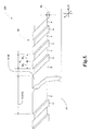
- FIGURE 5 is an isometric view showing one exemplary embodiment of a grating and reference mark structure 500 according to this invention. Components numbered similarly to those shown in FIGURES 1-4 may be similar or identical.
- the grating and reference mark structure 500 comprises a scale grating 80 and a mirror portion reference mark 50-M located on a scale member 81.
- the mirror portion reference mark 50-M is illustrated as a generic example.
- the scale grating 80 includes grating elements E extending along the direction of the Y-axis, that are separated by recessed elements G. Grating elements E are arranged periodically along the measuring axis 82, according to a grating pitch P g .
- Each of the grating elements E has a width W E along the direction of the measuring axis 82, while each of the recessed elements G has a width W G .
- the grating elements E also have a recess height H E along the direction of the Z-axis.
- the particular embodiment of the scale grating 80 shown in FIGURE 5 is designed to suppress zero order reflected light and all even diffraction orders. Methods for accomplishing this are described in the incorporated '696 patent, and are otherwise known in the art.
- the scale grating 80 may be formed as a reflective phase grating with a reflective chrome coating on both the rectangular grating elements E and the recessed elements G, and with a recess height H E between the grating elements that causes destructive interference of the zero order reflected light, for example a height of 1 ⁇ 4 of the wavelength of the source light used with the grating and reference mark structure 500.
- a 50% duty cycle that is, W E approximately equal to W G , contributes to the best suppression of the 0 th order reflected light and also suppresses the rest of the even diffraction orders.
- a mirror portion reference mark 50-M having a length LETOE along the x-axis direction, may be located within the scale grating 80.
- the scale grating 80 should remain in phase on each side of the mirror portion reference mark 50-M.
- the mirror portion reference mark 50-M is sized and located such that its boundaries are in phase with similar boundaries of the grating elements E.
- the length LETOE may coincide with (N+1/2) periods of the scale grating 80, where N is an integer.
- N may be chosen in the range of 10 to 30 periods of the scale grating 80. However, this range is exemplary only, and not limiting. Considerations related to selecting a desirable length LETOE are described in greater detail below.
- the mirror portion reference mark 50-M is illustrated as being formed to correspond to the plane of the grating elements E, but it could alternatively be formed to correspond to the plane of the grating elements G. It should be appreciated that, in various embodiments, the mirror portion reference mark 50-M may be fabricated using a subset of the same steps used to fabricate the scale grating 80. Thus, the embodiment of the reference mark 50-M shown in FIGURE 5 provides a particularly economical way of providing a reference mark that can be used in a miniature fiber optic readhead and scale arrangement that includes a phase-type scale grating 80 and an interferometric-type miniature fiber optic readhead.
- the grating and reference mark structure 500 is particularly suitable for use in the scale track 88 of the readhead and scale arrangement 1000 shown in FIGURE 1 , where the mirror portion reference mark 50-M would be located in the reference mark zone 251, and in the readhead and scale arrangements 3000 and 3000' shown in FIGURES 3 and 4 , where the mirror portion reference mark 50-M would be located in the reference mark zones 351 and 451, respectively.
- FIGURE 5 the roles of the grating and mirror features shown in FIGURE 5 and described above can be reversed to provide a grating portion reference mark, having a length LETOE, embedded in a mirror scale track portion extending along the x-axis direction, and/or in a mirror region such as that included in the end region 89 shown in FIGURE 4 .
- a grating portion reference mark, and an associated mirror scale track portion or mirror region may be fabricated using the same steps that are used to fabricate an incremental measurement scale grating along an incremental measuring scale track on a scale member 81, thus providing a particularly economical way of providing a grating-type reference mark portion that can be used in a miniature fiber optic readhead and scale arrangement that includes a phase-type incremental measurement scale grating and an interferometric-type miniature fiber optic readhead.
- Such a structure including a grating-type reference mark portion would be particularly suitable for use in the scale track 88' of the readhead and scale arrangement 2000, shown in FIGURE 2 , where the grating-type reference mark portion would be located in the reference mark zone 251', and in the readhead and scale arrangements 3000' shown in FIGURE 4 , where grating-type reference mark portion would be located in the reference mark zone 451'.
- FIGURES 6A and 6B are isometric views schematically showing various aspects of a first embodiment of a reference signal generating configuration 6000 according to this invention, in relation to an illustrated dimension relationship.
- the reference signal generating configuration 6000 comprises a reference mark readhead optical fiber arrangement 600 operably positioned relative to a generic reference mark 50A, which may comprise either a mirror reference mark portion or a grating reference mark portion (e.g., on a scale member 81, not shown), depending on whichever is appropriate in a particular readhead and scale arrangement, as previously described.
- the reference mark 50A has a dimension LETOE along the x-axis or measuring axis direction, a dimension WY along the y-axis direction and a center line RMC along the x-axis direction.
- the reference mark readhead optical fiber arrangement 600 outputs a diverging source light 650 from a central fiber, which illuminates the reference mark 50A, as illustrated by exemplary source light rays 650-1, 650-2, and 650-3.
- the source light 650 is advantageously monochromatic and spatially coherent, and may be temporally coherent in some embodiments.
- the reference mark 50A is a mirror reference mark portion surrounded by a grating track portion and/or scale track, then it will strongly reflect zero-order light back to the reference mark readhead optical fiber arrangement 600, as illustrated by the exemplary scale light rays 654-1, 654-2 and 654-3, which correspond to the source light rays 650-1, 650-2, and 650-3, respectively.
- the reference mark signal effect region 50A-SE corresponding to a mirror reference mark portion will be a region of "signal increase,” to the extent that it overlaps any fiber optic reference mark signal receiver channel aperture provided by the reference mark readhead optical fiber arrangement 600.
- the reflected zero order scale light produces a reference mark signal effect region 50A-SE proximate to the optical signal receiver apertures provided by the ends of the optical fiber arrangement 600.
- the reference mark signal effect region 50A-SE has "magnified" dimensions that are twice those of the reference mark 50A, due to the divergence of the reflected scale light. In general, due to the use of diverging source light, all reference mark signal effect regions described herein will have dimensions that are twice those of their corresponding reference marks.
- the reference mark signal effect region 50A-SE has a center line RMC-SE along the along the x-axis direction. It will be appreciated that despite the size difference between the reference mark 50A and the reference mark signal effect region 50A-SE, their centerlines RMC and RMC-SE may be aligned along the measuring axis 82, and may displace at the same rate.
- the reference mark 50A is a mirror reference mark portion (e.g., as shown in FIGURES 1 and 3 ). If the reference mark 50A is a grating reference mark portion surrounded by a mirror region or track portion (e.g., as shown in FIGURE 2 ), then the exemplary source light rays 650-1, 650-2, and 650-3 and the corresponding reflected exemplary scale light rays 654-1, 654-2 and 654-3 may be interpreted as zero-order light rays that are ordinarily provided by the surrounding mirror region or track portion (e.g., the mirror portion of the scale track 88'), but that are disrupted by the zero-order reflection suppression and higher order diffraction properties of the grating portion reference mark 50A.
- the surrounding mirror region or track portion e.g., the mirror portion of the scale track 88'
- the corresponding reference mark signal effect region 50A-SE will be a region of "signal decrease," to the extent that it overlaps any fiber optic reference mark signal receiver channel aperture provided by the reference mark readhead optical fiber arrangement 600.
- a grating portion reference mark is not limited to having grating bars aligned and spaced identically to the scale grating 80. More generally, any grating portion reference mark that diffracts a significant amount of source light away from the reference mark readhead optical fiber arrangement 600 and/or significantly suppresses zero order reflection may be used (e.g., two-dimensional gratings, etc.)
- FIGURE 6B shows a portion 6000' of the reference signal generating configuration 6000 shown in FIGURE 6A , including the reference mark readhead optical fiber arrangement 600 and the reference mark signal effect region 50A-SE.
- the reference mark readhead optical fiber arrangement 600 may comprise receiving fibers 690R1, 690R1', 690R2, and 690R2', having ends that provide reference mark signal receiver channel apertures that receive and provide the optical reference mark signals REF1, REF 1', REF2 and REF2', as shown.
- the other two fibers 690X and 690X' may be optional dummy fibers, used to facilitate a close-packing assembly technique, if desired.
- the receiving fibers 690R1, 690R1', 690R2, and 690R2' may be multi-mode fibers having an outer diameter DRF and a light carrying core area having a diameter DRA that may coincide with and/or provide a reference mark signal receiver channel aperture in some embodiments.
- a central source fiber 670 provides a light source 680, which generally emits a diverging source light, and may be provided by the end of a single-mode core of the source fiber 670, in some embodiments.
- the reference mark readhead optical fiber arrangement 600 may be configured such that all optical fibers located within a fiber optic readhead are located within a cylindrical volume having a diameter of at most 1.5 millimeters, or 1.0 millimeters, or less.
- the light carrying core diameter DRA may be approximately 200 microns, which may also be the reference mark signal receiver channel aperture diameter
- the outer diameters DRF may be approximately 250 microns
- the central fiber 670 may have the same outer diameter DRF and a single-mode core diameter of approximately 4-10 microns.
- the reference mark readhead optical fiber arrangement 600 may have an overall diameter on the order of 750 microns.
- larger or smaller fibers and/or other fiber spacings may be used.
- dashed lines AR1L, AR1R, and CAR1 show the positions of the left and right boundaries and center location, respectively, of the reference mark signal receiver channel apertures corresponding to the signals REF1 and REF1', along the x-axis direction.
- dashed lines AR2L, AR2R, and CAR2 show the positions of the left and right boundaries and center location, respectively, of the reference mark signal receiver channel apertures corresponding to the signals REF2 and REF2' along the x-axis direction.
- the dimension LCAR1CAR2 denotes the distance along the x-axis between the effective centers of the reference mark signal receiver channel apertures corresponding to signals REF1 and REF1' and the centers of the reference mark signal receiver channel apertures corresponding to signals REF2 and REF2'.
- the dimension AR12SEP denotes the separation distance between the boundaries AR1R and AR2L. More generally, as used here and in reference to FIGURES 10 and 11 , the dimension AR12SEP denotes the distance along the measuring axis direction between the interior boundaries of two reference mark signal receiver channel apertures that are included in an optical fiber arrangement, that is, between their boundaries that are closest to one another along the measuring axis direction.
- the dimension AR12SPAN denotes the total distance spanned between the boundaries AR1L and AR2R. More generally, as used here and in reference to FIGURES 10 and 11 , the dimension AR12SPAN denotes the distance spanned along the measuring axis direction between the exterior boundaries of two reference mark signal receiver channel apertures that are included in an optical fiber arrangement, that is, between their boundaries that are farthest from one another along the measuring axis direction.
- the reference mark readhead optical fiber arrangement 600 and the reference mark 50A should be configured such that such that the following relationship is fulfilled AR ⁇ 12 ⁇ SEP ⁇ 2 * LETOE ⁇ AR ⁇ 12 ⁇ SPAN and such that the resulting reference mark signals are usable to define a reference position with a desired accuracy and/or repeatability within a signal crossing region proximate to the reference mark 50A, as described in greater detail below.
- a configuration that furthermore fulfills the relationships 2 * LETOE > AR ⁇ 12 ⁇ SEP + 0.25 * AR ⁇ 12 ⁇ SPAN - AR ⁇ 12 ⁇ SEP 2 * LETOE ⁇ AR ⁇ 12 ⁇ SEP + 0.75 * AR ⁇ 12 ⁇ SPAN - AR ⁇ 12 ⁇ SEP may be advantageous (e.g., by providing a more robust and/or reliable relationship between the reference mark signals).
- a configuration that furthermore fulfills the relationships 2 * LETOE > AR ⁇ 12 ⁇ SEP + 0.4 * AR ⁇ 12 ⁇ SPAN - AR ⁇ 12 ⁇ SEP 2 * LETOE ⁇ AR ⁇ 12 ⁇ SEP + 0.6 * AR ⁇ 12 ⁇ SPAN - AR ⁇ 12 ⁇ SEP may be more advantageous.
- the dimension 2*LETOE is approximately equal to [AR12SEP + (0.5*(AR12SPAN-AR12SEP))], or approximately equal to the effective center to center distance LCAR1CAR2 between the reference mark signal receiver channel apertures corresponding to signals REF1 and REF2, to provide reference mark signals approximately as described below with reference to FIGURES 8 and 12 .
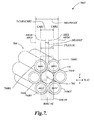
- FIGURE 7 is an isometric view of a portion 7000' of a second embodiment of a reference signal generating configuration according to this invention.
- the design and operation of the portion 7000' is in many respects similar to that of the portion 6000' of FIGURE 6B , and similarly numbered elements in the 6XX and 7XX series of numbers (e.g., the elements 690R2 and 790R2) may be similar or identical in form and operation, except as otherwise indicated below.
- the design and operation of the portion 7000' may be understood based on the previous description of the portion 6000' and the reference signal generating configuration 6000. Therefore, only the significant differences between the operation of the portions 6000' and 7000' are described below.
- the primary difference between the reference mark readhead optical fiber arrangements 700 and 600 is that the optical fiber arrangement 700 has a different rotational orientation in the XY plane, allowing the ends of fibers which are adjacent to one another along the x-axis direction to provide the reference mark signal receiver channel apertures that receive and provide the optical signals REF1, REF 1', REF2 and REF2' (corresponding to the fibers 790R1, 790R1', 790R2, and 790R2', respectively).
- a reference signal generating configuration corresponding to the portion 7000' may generally be configured according to the dimensional considerations and signal considerations outlined above with reference to EQUATIONS 1-5.
- the dimension 2*LETOE is approximately equal to [AR12SEP + (0.5*(AR12SPAN-AR12SEP))], or approximately equal to the effective center to center distance LCAR1CAR2 between the reference mark signal receiver channel apertures corresponding to signals REF1 and REF2, to provide reference mark signals approximately as described below with reference to FIGURE 8 .
- the dimension 2*LETOE of the reference mark signal effect region 50B-SE and corresponding dimension LETOE of the corresponding reference mark are selected to be less than for the reference signal generating configuration corresponding to the portion 7000'.
- either the reference signal generating configuration 6000, or a reference signal generating configuration corresponding to the portion 7000' is suitable for use in the readhead 200 and scale track 88 of the readhead and scale arrangement 1000 shown in FIGURE 1 , where a mirror portion reference mark would be located in the reference mark zone 251.
- either configuration is also suitable for use in the readhead 200 and scale track 88' of the readhead the readhead and scale arrangement 2000 shown in FIGURE 2 , where a grating portion reference mark would be located in the reference mark zone 251'.
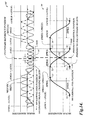
- FIGURE 8 is a diagram showing two schematic signal charts 60 and 70, which respectively correspond to the reference signal generating configuration 6000 of FIGURES 6A and 6B , and a reference signal generating configuration corresponding to the portion 7000', shown in FIGURE 7 .
- the signal chart 60 corresponding to the reference signal generating configuration 6000 of FIGURES 6A and 6B , shows two reference signals, a combined signal (REF1+REF1') and a combined signal (REF2+REF2), as a function of relative position along the measuring axis 82 between the reference mark signal effect region 50A-SE (or the reference mark 50A), and the reference mark readhead optical fiber arrangement 600.
- the point 61 corresponds to a position where the center line RMC of the reference mark 50A coincides with a position displaced by the length LETOE to the left of the position AR1L, shown in FIGURE 6B .
- the reference mark signal effect region 50A-SE does not overlap any reference mark signal receiver channel apertures and no significant signal is produced at the point 61.
- the reference mark signal effect region 50A-SE increasingly overlaps the REF1 and REF1' reference mark signal receiver channel apertures until a maximum is reached at a point 62, after a displacement equal to the reference mark signal receiver channel aperture diameter (e.g., the light carrying core diameter DRA).
- the reference mark 50A continues to displace to the right, no further signal change is observed until the points 63 and 63', which mark the left limit of a signal crossing region where the (REF1+REF1') signal and the (REF2+REF2') signal converge (or diverge) to (or from) a common value.
- the signal (REF1+REF1') begins to decrease as the overlap between the reference mark signal effect region 50A-SE and the REF1 and REF1' reference mark signal receiver channel apertures decreases.
- the reference mark signal receiver channel apertures have similar dimensions and the length LETOE of the reference mark 50A is selected such that the dimension 2*LETOE of the reference mark signal effect region 50A-SE is approximately equivalent to the dimension LCAR1CAR2 shown in shown in FIGURE 6B , the signal (REF2+REF2') simultaneously begins to increase at the point 63', as the overlap between the reference mark signal effect region 50A-SE and the REF2 and REF2' reference mark signal receiver channel apertures increases.
- the center line RMC of the reference mark 50A is symmetrically located between the REF1/REF1' reference mark signal receiver channel apertures and the REF2/REF2' reference mark signal receiver channel apertures (at the position shown in FIGURE 6B ) and the signals (REF1+REF1') and (REF2+REF2') are therefore nominally equal.
- the behavior of the signals (REF1+REF1') and (REF2+REF2') at the remaining points 65, 65', 66 and 67 may be understood by analogy with the previous explanation.
- the points 65 and 65' analogous to the points 63 and 63', mark the right limit of the signal crossing region.
- the signal chart 70 corresponding to a reference signal generating configuration that includes and corresponds to the portion 7000' shown in FIGURE 7 , is analogous to the signal chart 60, described above. That is, the point 71 is analogous to the point 61, and so on.
- the behavior of the signals (REF1+REF1') and (REF2+REF2') at the points 71-77 may be understood by analogy with the previous explanation, in combination with the description of FIGURE 7 .
- the signal (REF1+REF1') begins to decrease as the overlap between the reference mark signal effect region 50B-SE and the REF1 and REF1' reference mark signal receiver channel apertures decreases.
- the reference mark signal receiver channel apertures have similar dimensions and the length LETOE of the reference mark 50B is selected such that the dimension 2*LETOE of the reference mark signal effect region 50B-SE is approximately equivalent to the dimension LCAR1CAR2 shown in shown in FIGURE 7 , the signal (REF2+REF2') simultaneously begins to increase at the point 73', as the overlap between the reference mark signal effect region 50b-SE and the REF2 and REF2' reference mark signal receiver channel apertures increases.
- the center line RMC of the reference mark 50B is symmetrically located between the REF1/REF1' reference mark signal receiver channel apertures and the REF2/REF2' reference mark signal receiver channel apertures (at the position shown in FIGURE 7 ) and the signals (REF1+REF1') and (REF2+REF2') are therefore nominally equal.
- the features of the signals (REF1+REF1') and (REF2+REF2') of the signal chart 70 are spaced more closely along the measuring axis than those of the signal chart 60, because the reference mark length LETOE is shorter in the reference signal generating configuration corresponding to the signal chart 70, and the center-to-center spacing between the REF1/REF1' reference mark signal receiver channel apertures and the REF2/REF2' reference mark signal receiver channel apertures is also less.
- a reference position detection circuit may identify the position where the individual signals (REF1+REF1') and (REF2+REF2') cross and are equal as the reference position.
- selecting the edge-to-edge length LETOE according to the dimensional considerations and signal considerations outlined above in relation to EQUATIONS 1-5 generally provides a reference signal generating configuration that provides reference mark signals that are adequate to define a reference position (e.g., where two respective reference signals have equal values) within a signal crossing region proximate to a reference mark. Fulfilling the relationships of EQUATIONS 2 and 3, or 4 and 5, may provide a particularly reliable and/or robust relationship between the reference mark signals in the signal crossing region.
- the reference signal generating configurations corresponding to the signal charts 60 and 70 each fulfill these relationships, and thereby insure a robust signal crossing region that includes signals that nominally cross at a signal value approximately halfway between their maximum and minimum values, as shown in FIGURE 8 .
- the signal polarities shown in FIGURE 8 may generally correspond to those produce by a mirror portion reference mark surrounded by a grating region. All signals would generally be inverted for a grating portion reference mark surrounded by a mirror region. In practice, all the signals will generally include common mode DC offsets, which are not shown in FIGURE 8 .
- reference signal generating configurations such as those disclosed above and further below, designed in accordance with the dimensional considerations and signal considerations outlined above with reference to EQUATIONS 1-5, can provide a plurality of respective reference mark signals that define a reference position that is repeatable to within less than one-half period of desirable spatially periodic incremental measurement signals within the signal crossing region proximate to a reference mark, such that the reference mark can reliably indicate a particular period or cycle of the incremental measuring signals and the associated particular wavelength along the scale.
- repeatability within less than 4, or 2 is readily achieved, and submicron repeatability may be achieved, especially when the relationships of EQUATIONS 2 and 3, or 4 and 5, are fulfilled.
- FIGURES 9 and 10 are isometric views schematically showing various aspects of the operation of an integrated reference signal and incremental signal generating configuration 8000 (also referred to as the integrated signal generating configuration 8000) according to this invention, including a third embodiment of a reference signal generating configuration according to this invention.
- the view shown in FIGURE 9 does not show a phase mask element 861, which is an essential element of the integrated signal generating configuration 8000, in order to more clearly illustrate other aspects of its operation.
- the phase mask element 861 is described below with reference to FIGURE 10 .
- FIGURE 9 shows certain elements of the integrated signal generating configuration 8000, including an integrated readhead optical fiber arrangement 800 (less the phase mask element 861, shown in FIGURE 10 ) operably positioned relative to a generic mirror portion reference mark 50C surrounded by the scale grating 80 (e.g., on a scale member 81, not shown).
- the reference mark 50C has a dimension LETOE along the x-axis direction, and a centerline RMC, as shown.
- the integrated readhead optical fiber arrangement 800 outputs a diverging source light 850 from a light source 880 provided by a central fiber, which illuminates the reference mark 50C and the surrounding scale grating 80 at the illumination spot 853.
- the source light 850 is advantageously monochromatic and spatially coherent, and may be temporally coherent in some embodiments.
- the scale grating 80 provides reflectively diffracted +/- first order scale light 855A and 855B, represented by its central rays in FIGURE 9 .
- the +/- first-order scale lights 855A and 855B illuminate regions 855A' and 855B', respectively, which overlap in an interference zone 856 to form interference fringes 866 proximate to a receiver plane 860 of the integrated readhead optical fiber arrangement 800.
- the interference fringes are spatially filtered by the phase mask element 861 (shown in FIGURE 10 ) over the ends of the optical fibers that receive the optical quadrature signals A, A-, B and B-, according to previously described principles, and as described in greater detail below with reference to FIGURE 10 .
- the mirror portion reference mark 50C falls within the illumination spot 853, it reflects the diverging coherent source light 850 to provide the reference mark signal effect region 50C-SE, which has dimensions that are twice those of the mirror portion reference mark 50C and a centerline RMC-SE that is aligned with the centerline RMC, according to principles previously outlined with reference to FIGURE 6A . Additional details regarding the operation of the integrated reference signal and incremental signal generating configuration 8000 are described below with reference to FIGURE 10 .
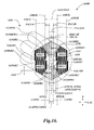
- FIGURE 10 shows a portion 8000' of the integrated signal generating configuration 8000 shown in FIGURE 9 , including the integrated readhead optical fiber arrangement 800, the reference mark signal effect region 50C-SE, and a phase mask element 861.
- FIGURE 10 does not show the interference fringes 866 in the interference zone 856, but it should be understood that such fringes are present during operation, as previously described.
- the integrated readhead optical fiber arrangement 800 may comprise a central source fiber 870 that provides the light source 880, which may be provided by the end of a single-mode core of the source fiber 870 in some embodiments, and receiver fibers 890A, 890A', 890B, 890B', 890R1, and 890R2, that provide receiver channels that receive the optical signals A, -A, B, -B, REF1, and REF2, respectively, as shown.
- the integrated readhead optical fiber arrangement 800 also includes a phase mask element 861 comprising phase masks 820A, 820B, 820A', 820B', blocking masks 820BR1 and 820BR2, and open aperture masks 820R1 and 820R2.
- Dashed lines AR1L, AR1R and CAR1 show the positions of the left and right boundaries and effective center location, respectively, of the reference mark signal receiver channel aperture corresponding to the signal REF1
- dashed lines AR2L, AR2R and CAR2 show the positions of the left and right boundaries and effective center location, respectively, of the reference mark signal receiver channel aperture corresponding to the signal REF2.
- the dimension LCAR1CAR2 denotes the distance along the x-axis between the effective centers of the reference mark signal receiver channel apertures corresponding to signals REF1 and REF2.
- the dimension AR12SPAN denotes the total distance spanned between the boundaries AR1L and AR2R.
- the dimension AR12SEP denotes the distance along the measuring axis direction between the interior boundaries of two reference mark signal receiver channel apertures that are included in an optical fiber arrangement, that is, between their boundaries that are closest to one another along the measuring axis direction.
- the dimension AR12SEP is between the boundaries AR1R and AR2L and is zero, so it is not labeled in FIGURE 10 , in order to avoid confusion.
- the light receiving area of previously described reference mark signal receiver channel apertures has been defined solely by the light carrying core area at the end of their respective reference mark signal receiver channel optical fibers
- the light receiving area of the reference mark signal receiver channel apertures 890R1 and 890R2 is defined partially by the boundary of the light carrying core area at the end of their respective receiver channel optical fibers and partially by their respective blocking/open aperture masks 820BR1/820R1 and 820BR2/820R2.
- analogous aperture masks could completely circumscribe and define the light receiving area of reference mark signal receiver channel apertures, if desired.
- the respective blocking/open aperture masks 820BR1/820R1 and 820BR2/820R2 include no structure that is spatially periodic along the measuring axis direction, so that any interference fringe light received by the reference mark signal receiver channel apertures 890R1 and 890R2 will not create a significant spatially periodic signal component that disturbs the desired reference mark signals.
- the phase masks 820A, 820B, 820A', and 820B' are located at the receiving plane 860, and spatially filter the interference fringes in the interference zone 856 to provide quadrature-type periodic incremental measurement signals A, A', B, and B', respectively.
- the phase masks 820A, 820B, 820A', and 820B' have relative spatial phases of 0, 90, 180 and 270 degrees, respectively. It will be appreciated that the relative positions of the measurement signals A, A', B, and B', are illustrative only, and not limiting.
- the phase masks may be configured to provide any desired arrangement for the measurement signals A, A', B, and B'.
- Various operation and design principles that are relevant to the phase mask element 861, as well as alternative spatial phase arrangements, are described in the incorporated references.
- Blocking masks 820BR1 and 820BR2 and open aperture masks 820R1 and 820R2 are located at the receiving plane 860 to mask the ends of fibers 890R1 and 890R2 and provide reference signals REF1 and REF2. It will be appreciated that in the absence of the blocking masks 820BR1 and 820BR2 the ends of the receiver fibers 890R1 and 890R2, which are collocated along the direction of the measuring axis 82, would respond to various positions of the reference mark signal effect region 50C-SE with identical signals.
- the arrangement of the masks 820BR1, 820BR2, 820R1 and 820R2 provides reference mark signal receiver channel apertures that are offset along the direction of the measuring axis 82, to provide reference signals REF1 and REF2 that exhibit a desirable signal crossing region, as described further below with reference to FIGURE 12 .
- the fringes arising from the scale grating 80 are present continuously during the operation of the integrated signal generating configuration 8000, in order to continuously generate these quadrature signals, as outlined above.
- the fringes may be weakened when the mirror portion reference mark 50C is present in the illumination spot 853, detracting from the amount of diffracted +/- first order scale light 855A and 855B.
- the phase masks 820A, 820B, 820A', and 820B' will admit a portion of the zero order reflected light included in the reference mark signal effect region 50C-SE, when it overlaps their locations.
- the amplitudes and offsets of the quadrature signals A, A', B, and B' will generally be affected by the reference mark 50C, which may detract from the resulting incremental displacement measurement accuracy. Therefore, in some embodiments, signal processing (e.g., adaptive amplitude "gain control" and/or DC offset compensation and/or phase compensation, or the like) may be applied to the quadrature signals A, A', B, and B' to at least partially negate such effects, and/or the length LETOE and/or area of the reference mark 50C may be limited to limit its disruptive effects.
- signal processing e.g., adaptive amplitude "gain control" and/or DC offset compensation and/or phase compensation, or the like
- the length LETOE and/or area of the reference mark 50C may be limited to limit its disruptive effects.
- the fringes arising from the scale grating 80 are present continuously during the operation of the integrated signal generating configuration 8000.
- the open aperture masks 820R1 and 820R2 provide no spatial filtering over the ends of receiver fibers 890R1, and 890R2, and the light from a plurality of fringes simply provides a relatively constant average amount of light to the reference signals REF1 and REF2, independent of displacement.
- the reference mark signal effect region 50C-SE overlaps the locations of the open aperture masks 820R1 and 820R2, its zero order reflected light significantly increases the reference signals REF1 and REF2, as a function of the amount of overlap.
- the fibers 890 may have light carrying core areas having diameters DRA of approximately 200 microns, outer diameters DRF of approximately 250 microns and the central fiber 870 may have the same outer diameter DRF, and a single-mode core diameter, or mode-field diameter, of approximately 4-10 microns.
- the reference mark readhead optical fiber arrangement 800 may have an overall diameter on the order of 750 microns.
- larger or smaller fibers and/or other fiber spacings may be used.
- the scale grating 80 may have a grating pitch P g of approximately 4 microns, and the fringes 866 may have a similar pitch.
- the reference mark signal receiver channel apertures defined by the reference mark signal receiver fiber ends and the blocking/open aperture masks 820BR1/820R1 and 820BR2820R2 may have a dimension on the order of 100 microns along the direction of the measuring axis 82.
- the reference mark 50C may have a length LETOE that is advantageously of approximately 38 microns in one embodiment, which provides a desirable tradeoff between adequate reference mark signal strength and minimal disturbance to the incremental measurement signals.
- LETOE the dimensional relationships outlined above for LETOE are exemplary only, and not limiting. In various applications, additional design considerations may favor smaller or larger dimensions for LETOE.
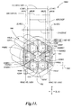
- FIGURE 11 is an isometric view showing a portion 9000' of a second integrated signal generating configuration according to this invention, including a fourth embodiment of a reference signal generating configuration according to this invention.
- the design and operation of the portion 9000' is in many respects similar to that of the portion 8000' of FIGURE 10 , and similarly numbered elements in the 8XX and 9XX series of numbers (e.g., the elements 820R2 and 920R2) may be similar or identical in form and operation, except as otherwise indicated below.
- the design and operation of the portion 9000' may be understood based on the previous description of the portion 8000' and the integrated signal generating configuration 8000. Therefore, only the significant differences between the operation of the portions 8000' and 9000' are described below.
- FIGURE 11 shows the portion 9000' including the integrated readhead optical fiber arrangement 900, the reference mark signal effect region 50D-SE, and a phase mask element 961.
- the primary difference between the portions 8000' and 9000' is that the optical fiber arrangements 800 and 900 have a different rotational orientation in the XY plane.
- receiver fibers 990R1 and 990R2 which are separated along the x-axis direction, provide the reference signals REF1 and REF2.
- the reference mark signal effect region 50D-SE includes two signal effect sub-regions 50D1-SE and 50D2-SE, having individual dimensions 2LSEG, and providing an interior edge-to-edge dimension 2*LETOE.
- a corresponding mirror portion reference mark (not shown) including two mirror sub-portions or reference mark portions designated 50D1 and 50D2 having individual dimensions LSEG, and providing an interior edge-to-edge dimension LETOE, provides the two separated signal effect sub-regions or reference mark portions 50D1-SE and 50D2-SE according to previously outlined principles.
- the dimension 2*LETOE corresponds to the distance between the interior boundaries of the two signal effect sub-regions 50D1-SE and 50D2-SE
- the relationship between the sub-regions 50D1-SE and 50D2-SE may be such that the distance between their exterior boundaries (rather than their interior boundaries) corresponds to the same dimension 2*LETOE.
- a total area of the reference mark is advantageously limited in comparison to a single portion reference mark of similar overall length and its disruptive effects on periodic incremental measurement signals are therefore advantageously limited.
- each of the two reference mark portions may have a dimension along the measuring axis direction which is at least 0.25*(AR12SPAN-AR12SEP) and at most 0.75*(AR12SPAN-AR12SEP). In various other embodiments, each of the two reference mark portions may have a dimension along the measuring axis direction which is at least 0.4*(AR12SPAN-AR12SEP) and at most 0.6*(AR12SPAN-AR12SEP).
- selecting the edge-to-edge length LETOE according to the dimensional considerations and signal considerations outlined above in relation to EQUATIONS 1-5 generally provides a robust reference signal generating configuration, especially when the relationships of EQUATIONS 2 and 3, or 4 and 5, are fulfilled.
- the reference signals REF1 and REF2 provided by the integrated signal generating configuration corresponding to the portion 9000' exhibit a desirable signal relationship in a signal crossing region, as described further below with reference to FIGURE 12 .
- either the reference signal generating configuration 8000, or a reference signal generating configuration corresponding to the portion 9000' is suitable for use in the readhead 300 of the readhead the readhead and scale arrangements 3000 and 3000' shown in FIGURES 3 and 4 .
- FIGURE 12 is a diagram showing two schematic signal charts 810 and 910, which respectively correspond to the integrated signal generating configuration 8000 shown in of FIGURES 9 and 10 , and an integrated signal generating configuration corresponding to the portion 9000' shown in FIGURE 11 .
- the signal charts 810 and 910 do not have the same vertical or horizontal scaling and, in practice, all the signals will generally include common mode DC offsets, which are not shown in FIGURE 12 .
- the signal chart 810 corresponding to the reference signal generating configuration 8000 of FIGURES 9 and 10 , shows two reference signals, a signal REF1 and a signal REF2 as a function of relative position along the measuring axis 82 between the reference mark signal effect region 50C-SE (or the reference mark 50C), and the reference mark readhead optical fiber arrangement 800.
- the point 811 corresponds to a position where the center line RMC-SE of the reference mark 50C coincides with a position displaced by the length LETOE of the reference mark 50C to the left of the position AR1L shown in FIGURE 10 . Accordingly, the reference mark signal effect region 50C-SE does not overlap the REF1 reference mark signal receiver channel aperture, and no significant signal is produced at the point 811.
- the reference mark signal effect region 50C-SE increasingly overlaps the REF1 reference mark signal receiver channel aperture until a maximum is reached at a point 812, at a position where the centerline RMC-SE is a distance LETOE to the left of the position AR1R shown in FIGURE 10 .
- the signal REF1 begins to decrease as the overlap between the reference mark signal effect region 50C-SE and the REF1 reference mark signal receiver channel aperture decreases.
- the signal REF2 simultaneously begins to increase at the point 812', as the overlap between the reference mark signal effect region 50C-SE and the REF2 reference mark signal receiver channel aperture increases.
- the center line RMC-SE of the reference mark 50C is symmetrically located along the REF1 reference mark signal receiver channel aperture and the REF2 reference mark signal receiver channel aperture (at the position shown in FIGURE 10 ) and the signals REF1 and REF2 are therefore nominally equal. Because the reference mark signal receiver channel apertures have similar dimensions and the length LETOE of the reference mark 50C is selected such that the dimension 2*LETOE of the reference mark signal effect region 50C-SE is approximately equivalent to the dimension LCAR1CAR2 shown in shown in FIGURE 10 , the signals REF1 and REF2 cross at a value that is approximately midway between their maximum and minimum values in the signal crossing region, which leaves a robust margin for individual signal variations that may arise from various causes. The behavior of the signals REF1 and REF2 at the remaining points 814, 814' and 815 may be understood by analogy with the previous explanation.
- the signal chart 910 corresponds to a reference signal generating configuration that includes and corresponds to the portion 9000' shown in FIGURE 11 .
- the signal chart 810 shows two reference signals, a signal REF1 and a signal REF2 as a function of relative position along the measuring axis 82 between the centerline RMC-SE-50D2 of the reference mark signal effect sub-region 50D2-SE and the optical fiber arrangement 900.
- the centerline RMC-SE-50D2 coincides with centerline of a corresponding reference mark sub-portion, hereby designated as sub-portion 50D2 of a two-portion reference mark 50D, which also includes a sub-portion designated 50D1.
- the point 911 corresponds to a position where the center line RMC-SE-50D2 coincides with a position displaced by the length LSEG to the left of the position AR2L shown in FIGURE 11 . Accordingly, the reference mark signal effect region 50D2-SE does not overlap with the REF2 reference mark signal receiver channel aperture, and no significant signal is produced at the point 811. As the reference mark 50D is displaced to the right, the reference mark signal effect region 50D2-SE increasingly overlaps the REF2 reference mark signal receiver channel aperture until a maximum is reached at a point 912, where the centerline RMC-SE-50D2 is a distance LSEG to the left of the position AR2R shown in FIGURE 11 .
- the signal REF2 begins to decrease as the overlap between the reference mark signal effect region 50D2-SE and the REF2 reference mark signal receiver channel aperture decreases and the signal REF1 simultaneously begins to increase at the point 912', as the overlap between the reference mark signal effect region 50D1-SE and the REF1 reference mark signal receiver channel aperture increases.
- the reference mark 50D is symmetrically located between the REF1 and REF2 reference mark signal receiver channel apertures (at the position shown in FIGURE 11 ) and the signals REF1 and REF2 are therefore nominally equal.
- the reference mark signal receiver channel apertures have similar dimensions and the length LETOE of the reference mark 50D is selected such that the dimension 2*LETOE of the reference mark signal effect region 50D-SE is approximately equivalent to the dimension LCAR1CAR2 shown in shown in FIGURE 11 , the signals REF1 and REF2 cross at a value that is approximately midway between their maximum and minimum values in the signal crossing region, which leaves a robust margin for individual signal variations that may arise from various causes.
- the behavior of the signals REF1 and REF2 at the remaining points 914, 914' and 915 may be understood by analogy with the previous explanation.
- the points 916-918 illustrate a secondary REF2 signal that is provided by the sub-region 50D1-SE overlapping the REF2 receiver, as the reference mark 50D continues to displace to the right.
- the secondary REF2 signal corresponding to the points 916-918 is irrelevant, as is the analogous secondary REF1 signal, except for their potential use as indicators that the reference position is approaching, or a confirmation that the reference position should have been detected and is receding, depending on the displacement direction.
- the reference mark signal generating configurations outlined above generally provide a single reference mark signal having a first level of resolution and repeatability.
- the first level of resolution and repeatability may be on the order of 0.2 microns.
- the term "reference mark primary signal" may be used to refer to reference mark signals generated as outlined above.
- reference mark secondary signals may be used to refer to such reference mark signals that offer an improved level of resolution and repeatability.
- the reference signal generating configurations outlined below provide such reference mark secondary signals.
- the embodiments outlined below with reference to FIGURES 13-18 are generally designed in accordance with EQUATION 1 (and/or EQUATION 2, 3, 4 or 5) and use principles outlined above with reference to FIGURES 1-12 to generate reference mark primary signals, in combination with additional features outlined below, which generate reference mark secondary signals.
- the reference mark secondary signals indicate a reference mark position with higher resolution and repeatability than the reference mark primary signals (e.g., resolution and/or repeatability approximately ten times better, which may be on the order of 20 nanometers).
- the reference mark secondary signals are periodic. Therefore, a primary reference mark position or primary signal crossing point derived from the reference mark primary signals is used to eliminate any potential secondary reference mark position ambiguity associated with that periodicity, as described in greater detail below.
- the reference mark may comprise either a mirror-like reference mark portion located on a scale track that includes a grating (e.g., see reference scale track 88 in FIGURE 1 ), or, alternatively, a grating type reference mark portion located on a mirror-like reference scale track (e.g., see reference scale track 88' in FIGURE 2 ).
- the reference mark cannot comprise a grating type reference mark portion surrounded by a mirror-like track portion, for reasons described below.
- an element numbered 16 20BPR2 may be analogous to an element numbered 8 208R2, based on the similar numerical suffix "20BR2" as modified with the inclusion of "P" for "primary”.
- an element numbered 13 90PR1 may be analogous to the element number 7 90R1, etc.
- an "S" may be inserted into a suffix used for an analogous element.
- a receiver fiber numbered 15 90SR1 may be analogous to a receiver fiber numbered 8 90R1, based on the similar numerical suffix " 9 0R1 " as modified with the inclusion of "S" for "secondary".
- FIGURE 13 is an isometric view schematically showing various aspects of the operation of a portion of a fifth embodiment of a reference signal generating configuration 13000 according to this invention.
- the reference signal generating configuration 13000 generates reference mark primary signals according to principles previously outlined with reference to FIGURE 7 , and elements numbered with analogous numbers in FIGURES 13 and 7 , may be similar or identical in form and operation, except as otherwise indicated below.
- FIGURE 13 shows various elements of the reference signal generating configuration 13000, including a reference mark readhead optical fiber arrangement 1300, the reference mark primary signal effect region 50E-SE, and a mask element 1361.
- the reference mark readhead optical fiber arrangement 1300 may comprise receiving fibers 1390PR1, 1390PR1', 1390PR2, 1390PR2', which receive and provide reference mark primary signals PREF1, PREF1', PREF2, PREF2', and receiving fibers 1390SR1 and 1390SR2, which receive and provide reference mark secondary signals SREF1 and SREF2 as described further below.
- the reference mark primary signal effect region 50E-SE may be analogous or identical to the reference mark signal effect region 50B-SE shown in FIGURE 7 .
- the receiving fibers 1390PR1, 1390PR1', 1390PR2, 1390PR2' may be analogous or identical to the receiving fibers 790PR1, 790PR1', 790PR2, and 790PR2' shown in FIGURE 7 . The operation of these elements and the resulting signals may therefore be understood according to previously described principles.
- the reference mark secondary signal receiver channels comprising the receiving fibers 1390SR1 and 1390SR2 which carry the reference mark secondary signals SREF1 and SREF2, will now be outlined.
- the grating track portion may provide reflectively diffracted +/- first order scale lights, which illuminate regions which overlap to form interference fringes in an interference zone proximate to a receiver plane of the mask element 1361.
- FIGURE 13 shows such an interference zone 1356-SSE, also referred to as the reference mark secondary signal effect region 1356-SSE.
- interference fringes are locally disrupted or dominated by zero order reflected light in the vicinity of the reference mark primary signal effect region 50E-SE, in order to provide the reference mark primary signals PREF1, PREF1', PREF2, PREF2' according to previously described principles.
- the spatial filter masks 1320SR1 and 1320SR2 at the receiving plane of the mask element 1361, mask the receiver channel apertures provided by the ends of the receiving fibers 1390SR1 and 1390SR2, and spatially filter the interference fringes in the reference mark secondary signal effect region 1356-SSE to provide the spatially periodic signals SREF1 and SREF2, respectively.
- the spatial filter masks 1320SR1 and 1320SR2 have light-blocking elements arranged at a pitch that is the same as the interference fringes, and are arranged relative to one another with a nominal spatial phase difference of 180 degrees, to provide signals SREF1 and SREF2 as described in greater detail below with reference to FIGURE 14 . It will be appreciated that the light blocking element pitch shown in FIGURE 13 , and following figures, is not necessarily to scale and may be exaggerated for purposes of illustration.
- reference mark primary signals e.g., PREF1, PREF1', PREF2, PREF2'
- design considerations analogous to those previously outlined with reference to FIGURES 6-11 may be applied (e.g., by treating APR12SEP and APR12SPAN similarly to AR12SEP and AR12SPAN, etc.)
- reference mark secondary signals e.g., SREF1, SREF2
- additional design relationships are desirable between the dimensions and/or locations of the reference mark primary signal effect region (e.g., the region 50E-SE) and the reference mark secondary signal receiver channel apertures (e.g., as provided by the ends of the receiving fibers 1390SR1 and 1390SR2).
- FIGURE 13 also shows dashed lines ASR1L and ASR1R, and ASR2L and ASR2R, marking the left and right boundaries, along the x-axis direction, of exemplary reference mark secondary signal receiver channel apertures provided by the receiving fibers 1390SR1 and 1390SR2.
- a separation distance ASR12SEP is shown between ASR1R and ASR2L.
- a reference signal generating configuration e.g., the reference signal generating configuration 13000
- This relationship corresponds to a configuration wherein the reference mark primary signal effect region 50E-SE may be positioned between the receiver channel apertures provided by the receiving fibers 1390SR1 and 1390SR2, such that they derive desirable signals from the interference fringe light, without being significantly affected by the zero order reflected light of the primary signal effect region 50E-SE.
- the reference mark primary signal effect region 50E-SE may be centered relative to the receiver channel apertures provided by the receiving fibers 1390PR1, 1390PR1', 1390PR2, and 1390PR2' in order to generate desirable reference mark primary signals (e.g., REF1, PREF1', PREF2, PREF2') in a desirable primary signal crossing region, all approximately as shown in FIGURE 13 , and as described in greater detail below with reference to FIGURE 14 .
- a clearance dimension PSCLR may be provided as shown in FIGURE 13 .
- PSCLR is the clearance from the edge of the reference mark primary signal effect region 50E-SE to the boundaries of reference mark signal secondary receiver channel apertures when the reference mark primary signal effect region 50E-SE is nominally centered between those boundaries along the measuring axis 82.
- PSCLR In various embodiments it is desirable for PSCLR to be greater that zero, or more desirably at least 10 microns, and in some embodiments at least 25, and in other embodiments at least 50 microns.
- FIGURE 14 is a diagram including a signal chart 70' schematically showing reference mark primary signals, and a signal chart 60' schematically showing reference mark secondary signals, all generated according to this invention.
- signal amplitudes, spatial periods, etc. may vary from those shown in FIGURE 14 , which is illustrative only, and not limiting.
- the signals are described corresponding to the reference signal generating configuration 13000 of FIGURE 13 .
- FIGURE 14 shows a signal chart 70' illustrating the combined reference mark primary signals (PREF1 + PREF1') and (PREF2+ PREF2').
- Signal chart 70' is analogous to signal chart 70 of FIGURE 8 , with analogous dimension names adapted to correspond to the description of FIGURE 13 .
- Signal chart 70' may therefore be understood according to previously described principles, with the difference that the primary reference position indicated by the signal crossover point 74' is regarded merely as a primary or first indicator of the reference position. As illustrated by the dashed line extending from the signal crossover point 74' to the signal chart 60', the signal crossover point 74' and/or the primary reference position has a specific fixed spatial relationship to the reference mark secondary signals SREF1 and SREF2 shown in the signal chart 60'.
- the reference mark secondary signals SREF1 and SREF2 are spatially periodic with a period corresponding to the fringe pitch, and are 180 degrees out of phase with one another, due to the arrangement of the spatial filter masks 1320SR1 and 1320SR2.
- the signal chart 60' also shows that when the reference mark primary signal effect region 50E-SE crosses a receiver channel aperture corresponding to a reference mark secondary signal, it may generally contribute a DC signal component (e.g., the DC signal component SREF1DC or SREF2DC), that adds to the spatially periodic signal component corresponding to that receiver channel aperture.
- the reference mark secondary signals SREF1 and SREF2 need not include a significant DC signal component, which is advantageous for reliably determining the high resolution secondary reference position.
- a particular secondary signal crossing region of the reference mark secondary signals SREF1 and SREF2 is significantly narrower than the primary signal crossing region.
- the signal relationships in FIGURE 14 are shown schematically, for clarity of illustration.
- the secondary signal crossing region may be on the order of 10 times narrower than the secondary signal crossing region.
- the position of a particular signal crossing point 64'of the secondary signals SREF1 and SREF2, and the corresponding secondary reference position may be determined with spatial resolution and/or accuracy that is better (e.g., about 10 times better) than the primary signal crossing point 74' and/or primary reference position.
- the particular signal crossing point 64' may generally be indistinguishable from the other periodic signal crossing points that occur in its vicinity.
- the primary signal crossing point 74' has a specific fixed spatial relationship to the reference mark secondary signals SREF1 and SREF2 shown in the signal chart 60', and has a resolution and accuracy that is better +/- half a period of the secondary signals SREF1 and SREF2. Therefore, the primary signal crossing point 74' may be used to reliably indicate or identify the particular secondary signal crossing point 64'.
- a high resolution secondary reference position may be repeatedly and reliably determined according to this invention, based on a particular secondary signal crossing point 64'.
- One exemplary signal processing method for determining the high resolution secondary reference position is outlined below with reference to FIGURE 19 .
- FIGURE 15 is an isometric view schematically showing various aspects of the operation of a portion of a sixth embodiment of a reference signal generating configuration 15000 according to this invention.
- the reference signal generating configuration 15000 generates reference mark signals according to principles previously outlined with reference to FIGURE 13 , and may be understood by analogy with previous description. Therefore, only significant differences are described below. Elements numbered with analogous numbers in FIGURES 15 and 13 may be similar or identical in form and operation, except as otherwise indicated below.
- the primary differences in the reference signal generating configuration 15000 are that the dimension 2*LETOE of the reference mark primary signal effect region 50F-SE is significantly narrower than that of the primary signal effect region 50E-SE shown in FIGURE 13 , and that the receiver channel apertures associated with the reference mark primary signals PREF1, PREF1', PREF2, and PREF2' are defined by the mask element 1561.
- the mask element 1561 includes blocking mask portions 1520BPR1, 1520BPR1', 1520BPR2 and 1520BPR2' and open aperture mask portions 1520PR1, 1520PR1', 1520PR2 and 1520PR2', which are positioned over the receiving fibers 1590PR1, 1590PR1', 1590PR2 and 1590PR2', respectively.
- This arrangement provides circular (or other shapes, in various embodiments) receiver channel apertures that have dimensions and positions that are designed to complement a desired dimension 2*LETOE of the reference mark primary signal effect region 50F-SE, according to previously described principles.
- the reference signal generating configuration 15000 may provide a larger clearance dimension PSCLR, which is advantageous for reasons outlined previously.
- the open aperture mask portions 1520PR1, 1520PR1', 1520PR2 and 1520PR2' may be configured with a relative small dimension along the measuring axis 82, to provide a steeper reference mark primary signal change in a narrower primary signal crossover region. In some embodiments, this may enhance the resolution and/or accuracy of the primary signal crossing point 74', which may help in reliably identifying a particular secondary signal crossover region and/or signal crossover point. This may be particularly useful when the spatial period of the reference mark secondary signals is small (e.g., on the order of 4 microns). Otherwise, the design and operation of the reference signal generating configuration 15000 may be understood based the analogous design and operation previously described with reference to FIGURE 13 , and elsewhere herein.
- FIGURE 16 is an isometric view schematically showing various aspects of the operation of a portion of a seventh embodiment of a reference signal generating configuration 16000 according to this invention. It may be seen that in comparison to the embodiments shown in FIGURES 13 and 15 , that the optical fiber arrangement 1600 shown in FIGURE 16 has a different rotational orientation in the XY plane. This allows the reference mark primary signal effect region 50F-SE to be positioned between the ends of four fibers, rather than two, to provide reference mark secondary signal receiver channel apertures that receive and provide four secondary signals SREF1, SREF 1', SREF2 and SREF2' (corresponding to the fibers 1690SR1, 1690SR1', 1690SR2, and 1690SR2', respectively).
- each of the receiver channels corresponding to the secondary signals SREF1, SREF 1', SREF2 and SREF2' are analogous to those previously described with reference to FIGURE 13 .
- Elements numbered with analogous numbers in FIGURES 16 and 13 may have similar design principles and operation, and may be understood by analogy unless otherwise indicated below.
- the spatial filter masks 1620SR1 and 1620SR1' are arranged to have the same spatial phase relative to the interference fringes in the reference mark secondary signal effect region 1356-SSE.
- the secondary signals SREF1 and SREF1' have the same spatial phase and may be combined (e.g., added) during signal processing.
- the spatial filter masks 1620SR1 and 1620SR1' are also arranged to have the same spatial phase, which is approximately 180 degrees out of phase with the spatial filter masks 1620SR1 and 1620SR1'.
- the secondary signals SREF2 and SREF2' have the same spatial phase and may likewise be combined during signal processing.
- the combined secondary signals are analogous to the individual secondary signals shown in signal chart 60', and may be similarly processed.
- the reference signal generating configuration 16000 generates reference mark primary signals REF and PREF2 using an optical fiber and mask arrangement similar or identical to that previously described with reference to FIGURE 10 for generating the analogous signals REF1 and REF2.
- Elements numbered with analogous numbers in FIGURES 16 and 10 may have similar or identical design principles and operation.
- the design and operation of the elements used to generate the reference mark primary signals PREF1 and PREF2 may therefore be understood according to previously described principles.
- the individual primary signals PREF1 and PREF2 are analogous to the combined primary signals in signal chart 70' in FIGURE 14 , and may be similarly processed.
- FIGURES 17A and 17B are illustrations 17000A and 17000B, respectively, showing alternative aperture mask configurations usable in place of portions of the aperture mask configuration of the mask element 1661 shown in FIGURE 16 .
- FIGURES 17A and 17B show alternative aperture mask configurations for those portions of a mask element associated with the generating the reference mark primary signals PREF1 and PREF2, which may also be referred to as primary aperture configurations.
- Elements numbered with analogous numbers in FIGURES 17A , 17B and FIGURE 16 may have similar design principles and operation, and may be understood by analogy unless otherwise indicated below. It will be understood that mask element portions not explicitly shown in FIGURES 17A and 17B may be similar or identical to those illustrated for the mask element 1661 in FIGURE 16 .
- the primary difference in FIGURE 17A is that the blocking mask 1620BPR1', open aperture mask 1620PR1', blocking mask 1620BPR2' and open aperture mask 1620PR2', provide left and right aperture edges that extend transverse to the measuring axis direction, and those transverse aperture edges include zigzag portions that are angled relative to the Y axis such that each transverse aperture edge spans a primary aperture edge transition dimension PAET extending from an adjacent aperture boundary (e.g., the boundary indicated by the dashed line APR2R) along the direction of the measuring axis 82 toward the opposite edge of the aperture.
- an adjacent aperture boundary e.g., the boundary indicated by the dashed line APR2R
- a representative dimension PAET is shown only for the right edge of the open aperture mask 1620PR2', however, it will be understood that analogous dimensions PAET exist for each left and/or right aperture edge in FIGURE 17A .
- the dimensions PAET need not be the same for each aperture edge, although they may be, in various embodiments.
- each dimension PAET is at least one fringe pitch FP at the receiving plane of the mask element.
- each dimension PAET may be at least three times FP, or more.
- each dimension PAET is nominally equal to an integer number of fringe pitches FP at the receiving plane of the mask element. It will be appreciated that the fringe pitch FP shown in FIGURES 17A and 17B is not necessarily to scale and may be exaggerated for purposes of illustration.
- a primary aperture width dimension PAW is nominally equal to an integer number of fringe pitches FP at the receiving plane of the mask element, at least along a majority of the length of the apertures edges along the Y axis direction.
- the disruptive optical signal contribution of any fringes that cross the open aperture masks 1620PR1' or 1620PR2' will tend to be more constant, particularly in the vicinity of the primary signal crossing region, which is less disruptive to the reference mark primary signal crossing position than a variable signal contribution from the fringes.
- the primary aperture width dimension PAW may vary along the Y axis direction or it may be constant.
- the open aperture dimension along the direction of the measuring axis 82 may be defined at each location along the Y axis, as the open aperture dimension along the direction of the measuring axis 82.
- This design feature may be used in combination with a non-zero primary aperture edge transition dimension PAET, as shown in FIGURE 17A , or it may also be beneficial in combination with straight aperture edges that are aligned along the Y axis direction.
- FIGURE 17B illustrates a configuration which may be understood by analogy to the previous description of FIGURE 17A .
- the blocking mask 1620BPR1", open aperture mask 1620PR1", blocking mask 1620BPR2" and open aperture mask 1620PR2 provide left and right aperture edges that extend transverse to the measuring axis direction and those transverse aperture edges are angled relative to the Y axis such that each transverse aperture edge spans a primary aperture edge transition dimension PAET extending from an adjacent aperture boundary (e.g., the boundary indicated by the dashed line APR2R) along the direction of the measuring axis 82 toward the opposite edge of the aperture.
- an adjacent aperture boundary e.g., the boundary indicated by the dashed line APR2R
- the apertures shown in FIGURE 17B have the character of a "rotated rectangle," rather than having zigzag edges. Nevertheless, the apertures shown in FIGURE 17B have analogous dimensions PAET and PAW that may fulfill the design principles previously outlined with reference for FIGURE 17A . Based on the foregoing examples of FIGURES 17A and 17B , it will be appreciated that apertures edges may alternatively have segments that are curved (rather than straight and angled), or that meander in some other manner, over a primary aperture edge transition dimension PAET, and such designs may also fulfill the design principles previously outlined with reference for FIGURE 17A .
- apertures designed according to the principles outlined with reference to FIGURES 17A and 17B may generally be used in various other embodiments of the invention (e.g., in place of the reference signal apertures shown in FIGURES 10 or 11 , etc.)
- FIGURE 18 is an isometric view showing a portion of an eighth embodiment of a reference signal generating configuration 18000 according to this invention.
- the design and operation of the reference signal generating configuration 18000 may be thought of as a two-channel reference mark primary signal generating configuration based generally on the reference mark signal generating teachings associated with FIGURE 11 , in combination with a four-channel reference mark secondary signal generating configuration that is analogous to that outlined above with reference to FIGURE 16 .
- the design and operation of the reference signal generating configuration 18000 may generally be understood based on previous description. Numbered elements in the 18XX series of numbers may be similar or analogous in design principle, operation, and in some cases form, to similarly numbered elements in the 16XX series of numbers, except as otherwise indicated below. Therefore, only significant differences between the reference signal generating configurations 18000 and 16000 are described below.
- the reference signal generating configuration 18000 includes the integrated readhead optical fiber arrangement 1800, the reference mark signal effect region 50H-SE, and a phase mask element 1861. It should be appreciated that the reference mark signal effect region 50H-SE includes two portions 50H1-SE and 50H2-SE. In general, the reference mark signal effect region 50H-SE is analogous to the of the two-portion reference mark signal effect region 50D-SE shown in FIGURE 11 and may be similarly understood. Additional design considerations related to the reference mark signal effect region 50H-SE are outlined further below.
- the optical fiber arrangement 1800 shown in FIGURE 18 has a different rotational orientation in the XY plane, with the reference mark primary signals PREF1 and PREF2 provided by the two fibers 1890PR1 and 1890PR2 that are farthest from one another along the X axis direction and the four reference mark secondary signals SREF1, SREF 1', SREF2 and SREF2' provided by the four fibers 1890SR1, 1890SR1', 1890SR2, and 1890SR2' that are closest to one another along the X axis direction.
- the reference mark primary signals PREF1 and PREF2 provided by the two fibers 1890PR1 and 1890PR2 that are farthest from one another along the X axis direction
- the four reference mark secondary signals SREF1, SREF 1', SREF2 and SREF2' provided by the four fibers 1890SR1, 1890SR1', 1890SR2, and 1890SR2' that are closest to one another along the X axis direction.
- each of the receiver channels corresponding to the secondary signals SREF1, SREF 1', SREF2 and SREF2' are analogous to those previously described with reference to FIGURE 16 .
- the spatial filter masks 1820SR1 and 1820SR1' are arranged to have the same spatial phase relative to the interference fringes in the reference mark secondary signal effect region 1856-SSE.
- the secondary signals SREF1 and SREF1' have the same spatial phase and may be combined (e.g., added) during signal processing.
- the spatial filter masks 1820SR1 and 1820SR1' are also arranged to have the same spatial phase, which is approximately 180 degrees out of phase with the spatial filter masks 1820SR1 and 1820SR1'.
- the secondary signals SREF2 and SREF2' have the same spatial phase and may likewise be combined during signal processing.
- the combined secondary signals are analogous to the individual secondary signals shown in signal chart 60', and may be similarly processed.
- the reference signal generating configuration 18000 generates reference mark primary signals PREF1 and PREF2 using an aperture mask configuration including the blocking mask 1820BPR1, open aperture mask 1820PR1, blocking mask 1820BPR2 and open aperture mask 1820PR2, which are configured according to design principles previously outlined with reference to FIGURE 17A .
- the aperture mask configuration works in cooperation with signal effect sub-regions 50H1-SE and 50H2-SE, which have individual dimensions 2LSEG, and an interior edge-to-edge dimension 2*LETOE.
- the signal effect sub-regions are provided by a corresponding mirror portion reference mark, hereby designated 50H, (not shown) that includes two mirror sub-portions or reference mark portions designated 50H1 and 50H2 having individual dimensions LSEG, and providing an interior edge-to-edge dimension LETOE.
- the dimension 2*LETOE corresponds to the distance between the interior boundaries of the two signal effect sub-regions SOH1-SE and 50H2-SE
- the relationship between the sub-regions 50H1-SE and 50H2-SE may be such that the distance between their exterior boundaries (rather than their interior boundaries) corresponds to the same dimension 2*LETOE.
- the reference mark primary signals PREF1 and REF2 provided by the integrated signal generating configuration 18000 exhibit a desirable reference mark primary signal relationship in a signal crossing region, as previously outlined with reference to FIGURE 14 and also with reference to FIGURE 12 .
- the reference mark secondary signal receiver channel apertures are located between the reference mark primary signal receiver channel apertures, along the X axis direction.
- additional design relationships are desirable between the dimensions and/or locations of the reference mark primary signal effect sub-regions 50H1-SE and 50H2-SE, and the reference mark secondary signal receiver channel apertures (e.g., as provided by the ends of the fibers 1890SR1, 1890SR1', 1890SR2 and 1890SR2' in conjunction with the spatial filter masks 1820SR1, 1820SR1', 1820SR2 and 1820SR2').
- EQUATIONS 6 and 7 do not apply in this case. Instead, in this case it is advantageous to arrange a reference signal generating configuration (e.g., the reference signal generating configuration 18000) such that: ASR ⁇ 12 ⁇ SPAN ⁇ 2 * LETOE
- This relationship corresponds to a configuration wherein the reference mark primary signal effect sub-regions 50H1-SE and 50H2-SE may be positioned outside the reference mark secondary signal receiver channel apertures, such that they derive desirable signals from the interference fringe light, without being significantly affected by the zero order reflected light of the primary signal effect sub-regions 50H1-SE and 50H2-SE.
- the edges of the reference mark primary signal effect sub-regions 50H1-SE and 50H2-SE may be centered relative to the receiver channel apertures provided by the open aperture masks 1820PR1 and 1820PR2 (e.g., as illustrated in FIGURE 18 ), in order to generate desirable reference mark primary signals (e.g., PREF1, and PREF2') in a desirable primary signal crossing region, according to previously described principles.
- desirable reference mark primary signals e.g., PREF1, and PREF2'
- clearance dimensions PSCLR may be provided as shown in FIGURE 18 .
- PSCLR is the clearance from the edges of a reference mark primary signal effect region (or sub-region) to the boundaries of the adjacent reference mark secondary signal receiver channel apertures when the reference mark primary signal effect region (e.g., the region 50H-SE) is nominally centered relative to those boundaries along the measuring axis 82.
- ASR ⁇ 12 ⁇ SPAN 2 * LETOE - 2 * PSCLR
- PSCLR In various embodiments analogous to that shown in FIGURE 18 it is desirable for PSCLR to be greater that zero, or more desirably at least 10 microns, and in some embodiments at least 25, and in other embodiments at least 50 microns.
- FIGURE 19 is a diagram schematically illustrating various signal relationships which may be associated with primary and secondary reference signals according to this invention, as well as certain aspects of one method of associated signal processing.
- the extreme lower and upper portions of FIGURE 19 reproduce the signal chart portions 1430 and 1440 of signal charts 60' and 70', respectively, and may be understood based on previous description.
- FIGURE 19 also shows derived signal charts 1940 and 1930, and schematically represented logic signals 1945 and 1935, described in greater detail below.
- the signal chart 1940 illustrates a signal processed difference signal PDIFF, which is derived from the signals of the chart 1440 and which is equivalent to the difference between the combined reference mark primary signals (PREF1 + PREF1') and (PREF2 + PREF2').
- Signal chart 1940 also shows a PDIFF upper threshold PUTR and a PDIFF lower threshold PLTR which define upper and lower reference signal levels that are compared to the primary signal difference PDIFF.
- PUTR and PLTR are equally spaced relative to the PDIFF zero signal level 1921, which corresponds to the signal crossover point 74', which is taken as the primary reference position.
- the primary reference position indicator signal 1945 when the value of PDIFF is between PLTR and PUTR, the primary reference position indicator signal 1945 will be switched to a high state 1945', which indicates that a readhead according to this invention is positioned at a primary reference position proximate to a reference mark according to this invention, within a first uncertainty range and/or first resolution level approximately corresponding to the range between PLTR and PUTR.
- the signal chart 1930 illustrates a signal processed difference signal SDIFF, which is derived from the signals of the chart 1430 and which is equivalent to the difference between the reference mark secondary signals SREF1 and SREF2.
- Signal chart 1930 also shows an SDIFF upper threshold SUTR and an SDIFF lower threshold SLTR which define upper and lower reference signal levels that are compared to the secondary signal difference SDIFF.
- SUTR and SLTR are equally spaced relative to the SDIFF zero signal level 1920, which corresponds to the signal crossover point 64, which is taken as the secondary reference position.
- the secondary reference position indicator signal 1935 will be switched to a high state 1935'.
- a readhead and reference mark scale according to this invention may be configured to provide the primary reference position indicator signal high state 1945' with sufficient resolution and repeatability that it may unambiguously correspond to a single instance 1936 of the high state 1935' of the primary reference position indicator signal.
- Such a single instance of the high state 1935' may indicate that a readhead according to this invention is positioned at a secondary reference position proximate to a reference mark according to this invention, within a second uncertainty range and/or second resolution level approximately corresponding to the range between PLTR and PUTR.
- the second uncertainty range and/or second resolution level may be significantly better than the first uncertainty range and/or first resolution level, according to previously described principles.
- the identification of a single instance 1936 of the high state 1935' may be establish by logic operations based on the states of the signals 1945 and 1935, using known techniques.
- the correspondence may simply be indicated by both signals being simultaneously in their high states, as illustrated in FIGURE 19 .
- the correspondence may be established based on more complicated processing (e.g., including processing based on the relationships between rising and falling edges of the signals 1945 and 1935, etc.)
- the method and signals illustrated in FIGURE 19 are exemplary only, and not limiting.
- the primary reference position may be established with a resolution and accuracy on the order of 0.2 microns, based solely on the signal 1945.
- the secondary reference position may then be established with a resolution and accuracy on the order of 20 nanometers, based on using the signal 1935 in conjunction with the signal 1945, as outlined above.
- FIGURES 20A and 20B show illustrations 20000A and 20000B, respectively, which include alternative reference marks 50-M' and 50-M", respectively.
- the reference mark structures 50-M' and 50-M" are usable in place of the reference mark 50-M shown in FIGURE 5 , in various embodiments, and may be generally understood by analogy.
- the transverse edges of the reference marks 50-M' and 50-M" which extend transverse to the measuring axis direction include portions that are angled relative to the Y axis direction such that the transverse edges are not straight.
- the transverse edges of each of the reference marks 50-M' and 50-M" is configured such that different respective portions of a transverse edge have respective locations along the measuring axis direction that vary as a function of position along a direction transverse to the measuring axis direction.
- the respective locations along the measuring axis direction which vary as a function of position along a direction transverse to the measuring axis direction, span a corresponding reference mark edge transition zone RMET along the measuring axis direction.
- Such edge diffraction effects may add undesirable irregularities to the reference mark primary signals and/or the reference mark secondary signals.
- the dimension LETOE as the distance from the middle of a first reference mark edge transition zones RMET to the middle of an operationally corresponding second reference mark edge transition zone RMET (e.g., approximately as illustrated by the dimensions LETOE' and LETOT" in FIGURES 20A and 20B ).
- the reference mark may then be designed to satisfy desirable conditions outlined above with reference to EQUATIONS 1-9.
- the transverse edges in such first and second reference mark edge transition zones are configured as a mirror image of the first reference mark portion transverse edge with respect to a symmetry axis along a direction perpendicular to the measuring axis direction, such that the resulting reference mark primary signals which cross in the signal crossing region may also tend to have a mirror image symmetry that is relatively robust.
- Such "significant zero order reflection" portions may comprise any arrangement of surfaces that provide a significant amount of zero order reflected light, and/or that disturb a significant amount of +/- first order diffracted light, such that the corresponding reference mark signal level can be distinguished from the signal level resulting from an adjacent "zero order reflection suppressing" portion (e.g., a portion of an incremental measurement scale grating or a grating track portion).
- one or more grating elements of a zero order reflection portion may be fabricated to have a different reflectance than other portions of the scale.
- the individual reference signals REF1 and REF1' are redundant, and the individual reference signals REF2 and REF2' are redundant.
- redundant signals may be eliminated and the associated optical fiber arrangements may consist of fewer optical fibers and/or reference mark signal receiver channels, than those illustrated herein.
- scale track and measuring axis direction may be interpreted as referring to a circular or curvilinear track or measuring axis, and the related illustrations may be interpreted as showing tangential portions of such circular or curvilinear tracks or measuring axes.
Landscapes
- Physics & Mathematics (AREA)
- General Physics & Mathematics (AREA)
- Optical Transform (AREA)
Applications Claiming Priority (1)
| Application Number | Priority Date | Filing Date | Title |
|---|---|---|---|
| US12/275,170 US7965393B2 (en) | 2007-07-24 | 2008-11-20 | Reference signal generating configuration for an interferometric miniature grating encoder readhead using fiber optic receiver channels |
Publications (2)
| Publication Number | Publication Date |
|---|---|
| EP2189762A2 true EP2189762A2 (de) | 2010-05-26 |
| EP2189762A3 EP2189762A3 (de) | 2017-03-22 |
Family
ID=41495954
Family Applications (1)
| Application Number | Title | Priority Date | Filing Date |
|---|---|---|---|
| EP09176651.9A Withdrawn EP2189762A3 (de) | 2008-11-20 | 2009-11-20 | Konfiguration zur Erzeugung eines Referenzsignals für ein interferometrisches Miniatur-Rasterungskodiergerät mithilfe von Glasfaserempfangskanälen |
Country Status (4)
| Country | Link |
|---|---|
| US (1) | US7965393B2 (de) |
| EP (1) | EP2189762A3 (de) |
| JP (1) | JP5693840B2 (de) |
| CN (1) | CN101900578B (de) |
Families Citing this family (7)
| Publication number | Priority date | Publication date | Assignee | Title |
|---|---|---|---|---|
| US7965393B2 (en) | 2007-07-24 | 2011-06-21 | Mitutoyo Corporation | Reference signal generating configuration for an interferometric miniature grating encoder readhead using fiber optic receiver channels |
| US7973941B2 (en) * | 2007-07-24 | 2011-07-05 | Mitutoyo Corporation | Reference signal generating configuration for an interferometric miniature grating encoder readhead using fiber optic receiver channels |
| JP5391115B2 (ja) * | 2010-03-18 | 2014-01-15 | 株式会社ミツトヨ | 光電式エンコーダ |
| US20140353477A1 (en) * | 2013-05-29 | 2014-12-04 | The Cleveland Electric Laboratories Company | Optical encoder |
| DE102013220190B4 (de) * | 2013-10-07 | 2021-08-12 | Dr. Johannes Heidenhain Gmbh | Messteilung und lichtelektrische Positionsmesseinrichtung mit dieser Messteilung |
| EP3623769A1 (de) * | 2018-09-12 | 2020-03-18 | Renishaw PLC | Messvorrichtung |
| CN119758278B (zh) * | 2025-03-06 | 2025-05-02 | 中国人民解放军国防科技大学 | 一种自适应迭代相位谱补偿的群相移校正方法 |
Citations (3)
| Publication number | Priority date | Publication date | Assignee | Title |
|---|---|---|---|---|
| US6906315B2 (en) | 2002-07-16 | 2005-06-14 | Mitutoyo Corporation | High accuracy miniature grating encoder readhead using fiber optic receiver channels |
| US7053362B2 (en) | 2003-05-02 | 2006-05-30 | Mitutoyo Corporation | Absolute position miniature grating encoder readhead using fiber optic receiver channels |
| US7126696B2 (en) | 2003-09-30 | 2006-10-24 | Mitutoyo Corporation | Interferometric miniature grating encoder readhead using fiber optic receiver channels |
Family Cites Families (39)
| Publication number | Priority date | Publication date | Assignee | Title |
|---|---|---|---|---|
| SE379241B (de) | 1974-01-15 | 1975-09-29 | Aga Ab | |
| JPS5614112A (en) * | 1979-07-13 | 1981-02-10 | Futaba Corp | Generator for reference position signal |
| DD159211A1 (de) | 1981-05-29 | 1983-02-23 | Franz Kebschull | Anordnung zur lagebestimmung eines index gegenueber einer teilung |
| DE3334398C1 (de) | 1983-09-23 | 1984-11-22 | Dr. Johannes Heidenhain Gmbh, 8225 Traunreut | Messeinrichtung |
| DE3700777C2 (de) | 1986-01-14 | 1994-05-05 | Canon Kk | Vorrichtung zur Erfassung der Position eines Objektes |
| US5325176A (en) | 1988-02-16 | 1994-06-28 | Canon Kabushiki Kaisha | Position detecting method and apparatus including Fraunhofer diffraction detector |
| US5073710A (en) | 1989-09-21 | 1991-12-17 | Copal Company Limited | Optical displacement detector including a displacement member's surface having a diffractive pattern and a holographic lens pattern |
| EP0513427B1 (de) | 1991-05-18 | 1994-07-06 | Dr. Johannes Heidenhain GmbH | Interferentielle Positionsmessvorrichtung |
| DE19507613C2 (de) | 1995-03-04 | 1997-01-23 | Heidenhain Gmbh Dr Johannes | Längen- oder Winkelmeßeinrichtung |
| JPH0921654A (ja) * | 1995-07-03 | 1997-01-21 | Yaskawa Electric Corp | 光学式変位検出装置および検出方法 |
| DE19525874A1 (de) | 1995-07-15 | 1997-01-16 | Heidenhain Gmbh Dr Johannes | Positionsmeßvorrichtung |
| US6229140B1 (en) | 1995-10-27 | 2001-05-08 | Canon Kabushiki Kaisha | Displacement information detection apparatus |
| CN1151361C (zh) | 1996-05-20 | 2004-05-26 | 松下电器产业株式会社 | 光学编码器及位置检测方法 |
| US5808730A (en) * | 1997-04-08 | 1998-09-15 | Ceramoptec Industries Inc. | Fiber optic displacement sensor |
| US5929789A (en) | 1997-04-09 | 1999-07-27 | Hewlett-Packrd Company | Single channel incremental position encorder with incorporated reference mark |
| JP3722949B2 (ja) * | 1997-05-27 | 2005-11-30 | 株式会社ミツトヨ | 光電式エンコーダ |
| DE19830925A1 (de) | 1997-08-07 | 1999-02-11 | Heidenhain Gmbh Dr Johannes | Abtasteinheit für eine optische Positionsmeßeinrichtung |
| US5856872A (en) | 1997-10-02 | 1999-01-05 | Microe, Inc. | Vernier index position sensor |
| DE19754595B4 (de) | 1997-12-10 | 2011-06-01 | Dr. Johannes Heidenhain Gmbh | Lichtelektrische Positionsmeßeinrichtung |
| EP1003012B3 (de) | 1998-11-19 | 2011-04-20 | Dr. Johannes Heidenhain GmbH | Optische Positionsmesseinrichtung |
| JP3649007B2 (ja) | 1998-11-27 | 2005-05-18 | トヨタ自動車株式会社 | 車両の後退判定方法及び車両制御装置 |
| US6713756B2 (en) | 2000-05-09 | 2004-03-30 | Olympus Corporation | Optical encoder and optical rotary encoder |
| JP2005524050A (ja) | 2001-08-30 | 2005-08-11 | マイクロイー システムズ コーポレイション | 高調波抑制光検出器アレイ |
| US7312437B2 (en) | 2002-07-02 | 2007-12-25 | Olympus Corporation | Displacement sensor, method for detecting the optimal reference position, and method for judging stability of detecting the reference position of displacement sensor |
| US6664535B1 (en) | 2002-07-16 | 2003-12-16 | Mitutoyo Corporation | Scale structures and methods usable in an absolute position transducer |
| DE10319609A1 (de) | 2003-05-02 | 2004-11-18 | Dr. Johannes Heidenhain Gmbh | Optoelektronische Detektoranordnung |
| US7091475B2 (en) * | 2003-05-07 | 2006-08-15 | Mitutoyo Corporation | Miniature 2-dimensional encoder readhead using fiber optic receiver channels |
| GB0316921D0 (en) | 2003-07-19 | 2003-08-27 | Renishaw Plc | Reader for a scale marking |
| JP2005283357A (ja) * | 2004-03-30 | 2005-10-13 | Sendai Nikon:Kk | 光電式エンコーダ |
| JP4498024B2 (ja) | 2004-06-15 | 2010-07-07 | キヤノン株式会社 | 光学式エンコーダ |
| GB0413711D0 (en) | 2004-06-21 | 2004-07-21 | Renishaw Plc | Scale and readhead apparatus |
| GB0415141D0 (en) | 2004-07-06 | 2004-08-11 | Renishaw Plc | Scale reading apparatus |
| GB0416952D0 (en) | 2004-07-30 | 2004-09-01 | Renishaw Plc | Scale making method |
| US20070024865A1 (en) | 2005-07-26 | 2007-02-01 | Mitchell Donald K | Optical encoder having slanted optical detector elements for harmonic suppression |
| GB0601174D0 (en) | 2006-01-20 | 2006-03-01 | Renishaw Plc | Multiple readhead apparatus |
| JP4932284B2 (ja) * | 2006-03-03 | 2012-05-16 | 株式会社ミツトヨ | 光電式エンコーダ |
| US7502122B2 (en) * | 2006-07-31 | 2009-03-10 | Mitutoyo Corporation | Fiber-optic miniature encoder for fine pitch scales |
| US20090027692A1 (en) * | 2007-07-24 | 2009-01-29 | Mitutoyo Corporation | Reference signal generating configuration for an interferometric miniature grating encoder readhead using fiber optic receiver channels |
| US7965393B2 (en) | 2007-07-24 | 2011-06-21 | Mitutoyo Corporation | Reference signal generating configuration for an interferometric miniature grating encoder readhead using fiber optic receiver channels |
-
2008
- 2008-11-20 US US12/275,170 patent/US7965393B2/en not_active Expired - Fee Related
-
2009
- 2009-09-30 CN CN200910253084.9A patent/CN101900578B/zh not_active Expired - Fee Related
- 2009-11-20 EP EP09176651.9A patent/EP2189762A3/de not_active Withdrawn
- 2009-11-20 JP JP2009265460A patent/JP5693840B2/ja not_active Expired - Fee Related
Patent Citations (3)
| Publication number | Priority date | Publication date | Assignee | Title |
|---|---|---|---|---|
| US6906315B2 (en) | 2002-07-16 | 2005-06-14 | Mitutoyo Corporation | High accuracy miniature grating encoder readhead using fiber optic receiver channels |
| US7053362B2 (en) | 2003-05-02 | 2006-05-30 | Mitutoyo Corporation | Absolute position miniature grating encoder readhead using fiber optic receiver channels |
| US7126696B2 (en) | 2003-09-30 | 2006-10-24 | Mitutoyo Corporation | Interferometric miniature grating encoder readhead using fiber optic receiver channels |
Also Published As
| Publication number | Publication date |
|---|---|
| US20090135435A1 (en) | 2009-05-28 |
| JP5693840B2 (ja) | 2015-04-01 |
| CN101900578A (zh) | 2010-12-01 |
| CN101900578B (zh) | 2014-03-05 |
| JP2010122224A (ja) | 2010-06-03 |
| EP2189762A3 (de) | 2017-03-22 |
| US7965393B2 (en) | 2011-06-21 |
Similar Documents
| Publication | Publication Date | Title |
|---|---|---|
| EP2023094B1 (de) | Konfiguration zur Erzeugung eines Referenzsignals für ein interferometrisches Miniatur-Rasterungskodiergerät mithilfe von Glasfaserempfangskanälen | |
| EP2189762A2 (de) | Konfiguration zur Erzeugung eines Referenzsignals für ein interferometrisches Miniatur-Rasterungskodiergerät mithilfe von Glasfaserempfangskanälen | |
| EP1521060B1 (de) | Fiberoptisch-gekoppelter interferometrischer Verschiebungssensor | |
| JP4324261B2 (ja) | 光学位置測定装置用の走査ユニット | |
| EP1473550B1 (de) | Absoluter optischer Positionkodierer mit faseroptischem Sensorkopf und mindestens zwei Skalen | |
| JP5046523B2 (ja) | 位置測定装置 | |
| EP2343511B1 (de) | Konfiguration zur Erzeugung eines Referenzsignals für ein interferometrisches Miniatur-Rasterungskodiergerät mithilfe von Glasfaserempfangskanälen | |
| KR101240413B1 (ko) | 원점 검출 장치, 변위 측정 장치 및 광학 장치 | |
| EP1475613B1 (de) | Kodierer mit faseroptischen Empfängerkanälen | |
| US20170089737A1 (en) | Optical encoder | |
| US6914235B2 (en) | Position measuring system and method for operating a position measuring system | |
| EP2469241B1 (de) | Konfiguration eines optischen Kodiererlesekopfs | |
| JP4503803B2 (ja) | 位置を測定しかつ案内誤差を算出する装置 | |
| EP2653838B1 (de) | Konfiguration mit mehreren Wellenlänge für einen optischen Codierlesekopf | |
| JPH09113213A (ja) | 高調波信号成分を濾波する装置 | |
| EP0272297B1 (de) | Opto-elektronischer skalenlese-apparat | |
| EP4390327A1 (de) | Kodiergerät |
Legal Events
| Date | Code | Title | Description |
|---|---|---|---|
| PUAI | Public reference made under article 153(3) epc to a published international application that has entered the european phase |
Free format text: ORIGINAL CODE: 0009012 |
|
| AK | Designated contracting states |
Kind code of ref document: A2 Designated state(s): AT BE BG CH CY CZ DE DK EE ES FI FR GB GR HR HU IE IS IT LI LT LU LV MC MK MT NL NO PL PT RO SE SI SK SM TR |
|
| AX | Request for extension of the european patent |
Extension state: AL BA RS |
|
| PUAL | Search report despatched |
Free format text: ORIGINAL CODE: 0009013 |
|
| AK | Designated contracting states |
Kind code of ref document: A3 Designated state(s): AT BE BG CH CY CZ DE DK EE ES FI FR GB GR HR HU IE IS IT LI LT LU LV MC MK MT NL NO PL PT RO SE SI SK SM TR |
|
| AX | Request for extension of the european patent |
Extension state: AL BA RS |
|
| RIC1 | Information provided on ipc code assigned before grant |
Ipc: G01D 5/26 20060101ALI20170216BHEP Ipc: G01D 5/347 20060101AFI20170216BHEP |
|
| 17P | Request for examination filed |
Effective date: 20170922 |
|
| RBV | Designated contracting states (corrected) |
Designated state(s): AT BE BG CH CY CZ DE DK EE ES FI FR GB GR HR HU IE IS IT LI LT LU LV MC MK MT NL NO PL PT RO SE SI SK SM TR |
|
| STAA | Information on the status of an ep patent application or granted ep patent |
Free format text: STATUS: THE APPLICATION HAS BEEN WITHDRAWN |
|
| 18W | Application withdrawn |
Effective date: 20190412 |