EP2190058B1 - Glasantenne und Fensterglas für Fahrzeuge - Google Patents
Glasantenne und Fensterglas für Fahrzeuge Download PDFInfo
- Publication number
- EP2190058B1 EP2190058B1 EP09014495.7A EP09014495A EP2190058B1 EP 2190058 B1 EP2190058 B1 EP 2190058B1 EP 09014495 A EP09014495 A EP 09014495A EP 2190058 B1 EP2190058 B1 EP 2190058B1
- Authority
- EP
- European Patent Office
- Prior art keywords
- antenna
- conductor
- glass
- liner
- short
- Prior art date
- Legal status (The legal status is an assumption and is not a legal conclusion. Google has not performed a legal analysis and makes no representation as to the accuracy of the status listed.)
- Active
Links
Images






Classifications
-
- H—ELECTRICITY
- H01—ELECTRIC ELEMENTS
- H01Q—ANTENNAS, i.e. RADIO AERIALS
- H01Q9/00—Electrically-short antennas having dimensions not more than twice the operating wavelength and consisting of conductive active radiating elements
- H01Q9/04—Resonant antennas
- H01Q9/30—Resonant antennas with feed to end of elongated active element, e.g. unipole
- H01Q9/42—Resonant antennas with feed to end of elongated active element, e.g. unipole with folded element, the folded parts being spaced apart a small fraction of the operating wavelength
-
- H—ELECTRICITY
- H01—ELECTRIC ELEMENTS
- H01Q—ANTENNAS, i.e. RADIO AERIALS
- H01Q1/00—Details of, or arrangements associated with, antennas
- H01Q1/12—Supports; Mounting means
- H01Q1/1271—Supports; Mounting means for mounting on windscreens
-
- H—ELECTRICITY
- H01—ELECTRIC ELEMENTS
- H01Q—ANTENNAS, i.e. RADIO AERIALS
- H01Q5/00—Arrangements for simultaneous operation of antennas on two or more different wavebands, e.g. dual-band or multi-band arrangements
- H01Q5/30—Arrangements for providing operation on different wavebands
- H01Q5/307—Individual or coupled radiating elements, each element being fed in an unspecified way
- H01Q5/342—Individual or coupled radiating elements, each element being fed in an unspecified way for different propagation modes
- H01Q5/357—Individual or coupled radiating elements, each element being fed in an unspecified way for different propagation modes using a single feed point
-
- H—ELECTRICITY
- H01—ELECTRIC ELEMENTS
- H01Q—ANTENNAS, i.e. RADIO AERIALS
- H01Q5/00—Arrangements for simultaneous operation of antennas on two or more different wavebands, e.g. dual-band or multi-band arrangements
- H01Q5/30—Arrangements for providing operation on different wavebands
- H01Q5/378—Combination of fed elements with parasitic elements
Definitions
- the present invention relates to a glass antenna for a vehicle whose antenna conductor and feeding part are provided in/on a window glass for a vehicle. Also, the present invention relates to a window glass for a vehicle, including the glass antenna.
- glass antennas for a vehicle capable of receiving digital audio broadcasting described in, for example, JP-A-H10-327009 . and JP-A-2000-307321 are known.
- the DAB is composed of two different frequency bands, that is, Band III of 174 through 240 MHz and L band of 1452 through 1492 MHz.
- Document JP 2006 197184 A discloses an on vehicle glass antenna wherein high-frequency antenna conductors are provided to a rear window glass plate equipped with an electric heating defogger, the highest heating wire of the defogger and the high-frequency antenna conductors are separated from each other by a distance of 50mm or larger in the vertical direction.
- the highest heating wire is provided with, at least, one or more branched heating wires.
- Document JP 61 265 902 A discloses an antenna to receive a TV broadcast in an automobile by providing a connecting line coupled on the way of an antenna element provided along the edge of a window pane with phase adjustment with respect to a specific band to obtain excellent reception characteristics over a broad band.
- the connecting line has linearly arranged antenna elements, each extending perpendicularly from one other antenna element.
- Document EP 1 100 144 A2 discloses a vehicle glass antenna comprising an impedance that is close to the characteristic impedance of the antenna's feeder cable.
- An object of the invention is providing a glass antenna for a vehicle, which achieves a receiving characteristic applicable to desired bands, and a window glass for a vehicle, including the glass antenna.
- a glass antenna for a vehicle including: an antenna conductor; a feeding part wherein the antenna conductor is connected with the feeding part; and an independent conductor, spaced from the antenna conductor, and including a plurality of liner conductors extending in parallel to a reference direction, wherein: the antenna conductor, the feeding part and the independent conductor are provided with a window glass for the vehicle; and at least one pair of adjacent liner conductors, out of the plurality of liner conductors, has an open end opened toward the antenna conductor between leading ends opposing the antenna conductor of the adjacent liner conductors, weherein the antenna conductor is surrounded by the independent conductor.
- the present invention provides a window glass for a vehicle, including the glass antenna of the invention.
- a receiving characteristic applicable to desired bands may be attained.
- a direction mentioned with reference to a drawing used for explaining an embodiment means a direction on the drawing unless otherwise mentioned.
- a drawing is a view seen from the inside (or the outside) of a vehicle with a window glass fixed on the vehicle, and a lateral direction in the drawing corresponds to the horizontal direction.
- a window glass to be described is, for example, a backlite fixed on a rear part of a vehicle
- a lateral direction in the drawing corresponds to the vehicle width direction.
- the present invention is not limited to a backlite but is applicable to a windscreen fixed on a front part of a vehicle or a side window fixed on a side part of a vehicle.
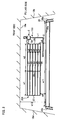
- FIG. 1 illustrates a right upper area of a backlite 12 including a glass antenna.
- an antenna conductor 100 for supplying power to the plural heater lines are provided, and the plural heater lines and the plural bus bars together form a defogger 30.
- FIG. 18 is a plan view of the glass antenna 100 for receiving waves of a first broadcasting frequency band and a second broadcasting frequency band higher than the first broadcasting frequency band.
- the glass antenna 100 includes an antenna conductor and a feeding part provided in/on the window glass 12.
- the window glass antenna 100 has a structure including, as the antenna conductor, a loop element 5 formed in the shape of a loop; an L-shaped element composed of a first antenna element of an antenna element 1 extending from a first point 5a disposed on the loop element 5 in a first direction substantially perpendicular to the horizontal direction and a second antenna element of an antenna element 2 extending in a second direction substantially perpendicular to the first direction from a first end point 1g corresponding to the end of extension in the first direction of the antenna element 1; and a connection element 6 extending from a second point 5b disposed on the loop element 5 in a third direction corresponding to a direction away from the L-shaped element (that is, a direction opposite by 180 degrees to the first direction in FIG.
- the L-shape herein includes a shape laterally symmetrical to the shape of L, and a corner of the L-shape may be bent with a curvature.
- an end point may be an end of the extension of the antenna element or a conductor portion disposed before and in the vicinity of the end.
- the glass antenna 100 is a monopole antenna, and a received signal obtained by the antenna conductor may be-taken out from a positive side (a hot side) of the feeding part 18, and the thus obtained received signal is transmitted to a receiver (not shown).
- a vehicle body opening on which the window glass 12 is mounted or a portion in the vicinity of the body opening is preferably usable as ground (because what is called body earth can be thus attained).
- the glass antenna 100 is disposed in the vicinity of an upper flange 15e of the body opening.
- FIG. 18 illustrates the feeding part 18 formed in a rectangular shape.
- the connection point 6a connected to the connection element 6 is disposed on the lower side of the feeding part 18.
- the connection point 6a is disposed at the center of the lower side of the feeding part 18 in FIG. 18 , it may be disposed in an arbitrary position on the lower side or disposed on the point of intersection of the lower side with the right or left side.
- the connection element 6 extends between the feeding part 18 and the loop element 5 so as to connect the feeding part 18 and the loop element 5 to each other.
- the loop element 5 is an antenna conductor formed in the shape of a loop.
- the shape of a loop is not limited to the shape formed with a line having a constant line width but a part of the line may have a larger width as far as the line forms a loop.
- the shape of the loop element may be a circular shape, such as a circle, an approximate circle, an ellipse or an approximate ellipse, or a rectangular or polygonal shape, such as a square, an approximate square, a rectangle, an approximate rectangle, a parallelogram, an approximate parallelogram, a rhombus or an approximate rhombus.
- the loop element 5 is in the shape of a square in FIG. 18 .
- connection point 5a connected to the antenna element 1 and the connection point 5b connected to the connection element 6 are disposed on the conductor portion of the loop element 5.
- the connection point 5a is disposed on one side (i.e., a lower side in the illustrated case) of a virtual line extending in the horizontal direction through the center of gravity of the loop element 5 while the connection point 5b is disposed on the other side (i.e., an upper side in the illustrated case).
- the connection points 5a and 5b of FIG. 18 are disposed on a straight line parallel to the first direction.
- the connection point 5b is disposed at the center of the upper side of the loop element 5 in FIG. 18 , it may be disposed in an arbitrary position on the upper side or disposed on the point of intersection of the upper side with the left or right side of the loop element 5.
- connection point 5b connected to the connection element 6 may be disposed in an arbitrary position on the right or left side of the loop element 5.
- the antenna element 1 may extend from the connection point 5a in the downward direction (i.e., in the first direction) to the end point 1g.
- connection point 5a is disposed at the center of the lower side of the loop element 5 in FIG. 18 , it may be disposed in an arbitrary position on the lower side or disposed on the point of interconnection of the lower side with the left or right side of the loop element 5.
- the antenna element 2 may extend from the end point 1g in the leftward direction (i.e., in the second direction) to an end point 2g. Alternatively, it may extend rightward (namely, in a direction opposite to the second direction by 180 degrees).
- the extending direction of the antenna element 2 (namely, the second direction) is preferably parallel or substantially parallel to the horizontal direction with the window glass 12 mounted on the body opening because the antenna gain may be thus improved as compared with the case where the direction is not parallel.
- a reference numeral 30a denotes an uppermost heater line and a reference numeral 30b denotes a bus bar.
- a reference numeral 20A denotes an example of the glass antenna for receiving AM broadcasting disposed in a vacant area above the defogger 30.
- an independent conductor not DC connected to but disposed in the vicinity of the antenna conductor 100 (that is, the AM glass antenna 20A in the exemplary case of FIG. 1 ) is preferably provided in a vacant area disposed on a side of the antenna element 2 closer to the periphery of the window glass from the viewpoint of improvement of antenna gain in the L band.
- the independent conductor preferably includes a plurality of liner conductors extending in parallel to a reference direction (corresponding to the second direction in FIG. 1 ) and electrically connected to a second feeding part (not shown in FIG. 1 but is provided in, for example, a left end portion of the AM glass antenna 20A) different from the feeding part 18, and thus, the independent conductor may be used for receiving the frequency band of AM broadcasting.
- the independent conductor 20A includes a plurality of liner conductors 21 through 26 extending in parallel to the reference direction.
- at least one pair of adjacent liner conductors out of the plural liner conductors preferably has an open end opened toward the antenna conductor 100 between a leading end opposing the antenna conductor 100 of one liner conductor and the other liner conductor of the pair, and thus, antenna gain in the band III may be improved.
- the sum in length along a vertical direction substantially perpendicular to the reference direction of vertical spaces sandwiched between adjacent liner conductors (hereinafter referred to as vertical or first direction components) corresponding to open ends is preferably 30% or more of the sum in length along the vertical direction of vertical components sandwiched between leading ends opposing the antenna conductor of the uppermost liner conductor and the lowermost liner conductor out of the plural liner conductors because thus, the antenna gain in the band III may be improved. More preferably, the sum in length of the vertical components corresponding to open ends is 60% or more of the sum in length of all vertical components.
- each open end is a portion opened toward the antenna conductor along the vehicle width direction and is provided between the leading ends opposing the antenna conductor of one of adjacent liner conductors and the other liner conductor.
- liner conductors adjacent to each other may have a short-circuit portion connected through a short-circuit line extending from the leading end opposing the antenna conductor of at least one of the adjacent liner conductors.
- a length in the vertical direction substantially perpendicular to the reference direction of a vertical component corresponding to a short-circuit line connected to a leading end of a liner conductor disposed closest to the periphery of the window glass out of all the leading ends of the plural liner conductors opposing the antenna conductor is preferably 0.027 ⁇ ⁇ g1 or less because the antenna gain in the first broadcasting frequency band such as the band III may be thus improved. More preferably, the length is 0.022 ⁇ g1 or less.
- the center frequency is 207 MHz and the wavelength ⁇ g1 207 MHz is 927.5 mm
- the L band of 1452 through 1492 MHz
- the center frequency is 1472 MHz and the wavelength ⁇ g2 at 1472 MHz is 130.4 mm.
- the length in the first direction of a first direction component corresponding to a short-circuit line connected to a leading end closest to the periphery of the window glass out of all the leading ends opposing the antenna conductor of the plural liner conductors is preferably 25 mm or less and more preferably 20 mm or less from the viewpoint of the improvement of the antenna gain in the band III.
- the minimum distance in the reference direction between the antenna conductor and the independent conductor on the same horizontal plane is preferably 0.008 ⁇ g2 through 0.39 ⁇ g2 and more preferably 0.08 ⁇ g2 through 0.23 ⁇ g2 from the viewpoint of the improvement of the antenna gain of the antenna conductor.
- the minimum distance in the second direction between the antenna conductor and the independent conductor on the same horizontal plane is preferably 1 mm through 50 mm and more preferably 1 mm through 30 mm from the viewpoint of the improvement of the antenna gain of the antenna conductor.
- the glass antenna is preferably provided so that the antenna element 2 extends in a vacant area disposed between the independent conductor and the heater line 30a from the viewpoint of the improvement of the antenna gain.
- an antenna pattern for attaining high antenna gain in both the first broadcasting frequency band and the second broadcasting frequency band an antenna pattern additionally including an independent conductor 20D in a shape closely surrounding an antenna conductor 500 illustrated in FIG. 19 may be employed.
- the independent conductor 20D may be provided closely merely to a second direction side of the antenna conductor 500 or merely to a fourth direction side of the antenna conductor 500.
- FIG. 19 is a plan view of the dual-band glass antenna 500, that is, an antenna conductor for receiving waves of a first broadcasting frequency band and a second broadcasting frequency band higher than the first broadcasting frequency band.
- the glass antenna 500 includes an antenna conductor and a feeding part provided in the window glass 12.
- the glass antenna 500 has a structure including, as the antenna conductor, a first antenna element of an antenna element 1 extending from the feeding part 18 in a first direction substantially perpendicular to the horizontal direction; a second antenna element of an antenna element 2 extending in a second direction substantially perpendicular to the first direction (namely, in the horizontal direction) from an end point 1g corresponding to the end of the extension in the first direction of the antenna element 1; a third antenna element of an antenna element 3 extending in a third direction, that is, the opposite direction to the first direction (namely, a direction parallel to and opposite to the first direction, i.e., the upward direction opposite to the first direction by 180 degrees, in FIG.
- each corner of the antenna conductor may be bent with a curvature.
- the end point may be an end of extension of an antenna element or a conductor portion disposed before and in the vicinity of the end.
- the antenna element 1 may extend from a connection point 1s in the downward direction (i.e., the first direction) to the end point 1g.
- the antenna element 2 may extend from the end point 1g in the leftward direction (i.e., the second direction) to the end point 2g.
- the antenna element 2 may extend in the rightward direction (namely, a direction opposite to the second direction by 180 degrees).
- the extending direction of the antenna element 2 (namely, the second direction) is preferably parallel or substantially parallel to the horizontal direction with the window glass 12 mounted on a body opening because the antenna gain may be thus improved as compared with the case where the direction is not parallel.
- the antenna element 3 may extend from the end point 2g in the upward direction (i.e., the third direction) to the end point 3g.
- the antenna element 4 may extend from the end point 3g in the leftward direction (i.e., the second direction) to the end point 4g.
- the antenna element 4 may extend in the rightward direction in the same manner as the antenna element 2.
- the independent conductor 20D corresponds to a parasitic conductor for the antenna conductor 500.
- the independent conductor 20D may be, for example, an AM glass antenna for receiving AM broadcasting disposed in a vacant area above the defogger 30.
- the independent conductor 20D (that is, the AM antenna in the exemplary case of FIG. 9 ) not DC connected to but disposed close to the antenna conductor 500 is provided in a vacant area of the window glass 12, and the independent conductor 20D is preferably provided in a vacant area disposed on the second direction side of the antenna element 3 and in a vacant area disposed on the fourth direction side of the antenna element 1 because the antenna gain in the band III and the L band may be thus improved.
- the independent conductor 20D preferably includes a plurality of liner conductors extending in parallel to the reference direction (that is, the second direction in the exemplary case of FIG. 9 ) and electrically connected to a second feeding part (not shown in FIG. 9 and corresponding to, for example, a feeding part for an AM antenna) different from the feeding part 18, and thus, the independent conductor 20D may be used for receiving waves of the frequency band of the AM broadcasting.
- the antenna pattern of the independent conductor 20D provided as the AM antenna surrounds the first direction side, the second direction side and the fourth direction side of the antenna conductor 500 as a whole.
- the antenna conductor 500 is disposed in a vacant area 13 whose first direction side, second direction side and fourth direction side are surrounded with the pattern of the AM antenna.
- the independent conductor 20D includes a first liner conductor group composed of a plurality of liner conductors 21 through 26 disposed in the vacant area on the second direction side of the antenna element 3 and a second liner conductor group composed of a plurality of liner conductors 51 through 55 and 26 disposed in the vacant area on the fourth direction side of the antenna element 1.
- the liner conductor 26 runs through a vacant area disposed between the antenna element 2 and the defogger 30 so as to be provided in both the vacant area on the second direction side and the vacant area on the fourth direction side.
- the vacant area 13 where the antenna conductor 500 is provided is surrounded with the first liner conductor group and the second liner conductor group.
- reference numerals 21g through 25 g respectively denote leading ends (end points) opposing the antenna conductor 500 corresponding to ends of extension in the fourth direction of the liner conductors 21 through 25.
- Reference numerals 51g through 55g respectively denote leading ends (end points) opposing the antenna conductor 500 corresponding to ends of extension in the second direction of the liner conductors 51 through 55.
- At least one pair of adjacent liner conductors out of the plural liner conductors preferably has an open end opened toward the antenna conductor 500 between the leading end opposing the antenna conductor 500 of one liner conductor of the pair and the other liner conductor, and thus, antenna gain in the band III may be improved.
- the sum in length along a vertical direction substantially perpendicular to the reference direction of vertical components corresponding to open ends is preferably 30% or more of the sum in length along the vertical direction of vertical components sandwiched between the leading ends opposing the antenna conductor of the uppermost liner conductor and the lowermost liner conductor because thus, the antenna gain in the band III may be improved. More preferably, the sum in length of the vertical components corresponding to open ends is 60% or more of the sum in length of all vertical components.
- All liner conductors having leading ends opposing the antenna conductor out of the plural liner conductors are preferably opened (as open ends) toward a direction parallel to the vertical direction from the viewpoint of the improvement of the antenna gain.
- one open end opened toward the antenna conductor is formed between the leading end 21g and the leading end 22g.
- one open end opened toward the antenna conductor is formed between the leading end 55g and the liner conductor 26.
- the plural liner conductors included in the independent conductor 20D may have at least one short-circuit portion formed by connecting a leading end opposing the antenna conductor 500 of one liner conductor of an adjacent pair out of the plural liner conductors to the other liner conductor of the pair through a short-circuit line.
- one short-circuit portion is formed by connecting the leading end 21g and the leading end 22g to each other through a short-circuit line extending in a direction parallel to the first direction.
- one short-circuit portion is formed by connecting the leading end 55g and the liner conductor 26 to each other through a short-circuit line.
- a length in the first direction of a first direction component corresponding to a short-circuit line connected to a leading end closest to the periphery of the window glass out of all leading ends opposing the antenna conductor of the plural liner conductors is preferably 0.027 ⁇ g1 or less, and thus, the antenna gain in the first broadcasting frequency band such as the band III may be improved.
- the length is more preferably 0.022 ⁇ g1 or less.
- a length in the first direction of a first direction component corresponding to a short-circuit line connected to a leading end closest to the periphery of the window glass out of all leading ends opposing the antenna conductor of the plural liner conductors is preferably 25 mm or less and more preferably 20 mm or less from the viewpoint of the improvement of the antenna gain in the band III.
- the closest antenna element preferably overlaps the closest liner conductor, when the closest liner conductor is projected in the first direction, by a length of 0.043 ⁇ g1 or less and more preferably 0.011 ⁇ g1 or less because thus, the antenna gain in the first broadcasting frequency band
- the antenna conductor of this embodiment may be formed, as the antenna pattern for attaining high antenna gain in both the first broadcasting frequency band and the second broadcasting frequency band, in an antenna pattern as illustrated in FIG. 20 , in which the antenna element of FIG. 19 is further folded.
- FIG. 20 is a plan view of a dual-band glass antenna 600 corresponding to an antenna conductor for receiving waves of a first broadcasting frequency band and a second broadcasting frequency band higher than the first broadcasting frequency band.
- Like reference numerals are used to refer to like elements used in the structure of FIG. 19 and the description is omitted.
- the glass antenna 600 has a structure including, as the antenna conductor, antenna elements 1, 2, 3 and 4; a fifth antenna element of an antenna element 5 extending in the third direction from the end point 4g corresponding to the end of the extension in the second direction of the antenna element 4; and a sixth antenna element of an antenna element 6 extending in the fourth direction, that is, a direction opposite to the second direction (i.e., a direction parallel to and opposite to the second direction, namely, the rightward direction opposite to the second direction by 180 degrees, in FIG. 20 ) from an end point 5g corresponding to the end of extension in the third direction of the antenna element 5 to an end point 6g.
- the antenna element 6 extends to the end point 6g in a portion spaced from the feeding part 18 and the antenna element 1 so as not to cross the feeding part 18 and the antenna element 1.
- the feeding part 18 of this invention is electrically connected to a feeder line connected to a receiver.
- the feeding part 18 is connected to an amplifier provided on the vehicle for attaining body earth through ground of the amplifier.
- the AV line is easily attached to the feeding part 18.
- the feeding part 18 is electrically connected to an internal conductor of a coaxial cable, and an external conductor of the coaxial cable is electrically connected to the earth part.
- the coaxial cable can be easily attached to the feeding part 18 and the earth part.
- ground of the amplifier circuit may be electrically connected to a ground portion such as the external conductor of the coaxial cable with the input side of the amplifier circuit electrically connected to the feeding part 18 and with the output side of the amplifier circuit connected to the internal conductor of the coaxial cable.
- the shape of the feeding part 18 may be determined in accordance with the shape of a leading end of the feeder line directly attached to the feeding part 18 or the shape of a connection member used for connecting the feeder line to the feeding part 18 (for example, in accordance with the shape of a mounting surface or a contact terminal of a connector).
- a rectangular or polygonal shape such as a square, an approximate square, a rectangle or an approximate rectangle is preferred from the viewpoint of implementation.
- the feeding part 18 may be in a circular shape such as a circle, an approximate circle, an ellipse or an approximate ellipse.
- the aforementioned glass antenna is not provided with an auxiliary antenna conductor, which does not limit the invention.
- An auxiliary antenna element in a substantially T-shape, a substantially L-shape or a loop shape may be added through or not through a connection conductor to an antenna element for impedance matching, phase adjustment, directivity adjustment or the like.
- a glass antenna may be obtained by forming a conductive layer including an antenna conductor in or on a synthetic resin film and attaching the synthetic resin film having the conductive layer onto the interior or exterior surface of a window glass plate for a vehicle.
- a glass antenna may be obtained by attaching a flexible circuit board on which an antenna conductor has been formed onto the interior or exterior surface of a window glass plate for a vehicle.
- An angle at which the window glass plate is mounted on a vehicle is preferably 15 through 90 degrees and more preferably 30 through 90 degrees against the horizontal direction.
- An antenna conductor is formed by printing a paste including a conductive metal, such as a silver paste, onto the interior surface of a window glass plate and baking the printed paste.
- the method for forming an antenna conductor is not limited to this. Instead, a line or a foil of a conductive substance such as copper may be formed on the interior or exterior surface of a window glass plate, may be adhered onto a window glass with an adhesive or the like, or may be formed within a window glass.
- the feeding part 18 may be similarly formed.
- a part or the whole of an antenna conductor may be formed on the masking film.
- An example of the masking film is a ceramic film such as a black ceramic film.
- the portion of the antenna conductor formed on the masking film is invisible from the outside of the vehicle due to the masking film, resulting in obtaining a window glass with superior design.
- a portion including thin lines alone is visible from the outside of the vehicle, and hence, the resultant window glass is preferred from the viewpoint of design.
- FIG. 2 is a diagram illustrating a pattern including an AM glass antenna 20B, that is, a basic shape of the AM glass antenna.
- the basic dimensions of respective portions of the AM glass antenna 20B are as follows:
- vehicle high frequency glass antennas respectively employing, as the pattern shape of the AM glass antenna according to this invention, the pattern of the AM glass antenna 20A illustrated in FIG. 1 and the pattern of an AM glass antenna 20C illustrated in FIG. 3 are fabricated.
- the right leading ends of the liner conductors 21 through 26 are not connected to one another (namely, the right short-circuit line 29 of FIG. 2 is not formed), and hence, open ends 41 through 45 opened toward the glass antenna 100 in the vehicle width direction are formed.
- the dimensions and the pattern formed on the left-hand side are the same as those illustrated in FIG. 2 although omitted.
- the AM glass antenna 20C two open ends 42 and 44 opened toward the glass antenna 100 along the vehicle width direction are formed. Specifically, a short-circuit portion 29b for short-circuiting the liner conductors 22 and 23 and a short-circuit portion 29d for short-circuiting the liner conductors 24 and 25 are formed in the AM glass antenna 20C in positions shifted from its right end toward its center along the vehicle width direction, so as to form a meander pattern at the right end of the AM glass antenna 20C.
- FIG. 3 the dimensions and the pattern formed on the left-hand side are the same as those illustrated in FIG. 2 although omitted. In the pattern of FIG.
- antenna gain attained all around the vehicle is measured so as to calculate average antenna gain.
- the dimensions of the respective portions of the glass antenna 100 illustrated in FIG. 18 are as follows:
- the antenna gain is measured by radiating, with radio waves, a vehicle on which the window glass is mounted at 15 degrees against the horizontal direction with the vehicle rotated by 360 degrees per angle of 2 degrees.
- the radio waves are vertical polarization and varied in the frequency by 10 MHz in each of the ranges of the band III and the L band.
- the measurement is performed with the wave angle between the position for emitting the waves and the antenna conductor set to the horizontal direction (namely, with the wave angle set to 0 degree assuming that a plane parallel to the ground surface is regarded as 0 degree and that a direction toward the vertex is regarded as 90 degrees).
- the antenna gain is expressed with that of a half-wave dipole antenna as a reference (in both the band III and the L band) and is standardized with the gain of a half-wave dipole antenna regarded as 0 dB.
- FIG. 4 illustrates actually measured data of average values of the antenna gain of the glass antenna 100 in employing the respective patterns of the AM glass antenna.
- “Open” corresponds to data obtained by employing the pattern of FIG. 1
- “Short” corresponds to data obtained by employing the pattern of FIG. 2
- “Meander” corresponds to data obtained by employing the pattern of FIG. 3
- “Without-AM” corresponds to data obtained without providing the AM glass antenna.
- the AM glass antenna corresponding to the parasitic conductor for the glass antenna 100 is provided in the position on the upper side of the antenna element 2 and on the left side of the antenna element 1, the antenna gain in the L band is improved with the antenna gain in the band III kept high.
- the pattern in which at least a part of the right short-circuit line at the right end of the AM glass antenna is opened is preferred, and the pattern in which all the right leading ends have open ends (namely, the pattern of FIG. 1 ) is more preferred from the viewpoint of the improvement of the antenna gain of the glass antenna 100.
- the antenna gain of the glass antenna 100 attained all around the vehicle is measured for calculating average antenna gain with the minimum distance w10 (see FIG. 2 ) between the AM glass antenna and the glass antenna 100 varied.
- the average antenna gain is calculated with the antenna gain attained without providing the AM glass antenna used as a reference and with the antenna gain of "Without-AM" regarded as 0 dB.
- FIG. 5 illustrates actually measured data of average values of the antenna gain of the glass antenna 100 employing the pattern of FIG. 1 with the minimum distance w10 varied.
- FIG. 6 illustrates actually measured data of average values of the antenna gain of the glass antenna 100 employing the pattern of FIG. 3 with the minimum distance w10 varied.
- the antenna gain indicated by the ordinate corresponds to an average value of the antenna gain attained at every 10 MHz in the frequency band of 170 through 240 MHz corresponding to the band III and an average value of the antenna gain attained at every 10 MHz in the frequency band of 1450 through 1490 MHz corresponding to the L band.
- the antenna gain is increased as the minimum distance w10 is increased no matter whether the pattern of FIG. 1 is employed or the pattern of FIG. 3 is employed.
- the antenna gain in the L band is remarkably increased as the minimum distance w10 is increased as illustrated in FIG. 6 .
- high antenna gain may be attained by setting the minimum distance along the vehicle width direction between the AM glass antenna and the glass antenna 100 to 10 mm or more (and more preferably, 20 mm or more).
- the antenna gain the glass antenna 100 attained all around the vehicle is measured with a length Hb of the right short-circuit line 29 of the AM glass antenna 20B of FIG. 2 varied, so as to calculate average antenna gain in the same manner as in Example 2.
- the width of an opening provided at the right end of the AM glass antenna 20B is gradually increased from the upper side (namely, the right short-circuit line 29 is gradually eliminated from the upper side), and thus, the length Hb of the right short-circuit line 29 is varied.
- FIG. 7 illustrates actually measured data of average values of the antenna gain of the glass antenna 100 with the length Hb of the right short-circuit line 29 varied.
- the antenna gain indicated by the ordinate of FIG. 7 corresponds to an average value of the antenna gain attained at every 10 MHz in the frequency band of 170 through 240 MHz corresponding to the band III or an average value of the antenna gain attained at every 10 MHz in the frequency band of 1450 through 1490 MHz corresponding to the L band.
- the resultant pattern corresponds to the pattern of the AM glass antenna 20B illustrated in FIG. 2
- the resultant pattern corresponds to the pattern of the AM glass antenna 20A illustrated in FIG. 1 .
- the antenna gain in the band III is improved with the antenna gain in the L band kept high. Accordingly, when the AM glass antenna is provided, high antenna gain may be attained by setting the total length Hb along the first direction of the short-circuit line connecting the leading ends of the liner conductors 21 through 26 to 70% or less of a total vertical length H of vertical components sandwiched between the right leading end of the uppermost liner conductor 21 and the right leading end of the lowermost linear component 26.
- high antenna gain may be attained by setting the total width of open ends provided at the right end of the AM glass antenna 20B to 30% or more (and more preferably 60% or more) of the total length H of the vertical components sandwiched between the right leading end of the uppermost liner conductor 21 and the right leading end of the lowermost liner conductor 26.
- FIG. 8 illustrates actually measured data of average values of the antenna gain of the glass antenna 100 attained all around the vehicle with the length Hb and the position of the right short-circuit line 29 varied.
- the antenna gain is calculated by the same method as in Example 2.
- "20 mm short-circuited from upper end” corresponds to data obtained when merely the liner conductor 21 and the liner conductor 22 close to the upper flange 15a of the body opening are short-circuited through the right short-circuit line 29 and the liner conductors 22 through 26 have open ends.
- "20 mm opened from upper end” corresponds to data obtained when merely the liner conductor 21 and the liner conductor 22 close to the upper flange 15a of the body opening have an open end and the liner conductors 22 through 26 are mutually short-circuited through the right short-circuit line 29.
- the antenna gain in the band III is degraded even if the liner conductors 22 through 26 have open ends.
- the antenna gain in the band III is improved even if the liner conductors 22 through 26 are connected to the right short-circuit line 29.
- the length of the right short-circuit line 29 is preferably short.
- the total length along the first direction of first direction components corresponding to a short-circuit line connected to the liner conductor 21 close to the upper flange 15a of the body opening is preferably 0 through 0.19 ⁇ g2 and more preferably 0 through 0.15 ⁇ g2 on the basis of the data of FIG. 8 from the viewpoint of the improvement of the antenna gain.
- the length of the short-circuit line is preferably 0 mm through 25 mm and more preferably 0 mm through 20 mm from the viewpoint of the improvement of the antenna gain.
- a vehicle high frequency glass antenna is fabricated by providing a pattern including the glass antenna 500 of FIG. 19 surrounded with the independent conductor 20D on an actual backlite, and the antenna gain of the glass antenna 500 attained all around the vehicle is measured so as to calculate average antenna gain with short-circuit portions of the independent conductor 20D varied.
- the basic dimensions of the respective portions of the independent conductor 20D of FIG. 9 are as follows:
- each of patterns of the AM glass antennas 20E through 20H illustrated in FIGS. 10A through 10D is provided around the pattern of the glass antenna 500, and vehicle high frequency glass antennas respectively employing these patterns are fabricated.
- the omitted portions are the same as those illustrated in FIG. 9 .
- the antenna gain of each antenna attained all around the vehicle is measured, so as to calculate average antenna gain.
- the antenna gain is measured in the same manner as in Example 1.
- the dimensions of the respective portions of the glass antenna 500 of FIG. 19 are as follows:
- FIG. 11 illustrates actually measured data of average values of the antenna gain of the glass antenna 500 attained by employing the respective patterns of the independent conductor.
- "0” corresponds to data obtained by employing the pattern of FIG. 9 in which all the leading ends opposing the glass antenna 500 of the liner conductors are not DC short-circuited along the direction parallel to the first direction and have open ends opened toward the glass antenna along the vehicle width direction.
- "20" corresponds to data obtained by employing the pattern of FIG.
- the sum in length of first direction components closed by short-circuit lines corresponds to 100% of the total length of all first direction components formed between adjacent liner conductors out of the plural liner conductors.
- the sum in length of short-circuit portions corresponds to 80%
- the sum in length of short-circuit portions corresponds to 40%
- the pattern of FIG. 10D it corresponds to 20%.
- the antenna gain in the band III is improved even though the liner conductors 22 through 26 (or 52 through 56) are connected to a short-circuit line (as in the case of "80" of FIG. 11 ).
- the short-circuit line is preferably short.
- the total length of first direction components corresponding to a short-circuit line connected to the leading end 21g (or 51g) closest to a periphery 12a of the vehicle glass window 12 is preferably 0.027 ⁇ g1 or less and more preferably 0-022 ⁇ g1 or less from the viewpoint of the improvement of the antenna gain in the band III.
- the total length is preferably 25 mm or less and more preferably 20 mm or less.
- the antenna gain of the glass antenna 500 attained all around the vehicle is measured so as to calculate average antenna gain with an overlap length w18 in the vertical direction between the uppermost liner conductor 21 and the antenna element 4 varied.
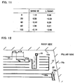
- FIG. 13 illustrates actually measured data of average values of antenna gain of the glass antenna 500 with the length w18 varied. It is noted that the antenna gain indicated by the ordinate corresponds to an average value of the antenna gain attained at every 10 MHz in the frequency band of 170 through 240 MHz corresponding to the band III or an average value of antenna gain attained at every 10 MHz in the frequency band of 1450 through 1490 MHz corresponding to the L band.
- the antenna gain in the band III is improved by setting the overlap length w18 to 40 mm or less and more preferably to 10 mm or less.
- the overlap length w18 is preferably less than 0 mm, namely, they do not preferably overlap, from the viewpoint of the improvement of the antenna gain in the band III.
- vehicle high frequency glass antennas are fabricated by respectively employing a pattern in which the glass antenna 600 of FIG. 20 is surrounded with an independent conductor 20I and a pattern in which the glass antenna 600 is not provided with an independent conductor, and the antenna gain of the glass antenna 600 attained all around the vehicle is measured so as to calculate average antenna gain with a short-circuit portion of the independent conductor 20I varied.
- the antenna gain is measured in the same manner as in Example 1.
- FIG. 14 is a diagram illustrating the pattern including the independent conductor 20I.
- the basic dimensions of respective portions of the independent conductor 20I are as follows:
- FIG. 15 illustrates actually measured data of average values of the antenna gain of the glass antennas 600 with the pattern of the independent conductor varied.
- "Open” corresponds to data obtained by employing the pattern of FIG. 14 in which all leading ends of the liner conductors opposing the pattern of the glass antenna 600 are not DC short-circuited in the direction parallel to the first direction but have open ends opened toward the glass antenna 600 in the vehicle width direction.
- “Short” corresponds to data obtained by employing a pattern in which all leading ends of the liner conductors opposing the pattern of the glass antenna 600 are DC short-circuited in the direction parallel to the first direction without forming any open end in the pattern of FIG. 14 .
- “Without-AM” corresponds to data obtained by employing the pattern of FIG. 20 without providing the independent conductor.
- the antenna gain in the band III and the L band may not be improved depending upon the pattern of the independent conductor.
- Example 6 when all the leading ends of the independent conductor are short-circuited, the antenna gain is degraded as compared with the case where the independent conductor is not provided, but when all the leading ends of the independent conductor are opened, the antenna gain in the band III and the L band is preferably improved to the equivalent level to that attained without providing the independent conductor.
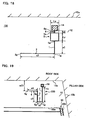
- an antenna conductor may be surrounded with an independent conductor as illustrated in FIG. 16 .
- a liner conductor 21 of an independent conductor 20J extends to a vacant area above the antenna element 6.
- FIG. 17 illustrates actually measured data of average values of antenna gain of the glass antenna 600 attained without providing it with the independent conductor and attained by surrounding it with the independent conductor.
- “Open” corresponds to data obtained by employing the pattern of FIG. 16 in which all leading ends of the liner conductors opposing the pattern of the glass antenna 600 are not DC short-circuited in the direction parallel to the first direction and have open ends opened toward the glass antenna 600 in the vehicle width direction.
- “Without-AM” corresponds to data obtained by employing the pattern of FIG. 20 not provided with the AM glass antenna.
- the antenna gain in both the band III and the L band is improved as compared with the case where the independent conductor is not provided.
Landscapes
- Details Of Aerials (AREA)
Claims (8)
- Eine Glasantenne für ein Fahrzeug, die Folgendes umfasst:einen Antennenleiter (500, 600);ein Einspeisungsteil (18), wobei der Antennenleiter (500, 600) mit dem Einspeisungsteil (18) verbunden ist; undeinen unabhängigen Leiter (20D - 20J), der vom Antennenleiter (500, 600) beabstandet ist und der eine Vielzahl an Deckleitern (liner conductors) (21 - 26, 51 - 55) beinhaltet, die parallel zu einer Bezugsrichtung verlaufen, wobei:der Antennenleiter (500, 600), das Einspeisungsteil (18) und der unabhängige Leiter (20D - 20J) mit einem Fensterglas (12) für das Fahrzeug versehen sind;dadurch gekennzeichnet, dassder Antennenleiter (500, 600) vom unabhängigen Leiter (20D - 20J) umgeben ist; und dassmindestens ein Paar benachbarte Deckleiter, aus einer Vielzahl von Deckleitern (21 - 26, 51 - 55), ein offenes Ende (41 - 45) aufweisen, das zum Antennenleiter (500, 600) hin geöffnet ist, zwischen vorderen Enden (21g - 25g, 51 g - 55g) gegenüber dem Antennenleiter der benachbarten Deckleiter.
- Die Glasantenne nach Anspruch 1, wobei
eine Summenbildung des Abstandes des offenen Endes (41 - 45) in Bezug auf die vertikale Richtung, im Wesentlichen orthogonal zur Bezugsrichtung 30% oder größer ist im Vergleich zu einem Abstand zwischen dem höchsten und dem niedrigsten Niveau der Vorderkanten der Vielzahl an Deckleitern (21 - 26, 51 - 55) auf der Seite des Antennenleiters (500, 600). - Die Glasantenne nach Anspruch 1 oder 2, wobei
im Falle, dass benachbarte Deckleiter aus einer Vielzahl von Deckleitern (21 - 26, 51 - 55) einen Kurzschlussabschnitt aufweisen, der über eine Kurzschlussleitung verbunden ist, die von einem vorderen Ende (21g - 25g, 51g - 55g) ausgeht gegenüber dem Antennenleiter (500, 600) von mindestens einem der benachbarten Deckleiter, dass ein erstes Sendefrequenzband und ein zweites Sendefrequenzband höher als das erste Sendefrequenzband bereitgestellt werden, dass die Wellenlänge in der Luft einer Mittenfrequenz des ersten Sendefrequenzbandes mit λ01 angegeben wird, dass der Verkürzungskoeffizient der Wellenlänge durch Glas durch k angegeben wird (wobei k = 0.64), und dass λg1 = λ01 * k, entspricht eine Länge der vertikalen Komponenten, die im Wesentlichen orthogonal zur Bezugsrichtung angeordnet sind, wobei die Länge einer Kurzschlussleitung (29, 29a) entspricht, die mit einem vorderen Ende (21 g, 51 g) verbunden ist, das einer Umfangskante (15a) des Fensterglases (12) am nächsten ist, aus allen vorderen Enden (21 g - 25g, 51g - 55g) der Vielzahl an Deckleitern (21- 26, 51 - 55) gegenüber dem Antennenleiter (500, 600), entspricht diese Länge also 0.027 * λg1 oder weniger. - Die Glasantenne nach irgendeinem der Ansprüche 1 bis 3, wobei
im Falle, dass benachbarte Deckleiter aus der Vielzahl an Deckleitern (21 - 26, 51 - 55) einen Kurzschlussabschnitt aufweisen, der über eine Kurzschlussleitung verbunden ist, die von einem vorderen Ende (21g - 25g, 51g - 55g) ausgeht gegenüber dem Antennenleiter (500, 600) von mindestens einem der benachbarten Deckleiter, entspricht eine Länge der vertikalen Komponenten, die im Wesentlichen orthogonal zur Bezugsrichtung angeordnet sind, wobei die Länge einer Kurzschlussleitung (29, 29a) entspricht, die mit einem vorderen Ende (21g, 51g) verbunden ist, das einer Umfangskante (15a) des Fensterglases (12) am nächsten ist, aus allen vorderen Enden (21g - 25g, 51g - 55g) der Vielzahl an Deckleitern (21- 26, 51 - 55) gegenüber dem Antennenleiter (500, 600), entspricht diese Länge also 25 mm oder weniger. - Die Glasantenne nach irgendeinem der Ansprüche 1 bis 4, wobei
im Falle, dass ein erstes Sendefrequenzband und ein zweites Sendefrequenzband höher als das erste Sendefrequenzband bereitgestellt werden, dass die Wellenlänge in der Luft einer Mittenfrequenz des ersten Sendefrequenzbandes mit λ01 angegeben wird, dass der Verkürzungskoeffizient der Wellenlänge durch Glas durch k angegeben wird (wobei k = 0.64), und dass λg1 = λ01 * k, dann überlappen einander ein am nächsten liegendes Antennenelement (4, 6), das einer Umfangskante (15a) des Fensterglases (12) am nächsten ist, aus Antennenelementen des Antennenleiters (500, 600), die sich in die zur Bezugsrichtung parallele Richtung erstrecken, und ein am nächsten liegender Deckleiter (21), der an der Umfangskante (15a) des Fensterglases (12) näher liegt als das am allernächsten liegende Antennenelement (4, 6) aus der Vielzahl an Deckleitern (21 - 26), um eine Länge von 0.043 * λg1 oder weniger, wenn der am allernächsten liegende Deckleiter (21) in die zur Bezugsrichtung im Wesentlichen orthogonale Richtung vorragt. - Die Glasantenne nach irgendeinem der Ansprüche 1 bis 4, wobei
ein am allernächsten liegendes Antennenelement (4, 6), das einer Umfangskante (15a) des Fensterglases (12) am nächsten ist, aus Antennenelementen des Antennenleiters (500, 600), die sich in die zur Bezugsrichtung parallele Richtung erstrecken, und der am nächsten liegende Deckleiter (21), der an der Umfangskante (15a) des Fensterglases (12) näher liegt als das am allernächsten liegende Antennenelement (4, 6) aus der Vielzahl an Deckleitern (21 - 26) einander um eine Länge von 40 mm oder weniger überlappen, wenn der am allernächsten liegende Deckleiter (21) in die zur Bezugsrichtung im Wesentlichen orthogonale Richtung vorragt. - Die Glasantenne nach irgendeinem der Ansprüche 1 bis 6, wobei die Bezugsrichtung eine horizontale oder im Wesentlichen horizontale Richtung ist, wenn der unabhängige Leiter (20D - 20J) im Fensterglas (12) bereitgestellt wird.
- Ein Fensterglas für ein Fahrzeug, das Folgendes umfasst:die Glasantenne nach irgendeinem der Ansprüche 1 bis 7.
Applications Claiming Priority (1)
| Application Number | Priority Date | Filing Date | Title |
|---|---|---|---|
| JP2008298797A JP5386944B2 (ja) | 2008-11-21 | 2008-11-21 | 車両用ガラスアンテナ及び車両用窓ガラス |
Publications (2)
| Publication Number | Publication Date |
|---|---|
| EP2190058A1 EP2190058A1 (de) | 2010-05-26 |
| EP2190058B1 true EP2190058B1 (de) | 2016-04-13 |
Family
ID=41688437
Family Applications (1)
| Application Number | Title | Priority Date | Filing Date |
|---|---|---|---|
| EP09014495.7A Active EP2190058B1 (de) | 2008-11-21 | 2009-11-20 | Glasantenne und Fensterglas für Fahrzeuge |
Country Status (2)
| Country | Link |
|---|---|
| EP (1) | EP2190058B1 (de) |
| JP (1) | JP5386944B2 (de) |
Families Citing this family (3)
| Publication number | Priority date | Publication date | Assignee | Title |
|---|---|---|---|---|
| JP5655522B2 (ja) * | 2010-11-24 | 2015-01-21 | 旭硝子株式会社 | 車両用アンテナ装置 |
| EP2709206B1 (de) | 2011-05-12 | 2019-10-30 | AGC Inc. | In eine windschutzscheibe integrierte antenne |
| JP5738177B2 (ja) * | 2011-12-28 | 2015-06-17 | 日本板硝子株式会社 | 車両用ガラスアンテナ |
Family Cites Families (8)
| Publication number | Priority date | Publication date | Assignee | Title |
|---|---|---|---|---|
| JPS61265902A (ja) | 1985-05-20 | 1986-11-25 | Toyota Motor Corp | 自動車用窓ガラスアンテナ |
| JPH0619205Y2 (ja) * | 1988-11-30 | 1994-05-18 | 日本板硝子株式会社 | 窓ガラスアンテナ |
| US5923298A (en) | 1997-04-30 | 1999-07-13 | Ford Motor Company | Multiband reception antenna for terrestrial digital audio broadcast bands |
| US6160518A (en) | 1999-04-02 | 2000-12-12 | Visteon Global Technologies, Inc. | Dual-loop multiband reception antenna for terrestrial digital audio broadcasts |
| JP3613097B2 (ja) | 1999-11-10 | 2005-01-26 | 日本板硝子株式会社 | 車両用ガラスアンテナ |
| JP2006197184A (ja) * | 2005-01-13 | 2006-07-27 | Asahi Glass Co Ltd | 車両用ガラスアンテナ |
| JP4410131B2 (ja) * | 2005-03-23 | 2010-02-03 | 日本板硝子株式会社 | 車両用ガラスアンテナ及び車両用ガラスアンテナを備える車両 |
| JP2008005474A (ja) * | 2006-05-23 | 2008-01-10 | Asahi Glass Co Ltd | 自動車用高周波ガラスアンテナ |
-
2008
- 2008-11-21 JP JP2008298797A patent/JP5386944B2/ja active Active
-
2009
- 2009-11-20 EP EP09014495.7A patent/EP2190058B1/de active Active
Also Published As
| Publication number | Publication date |
|---|---|
| JP5386944B2 (ja) | 2014-01-15 |
| EP2190058A1 (de) | 2010-05-26 |
| JP2010124444A (ja) | 2010-06-03 |
Similar Documents
| Publication | Publication Date | Title |
|---|---|---|
| EP2190057B1 (de) | Glasantenne und Fensterglas für Fahrzeuge | |
| CN102067378B (zh) | 玻璃天线 | |
| EP2173008B1 (de) | Hochfrequenz-glasantenne für fahrzeuge | |
| EP3101728B1 (de) | Scheibenantenne für ein fahrzeug und heckscheibenglas mit scheibenantenne für ein fahrzeug | |
| US8111202B2 (en) | High frequency wave glass antenna for an automobile and window glass sheet for an automobile with the same | |
| US9837699B2 (en) | Multi-element window antenna | |
| JP5141500B2 (ja) | 車両用ガラスアンテナ及び車両用窓ガラス | |
| EP2597726A1 (de) | Fahrzeugantenne | |
| US10290932B2 (en) | Glass antenna and vehicle window glass provided with glass antenna | |
| US9093751B2 (en) | Glass antenna for vehicle and window glass for vehicle | |
| US20050140549A1 (en) | High-bandwidth multi-band antenna | |
| US7071886B2 (en) | Glass antenna and glass antenna system for vehicles | |
| US20110012799A1 (en) | Glass antenna and window glass for vehicle | |
| JP5141503B2 (ja) | 車両用ガラスアンテナ及び車両用窓ガラス | |
| EP2190058B1 (de) | Glasantenne und Fensterglas für Fahrzeuge | |
| WO2023204158A1 (ja) | 車両用アンテナ装置 | |
| JP2023547508A (ja) | 車両用ガラスアンテナ | |
| WO2012049918A1 (ja) | アンテナ | |
| JP7794068B2 (ja) | 車両用窓ガラス | |
| US20250219285A1 (en) | Composite antenna device | |
| KR20090104743A (ko) | 자동차용 고주파 유리 안테나 및 자동차용 창유리판 |
Legal Events
| Date | Code | Title | Description |
|---|---|---|---|
| PUAI | Public reference made under article 153(3) epc to a published international application that has entered the european phase |
Free format text: ORIGINAL CODE: 0009012 |
|
| AK | Designated contracting states |
Kind code of ref document: A1 Designated state(s): AT BE BG CH CY CZ DE DK EE ES FI FR GB GR HR HU IE IS IT LI LT LU LV MC MK MT NL NO PL PT RO SE SI SK SM TR |
|
| AX | Request for extension of the european patent |
Extension state: AL BA RS |
|
| 17P | Request for examination filed |
Effective date: 20101126 |
|
| RAP1 | Party data changed (applicant data changed or rights of an application transferred) |
Owner name: ASAHI GLASS COMPANY, LIMITED |
|
| 17Q | First examination report despatched |
Effective date: 20120731 |
|
| REG | Reference to a national code |
Ref country code: DE Ref legal event code: R079 Ref document number: 602009037657 Country of ref document: DE Free format text: PREVIOUS MAIN CLASS: H01Q0001120000 Ipc: H01Q0005378000 |
|
| GRAP | Despatch of communication of intention to grant a patent |
Free format text: ORIGINAL CODE: EPIDOSNIGR1 |
|
| RIC1 | Information provided on ipc code assigned before grant |
Ipc: H01Q 1/12 20060101ALI20150922BHEP Ipc: H01Q 5/357 20150101ALI20150922BHEP Ipc: H01Q 9/42 20060101ALI20150922BHEP Ipc: H01Q 5/378 20150101AFI20150922BHEP |
|
| RIN1 | Information on inventor provided before grant (corrected) |
Inventor name: IKAWA, KOJI Inventor name: SUENAGA, KOUTAROU Inventor name: KAGAYA, OSAMU |
|
| INTG | Intention to grant announced |
Effective date: 20151019 |
|
| GRAS | Grant fee paid |
Free format text: ORIGINAL CODE: EPIDOSNIGR3 |
|
| GRAA | (expected) grant |
Free format text: ORIGINAL CODE: 0009210 |
|
| AK | Designated contracting states |
Kind code of ref document: B1 Designated state(s): AT BE BG CH CY CZ DE DK EE ES FI FR GB GR HR HU IE IS IT LI LT LU LV MC MK MT NL NO PL PT RO SE SI SK SM TR |
|
| REG | Reference to a national code |
Ref country code: GB Ref legal event code: FG4D |
|
| REG | Reference to a national code |
Ref country code: AT Ref legal event code: REF Ref document number: 791020 Country of ref document: AT Kind code of ref document: T Effective date: 20160415 Ref country code: CH Ref legal event code: EP |
|
| REG | Reference to a national code |
Ref country code: IE Ref legal event code: FG4D |
|
| REG | Reference to a national code |
Ref country code: DE Ref legal event code: R096 Ref document number: 602009037657 Country of ref document: DE |
|
| REG | Reference to a national code |
Ref country code: LT Ref legal event code: MG4D |
|
| REG | Reference to a national code |
Ref country code: AT Ref legal event code: MK05 Ref document number: 791020 Country of ref document: AT Kind code of ref document: T Effective date: 20160413 |
|
| REG | Reference to a national code |
Ref country code: NL Ref legal event code: MP Effective date: 20160413 |
|
| PG25 | Lapsed in a contracting state [announced via postgrant information from national office to epo] |
Ref country code: FI Free format text: LAPSE BECAUSE OF FAILURE TO SUBMIT A TRANSLATION OF THE DESCRIPTION OR TO PAY THE FEE WITHIN THE PRESCRIBED TIME-LIMIT Effective date: 20160413 Ref country code: NL Free format text: LAPSE BECAUSE OF FAILURE TO SUBMIT A TRANSLATION OF THE DESCRIPTION OR TO PAY THE FEE WITHIN THE PRESCRIBED TIME-LIMIT Effective date: 20160413 Ref country code: PL Free format text: LAPSE BECAUSE OF FAILURE TO SUBMIT A TRANSLATION OF THE DESCRIPTION OR TO PAY THE FEE WITHIN THE PRESCRIBED TIME-LIMIT Effective date: 20160413 Ref country code: LT Free format text: LAPSE BECAUSE OF FAILURE TO SUBMIT A TRANSLATION OF THE DESCRIPTION OR TO PAY THE FEE WITHIN THE PRESCRIBED TIME-LIMIT Effective date: 20160413 Ref country code: NO Free format text: LAPSE BECAUSE OF FAILURE TO SUBMIT A TRANSLATION OF THE DESCRIPTION OR TO PAY THE FEE WITHIN THE PRESCRIBED TIME-LIMIT Effective date: 20160713 |
|
| PG25 | Lapsed in a contracting state [announced via postgrant information from national office to epo] |
Ref country code: SE Free format text: LAPSE BECAUSE OF FAILURE TO SUBMIT A TRANSLATION OF THE DESCRIPTION OR TO PAY THE FEE WITHIN THE PRESCRIBED TIME-LIMIT Effective date: 20160413 Ref country code: PT Free format text: LAPSE BECAUSE OF FAILURE TO SUBMIT A TRANSLATION OF THE DESCRIPTION OR TO PAY THE FEE WITHIN THE PRESCRIBED TIME-LIMIT Effective date: 20160816 Ref country code: HR Free format text: LAPSE BECAUSE OF FAILURE TO SUBMIT A TRANSLATION OF THE DESCRIPTION OR TO PAY THE FEE WITHIN THE PRESCRIBED TIME-LIMIT Effective date: 20160413 Ref country code: GR Free format text: LAPSE BECAUSE OF FAILURE TO SUBMIT A TRANSLATION OF THE DESCRIPTION OR TO PAY THE FEE WITHIN THE PRESCRIBED TIME-LIMIT Effective date: 20160714 Ref country code: LV Free format text: LAPSE BECAUSE OF FAILURE TO SUBMIT A TRANSLATION OF THE DESCRIPTION OR TO PAY THE FEE WITHIN THE PRESCRIBED TIME-LIMIT Effective date: 20160413 Ref country code: AT Free format text: LAPSE BECAUSE OF FAILURE TO SUBMIT A TRANSLATION OF THE DESCRIPTION OR TO PAY THE FEE WITHIN THE PRESCRIBED TIME-LIMIT Effective date: 20160413 Ref country code: ES Free format text: LAPSE BECAUSE OF FAILURE TO SUBMIT A TRANSLATION OF THE DESCRIPTION OR TO PAY THE FEE WITHIN THE PRESCRIBED TIME-LIMIT Effective date: 20160413 |
|
| PG25 | Lapsed in a contracting state [announced via postgrant information from national office to epo] |
Ref country code: IT Free format text: LAPSE BECAUSE OF FAILURE TO SUBMIT A TRANSLATION OF THE DESCRIPTION OR TO PAY THE FEE WITHIN THE PRESCRIBED TIME-LIMIT Effective date: 20160413 Ref country code: BE Free format text: LAPSE BECAUSE OF FAILURE TO SUBMIT A TRANSLATION OF THE DESCRIPTION OR TO PAY THE FEE WITHIN THE PRESCRIBED TIME-LIMIT Effective date: 20160413 |
|
| REG | Reference to a national code |
Ref country code: DE Ref legal event code: R097 Ref document number: 602009037657 Country of ref document: DE |
|
| PG25 | Lapsed in a contracting state [announced via postgrant information from national office to epo] |
Ref country code: DK Free format text: LAPSE BECAUSE OF FAILURE TO SUBMIT A TRANSLATION OF THE DESCRIPTION OR TO PAY THE FEE WITHIN THE PRESCRIBED TIME-LIMIT Effective date: 20160413 Ref country code: CZ Free format text: LAPSE BECAUSE OF FAILURE TO SUBMIT A TRANSLATION OF THE DESCRIPTION OR TO PAY THE FEE WITHIN THE PRESCRIBED TIME-LIMIT Effective date: 20160413 Ref country code: EE Free format text: LAPSE BECAUSE OF FAILURE TO SUBMIT A TRANSLATION OF THE DESCRIPTION OR TO PAY THE FEE WITHIN THE PRESCRIBED TIME-LIMIT Effective date: 20160413 Ref country code: SK Free format text: LAPSE BECAUSE OF FAILURE TO SUBMIT A TRANSLATION OF THE DESCRIPTION OR TO PAY THE FEE WITHIN THE PRESCRIBED TIME-LIMIT Effective date: 20160413 Ref country code: RO Free format text: LAPSE BECAUSE OF FAILURE TO SUBMIT A TRANSLATION OF THE DESCRIPTION OR TO PAY THE FEE WITHIN THE PRESCRIBED TIME-LIMIT Effective date: 20160413 |
|
| PLBE | No opposition filed within time limit |
Free format text: ORIGINAL CODE: 0009261 |
|
| STAA | Information on the status of an ep patent application or granted ep patent |
Free format text: STATUS: NO OPPOSITION FILED WITHIN TIME LIMIT |
|
| PG25 | Lapsed in a contracting state [announced via postgrant information from national office to epo] |
Ref country code: SM Free format text: LAPSE BECAUSE OF FAILURE TO SUBMIT A TRANSLATION OF THE DESCRIPTION OR TO PAY THE FEE WITHIN THE PRESCRIBED TIME-LIMIT Effective date: 20160413 |
|
| 26N | No opposition filed |
Effective date: 20170116 |
|
| PG25 | Lapsed in a contracting state [announced via postgrant information from national office to epo] |
Ref country code: SI Free format text: LAPSE BECAUSE OF FAILURE TO SUBMIT A TRANSLATION OF THE DESCRIPTION OR TO PAY THE FEE WITHIN THE PRESCRIBED TIME-LIMIT Effective date: 20160413 |
|
| REG | Reference to a national code |
Ref country code: CH Ref legal event code: PL |
|
| PG25 | Lapsed in a contracting state [announced via postgrant information from national office to epo] |
Ref country code: LI Free format text: LAPSE BECAUSE OF NON-PAYMENT OF DUE FEES Effective date: 20161130 Ref country code: CH Free format text: LAPSE BECAUSE OF NON-PAYMENT OF DUE FEES Effective date: 20161130 |
|
| REG | Reference to a national code |
Ref country code: IE Ref legal event code: MM4A |
|
| REG | Reference to a national code |
Ref country code: FR Ref legal event code: ST Effective date: 20170731 |
|
| PG25 | Lapsed in a contracting state [announced via postgrant information from national office to epo] |
Ref country code: LU Free format text: LAPSE BECAUSE OF NON-PAYMENT OF DUE FEES Effective date: 20161130 |
|
| PG25 | Lapsed in a contracting state [announced via postgrant information from national office to epo] |
Ref country code: FR Free format text: LAPSE BECAUSE OF NON-PAYMENT OF DUE FEES Effective date: 20161130 |
|
| PG25 | Lapsed in a contracting state [announced via postgrant information from national office to epo] |
Ref country code: IE Free format text: LAPSE BECAUSE OF NON-PAYMENT OF DUE FEES Effective date: 20161120 |
|
| PGFP | Annual fee paid to national office [announced via postgrant information from national office to epo] |
Ref country code: GB Payment date: 20171123 Year of fee payment: 9 |
|
| PG25 | Lapsed in a contracting state [announced via postgrant information from national office to epo] |
Ref country code: CY Free format text: LAPSE BECAUSE OF FAILURE TO SUBMIT A TRANSLATION OF THE DESCRIPTION OR TO PAY THE FEE WITHIN THE PRESCRIBED TIME-LIMIT Effective date: 20160413 Ref country code: HU Free format text: LAPSE BECAUSE OF FAILURE TO SUBMIT A TRANSLATION OF THE DESCRIPTION OR TO PAY THE FEE WITHIN THE PRESCRIBED TIME-LIMIT; INVALID AB INITIO Effective date: 20091120 |
|
| PG25 | Lapsed in a contracting state [announced via postgrant information from national office to epo] |
Ref country code: IS Free format text: LAPSE BECAUSE OF FAILURE TO SUBMIT A TRANSLATION OF THE DESCRIPTION OR TO PAY THE FEE WITHIN THE PRESCRIBED TIME-LIMIT Effective date: 20160413 Ref country code: MK Free format text: LAPSE BECAUSE OF FAILURE TO SUBMIT A TRANSLATION OF THE DESCRIPTION OR TO PAY THE FEE WITHIN THE PRESCRIBED TIME-LIMIT Effective date: 20160413 Ref country code: MC Free format text: LAPSE BECAUSE OF FAILURE TO SUBMIT A TRANSLATION OF THE DESCRIPTION OR TO PAY THE FEE WITHIN THE PRESCRIBED TIME-LIMIT Effective date: 20160413 Ref country code: TR Free format text: LAPSE BECAUSE OF FAILURE TO SUBMIT A TRANSLATION OF THE DESCRIPTION OR TO PAY THE FEE WITHIN THE PRESCRIBED TIME-LIMIT Effective date: 20160413 |
|
| PG25 | Lapsed in a contracting state [announced via postgrant information from national office to epo] |
Ref country code: BG Free format text: LAPSE BECAUSE OF FAILURE TO SUBMIT A TRANSLATION OF THE DESCRIPTION OR TO PAY THE FEE WITHIN THE PRESCRIBED TIME-LIMIT Effective date: 20160413 |
|
| REG | Reference to a national code |
Ref country code: DE Ref legal event code: R082 Ref document number: 602009037657 Country of ref document: DE Representative=s name: MUELLER-BORE & PARTNER PATENTANWAELTE PARTG MB, DE Ref country code: DE Ref legal event code: R081 Ref document number: 602009037657 Country of ref document: DE Owner name: AGC INC., JP Free format text: FORMER OWNER: ASAHI GLASS COMPANY, LIMITED, TOKYO, JP |
|
| PG25 | Lapsed in a contracting state [announced via postgrant information from national office to epo] |
Ref country code: MT Free format text: LAPSE BECAUSE OF NON-PAYMENT OF DUE FEES Effective date: 20161120 |
|
| GBPC | Gb: european patent ceased through non-payment of renewal fee |
Effective date: 20181120 |
|
| PG25 | Lapsed in a contracting state [announced via postgrant information from national office to epo] |
Ref country code: GB Free format text: LAPSE BECAUSE OF NON-PAYMENT OF DUE FEES Effective date: 20181120 |
|
| PGFP | Annual fee paid to national office [announced via postgrant information from national office to epo] |
Ref country code: DE Payment date: 20251119 Year of fee payment: 17 |