EP2190372B1 - Schraubwerkzeug mit einem ratschenkopf mit elastischer umfassung - Google Patents
Schraubwerkzeug mit einem ratschenkopf mit elastischer umfassung Download PDFInfo
- Publication number
- EP2190372B1 EP2190372B1 EP08802216A EP08802216A EP2190372B1 EP 2190372 B1 EP2190372 B1 EP 2190372B1 EP 08802216 A EP08802216 A EP 08802216A EP 08802216 A EP08802216 A EP 08802216A EP 2190372 B1 EP2190372 B1 EP 2190372B1
- Authority
- EP
- European Patent Office
- Prior art keywords
- screw
- tool
- screw tool
- ratchet head
- actuating handle
- Prior art date
- Legal status (The legal status is an assumption and is not a legal conclusion. Google has not performed a legal analysis and makes no representation as to the accuracy of the status listed.)
- Not-in-force
Links
Images

Classifications
-
- B—PERFORMING OPERATIONS; TRANSPORTING
- B25—HAND TOOLS; PORTABLE POWER-DRIVEN TOOLS; MANIPULATORS
- B25B—TOOLS OR BENCH DEVICES NOT OTHERWISE PROVIDED FOR, FOR FASTENING, CONNECTING, DISENGAGING, OR HOLDING
- B25B13/00—Spanners; Wrenches
- B25B13/46—Spanners; Wrenches of the ratchet type, for providing a free return stroke of the handle
- B25B13/461—Spanners; Wrenches of the ratchet type, for providing a free return stroke of the handle with concentric driving and driven member
- B25B13/462—Spanners; Wrenches of the ratchet type, for providing a free return stroke of the handle with concentric driving and driven member the ratchet parts engaging in a direction radial to the tool operating axis
- B25B13/463—Spanners; Wrenches of the ratchet type, for providing a free return stroke of the handle with concentric driving and driven member the ratchet parts engaging in a direction radial to the tool operating axis a pawl engaging an externally toothed wheel
-
- A—HUMAN NECESSITIES
- A61—MEDICAL OR VETERINARY SCIENCE; HYGIENE
- A61B—DIAGNOSIS; SURGERY; IDENTIFICATION
- A61B17/00—Surgical instruments, devices or methods
- A61B17/56—Surgical instruments or methods for treatment of bones or joints; Devices specially adapted therefor
- A61B17/58—Surgical instruments or methods for treatment of bones or joints; Devices specially adapted therefor for osteosynthesis, e.g. bone plates, screws or setting implements
- A61B17/68—Internal fixation devices, including fasteners and spinal fixators, even if a part thereof projects from the skin
- A61B17/84—Fasteners therefor or fasteners being internal fixation devices
- A61B17/86—Pins or screws or threaded wires; nuts therefor
- A61B17/8605—Heads, i.e. proximal ends projecting from bone
- A61B17/861—Heads, i.e. proximal ends projecting from bone specially shaped for gripping driver
- A61B17/862—Heads, i.e. proximal ends projecting from bone specially shaped for gripping driver at the periphery of the screw head
-
- A—HUMAN NECESSITIES
- A61—MEDICAL OR VETERINARY SCIENCE; HYGIENE
- A61B—DIAGNOSIS; SURGERY; IDENTIFICATION
- A61B17/00—Surgical instruments, devices or methods
- A61B17/56—Surgical instruments or methods for treatment of bones or joints; Devices specially adapted therefor
- A61B17/58—Surgical instruments or methods for treatment of bones or joints; Devices specially adapted therefor for osteosynthesis, e.g. bone plates, screws or setting implements
- A61B17/88—Osteosynthesis instruments; Methods or means for implanting or extracting internal or external fixation devices
- A61B17/8875—Screwdrivers, spanners or wrenches
- A61B17/8877—Screwdrivers, spanners or wrenches characterised by the cross-section of the driver bit
- A61B17/8883—Screwdrivers, spanners or wrenches characterised by the cross-section of the driver bit the driver bit acting on the periphery of the screw head
-
- A—HUMAN NECESSITIES
- A61—MEDICAL OR VETERINARY SCIENCE; HYGIENE
- A61B—DIAGNOSIS; SURGERY; IDENTIFICATION
- A61B17/00—Surgical instruments, devices or methods
- A61B17/56—Surgical instruments or methods for treatment of bones or joints; Devices specially adapted therefor
- A61B17/58—Surgical instruments or methods for treatment of bones or joints; Devices specially adapted therefor for osteosynthesis, e.g. bone plates, screws or setting implements
- A61B17/88—Osteosynthesis instruments; Methods or means for implanting or extracting internal or external fixation devices
- A61B17/8875—Screwdrivers, spanners or wrenches
- A61B17/8886—Screwdrivers, spanners or wrenches holding the screw head
- A61B17/8891—Screwdrivers, spanners or wrenches holding the screw head at its periphery
-
- A—HUMAN NECESSITIES
- A61—MEDICAL OR VETERINARY SCIENCE; HYGIENE
- A61C—DENTISTRY; APPARATUS OR METHODS FOR ORAL OR DENTAL HYGIENE
- A61C8/00—Means to be fixed to the jaw-bone for consolidating natural teeth or for fixing dental prostheses thereon; Dental implants; Implanting tools
- A61C8/0089—Implanting tools or instruments
-
- B—PERFORMING OPERATIONS; TRANSPORTING
- B25—HAND TOOLS; PORTABLE POWER-DRIVEN TOOLS; MANIPULATORS
- B25B—TOOLS OR BENCH DEVICES NOT OTHERWISE PROVIDED FOR, FOR FASTENING, CONNECTING, DISENGAGING, OR HOLDING
- B25B13/00—Spanners; Wrenches
- B25B13/46—Spanners; Wrenches of the ratchet type, for providing a free return stroke of the handle
-
- B—PERFORMING OPERATIONS; TRANSPORTING
- B25—HAND TOOLS; PORTABLE POWER-DRIVEN TOOLS; MANIPULATORS
- B25B—TOOLS OR BENCH DEVICES NOT OTHERWISE PROVIDED FOR, FOR FASTENING, CONNECTING, DISENGAGING, OR HOLDING
- B25B23/00—Details of, or accessories for, spanners, wrenches, screwdrivers
- B25B23/14—Arrangement of torque limiters or torque indicators in wrenches or screwdrivers
- B25B23/142—Arrangement of torque limiters or torque indicators in wrenches or screwdrivers specially adapted for hand operated wrenches or screwdrivers
- B25B23/1422—Arrangement of torque limiters or torque indicators in wrenches or screwdrivers specially adapted for hand operated wrenches or screwdrivers torque indicators or adjustable torque limiters
- B25B23/1425—Arrangement of torque limiters or torque indicators in wrenches or screwdrivers specially adapted for hand operated wrenches or screwdrivers torque indicators or adjustable torque limiters by electrical means
-
- A—HUMAN NECESSITIES
- A61—MEDICAL OR VETERINARY SCIENCE; HYGIENE
- A61B—DIAGNOSIS; SURGERY; IDENTIFICATION
- A61B90/00—Instruments, implements or accessories specially adapted for surgery or diagnosis and not covered by any of the groups A61B1/00 - A61B50/00, e.g. for luxation treatment or for protecting wound edges
- A61B90/06—Measuring instruments not otherwise provided for
- A61B2090/064—Measuring instruments not otherwise provided for for measuring force, pressure or mechanical tension
-
- A—HUMAN NECESSITIES
- A61—MEDICAL OR VETERINARY SCIENCE; HYGIENE
- A61C—DENTISTRY; APPARATUS OR METHODS FOR ORAL OR DENTAL HYGIENE
- A61C1/00—Dental machines for boring or cutting ; General features of dental machines or apparatus, e.g. hand-piece design
- A61C1/08—Machine parts specially adapted for dentistry
- A61C1/18—Flexible shafts; Clutches or the like; Bearings or lubricating arrangements; Drives or transmissions
- A61C1/185—Drives or transmissions
- A61C1/186—Drives or transmissions with torque adjusting or limiting means
Definitions
- the invention relates to a screwing tool with a ratchet head and an actuating handle for use in medical technology, in particular dental prosthetics.
- ratchet allows in a known manner to tighten a screw in the smallest possible angular steps. It transmits pivotal movements of a lever in one direction only while the other direction is locked.
- ratchets consist of several parts, such as ratchet body, spring element, key holder, ratchet wheel, ratchet head, fixing pins and possibly more. For a necessary sterilization, all parts must be disassembled, sterilized and reassembled.
- EP 0704281B1 is a surgical torque wrench with indicator described. He has a ratchet on the head, which in turn consists of several individual and hollow parts. During sterilization parts can be lost or damaged. During the period of use, as a result of the sterilization, an increasing surface roughness can lead to additional friction and thus to a falsification of the desired torque.
- a one-piece ratchet which has a pawl spring in a channel-shaped clearance for the suspension of the pawl.
- the engagement of the spring-loaded pawl with the screwing tool is realized by jamming the pawl.
- the torque is indicated by the deformation of a bending eyelet.
- Arrangement and shape of pawl and pawl spring are extremely delicate, whereby a complex production of the ratchet is conditional.
- the display of the torque can be falsified.
- a screwing tool according to the features of the preamble of claim 1 is made WO-A-9936229 known.
- the object of the invention is therefore a substantial simplification of the ratchet head in order to achieve a simpler cleaning and sterilization at the same time lower production costs.
- the handling in confined spaces should be further improved.
- a screwing tool with a ratchet head and an actuating handle wherein the ratchet head has a receiving opening for insertion of a conventional, a substantially cylindrical handle with arranged on the lateral surface recesses driving tool and arranged at the periphery of the receiving opening spring-supported pawl, and wherein the pawl when engaging the ratchet head in Einschraubmodus with a recess of the screwdriving tool comes into engaging engagement and is solved upon actuation of the ratchet head in ratchet mode of the engaging engagement.
- the receiving opening is formed by an enclosure, on the inside of the pawl is arranged in one piece.
- the enclosure in the circumferential direction has an interruption and thus forms a flexurally elastic open ring as a spring for the pawl, at the first end of the pawl and at the second end of the actuating handle is arranged.
- ratchet head and operating handle are made in one piece, and thus disassembly for cleaning and sterilization can be omitted.
- the ratchet head can also be made separately to allow the use of different operating handles.
- the actuating handle comprises a torque integrator and / or indicator and / or limiter.
- the actuating handle is advantageously arranged radially at one end of the frame. Again, ratchet head and operating handle can be made together from one piece.
- the actuating handle is advantageously arranged axially at one end of the enclosure. Again, a one-piece design of ratchet head and operating handle is conceivable.
- the actuating handle consists of an at least partially hollow tube.
- sensors and electronics for a torque indicator can be housed inside the operating handle, ensuring easy cleaning and sterilization.
- the tube of the actuating handle is divided into an area that forms the actual handle, and a shaft between ratchet head and this actual handle.
- the actual grip can be rigid and the region of the shaft can be designed as a bending beam, which can ensure that the signal of a strain gauge accommodated in the shaft region is not distorted when the grip is actuated.
- the shaft advantageously contains one or more strain gauges, which are preferably mounted inside the hollow tube.
- the actuating handle for transmitting the signal of the strain gauges or for torque detection is connected to a measuring, display and documentation module.
- connection to the measuring, display and documentation module can be wired or wireless.
- a corresponding transmission unit is housed inside the tube for the radio transmission of the measurement signal.
- the interior of the operating handle is preferably completely encapsulated by means of a closure unit.
- the torque profile is continuously displayed, monitored and documented by the measuring, display and documentation module during a driving-in process.
- This may also include visual and visual, visual, auditory, or haptic signals, such as vibration, for monitoring and maintaining torque limits for the insertion torque input prior to insertion. Since this embodiment can basically also be used with differently designed screwing tools or tool heads, protection is sought for this and the following embodiment independently.
- the complete torque curve is stored during a driving-in process for documentation purposes in a patient data record.
- a so-called primary stability in dental medicine This refers to the torsional load capacity that an introduced implant has directly after the actual implantation. It corresponds to the recorded torque value at the end of the driving-in process.
- a doctor can thus give an account of the so-called insertion torque profile and the maximum torque load during and at the end of the insertion at any later time.
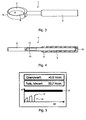
- Fig. 1 shows a plan view of a screwing tool 1 according to the invention with a ratchet head 2 and an operating handle 3.
- the ratchet head 2 has a receiving opening 4, which is surrounded by an enclosure 8.
- the enclosure 8 is for receiving a driving tool 5 (see Fig. 2 ) is annular and has at one point in the circumferential direction an interruption. In the area of this interruption on one side of the enclosure 8 a pawl 6 and on the other side an operating handle 3 is arranged.
- Pawl 6 and enclosure 8 are made in one piece, wherein the enclosure 8 takes over the suspension of the pawl.
- the spring force is determined by the material thickness of the enclosure 8 and by the choice of material and thus the material properties.
- Ratchet head 2 and operating handle 3 are made of one piece to facilitate cleaning and sterilization of the screwing tool 1. However, the ratchet head 2 can also be manufactured separately in order to be used in combination with various operating handles 3.
- Fig. 2 shows a side view of the screwing tool 1 according to the invention Fig. 1 with a likewise shown in a side view insertion tool 5.
- the insertion tool 5 has an upper part with a cylindrical handle whose lateral surface 14 has a plurality of recesses 7. Concentric with the cylindrical handle, the shank of the screwing tool extends with the tool blade 13. If the screwing tool 5 is inserted into the receiving opening 4 of the screwing tool 1, the catch 6 engages in one of the recesses 7. If the actuating handle 3 is moved in the screwing-in direction, there is a moving engagement between the pawl 6 and the recess 7.
- the enclosure 8 is bent by a wedging action of the pawl 6, so that the entraining engagement between pawl 6 and recess 7 is released.
- the reversal of the engaging direction of rotation takes place by simply repositioning the screwing tool 1.
- the screwing tool 1 can be used for various known screwing-in tools 5 are made by the shape of the pawl 6 is adjusted according to the recesses 7 of the respective insertion tool 5.
- the pawl 6 may also be designed such that it allows both left and right rotation. By appropriate shaping or material properties of the enclosure and a torque limiter can be set.
- Fig. 3 shows an isometric view of the already described screwing from the Fig. 1 and 2 ,
- Fig. 4 shows a sectional view of the side view of the screwing tool 1 from the Fig. 2 ,
- the section shows that the operating handle 3 is made of a hollow tube 9.
- the tube 9 is divided into two sections.
- a shaft 10 which is designed as a thin-walled bending beam.
- the subsequent rear part of the operating handle 3 is thick-walled and thus rigid.
- stiffening ribs or the like may additionally be provided.
- a strain gauge 11 is mounted in the interior of the tube 9 in order to enable the measurement of the shaft deflection and thus of the acting torque during the screwing operation.
- the signal of the strain gauge 11 is transmitted to a measurement, display and documentation module via a non-designated radio transmitter unit, which is likewise accommodated in the interior of the tube 9. Since the screwing tool 1 is designed in one piece for the purpose of simple cleaning and sterilization, the tube 9 of the actuating handle 3 is sealed by a closure unit 12.
- Fig. 5 shows an exemplary display of the measurement, display and documentation module. Shown is an example of a typical torque curve 15 during the insertion process of an implant, also called insertion or insertion, over time.
- the display further comprises the visual representation of the previously entered limit values 16 as well as limit value and current actual value in numbers.
- the change between screw-in mode and ratchet mode can be clearly seen in the torque curve 15. While the torque increases continuously during a screwing-in step, it drops to 0 Ncm in the ratchet mode. The highest torque value is usually reached at the end of the insertion.
- This final value 17 of the insertion moment profile provides information about the torsion loadability directly after the insertion, the so-called primary stability.
- the entire torque curve is combined with the entered Limits and the determined value of the primary stability in a patient-specific data record stored and archived.
Landscapes
- Health & Medical Sciences (AREA)
- Orthopedic Medicine & Surgery (AREA)
- Life Sciences & Earth Sciences (AREA)
- Engineering & Computer Science (AREA)
- Surgery (AREA)
- Animal Behavior & Ethology (AREA)
- General Health & Medical Sciences (AREA)
- Public Health (AREA)
- Veterinary Medicine (AREA)
- Mechanical Engineering (AREA)
- Heart & Thoracic Surgery (AREA)
- Medical Informatics (AREA)
- Molecular Biology (AREA)
- Nuclear Medicine, Radiotherapy & Molecular Imaging (AREA)
- Biomedical Technology (AREA)
- Neurology (AREA)
- Oral & Maxillofacial Surgery (AREA)
- Dentistry (AREA)
- Epidemiology (AREA)
- Details Of Spanners, Wrenches, And Screw Drivers And Accessories (AREA)
- Dental Prosthetics (AREA)
- Dental Tools And Instruments Or Auxiliary Dental Instruments (AREA)
Description
- Die Erfindung betrifft ein Schraubwerkzeug mit einem Ratschenkopf und einem Betätigungsgriff für die Anwendung in der Medizinaltechnik, insbesondere der Dentalprotetik.
- Die Zuverlässigkeit von Verschraubungen bei Implantaten bedingt eine genaue Einhaltung von Vorgaben für Vorspannkräfte, wie dem Drehmoment. Hierfür wird in der Regel ein Drehmomentschlüssel benutzt, der in der Regel zur besseren Handhabung bei beengten Platzverhältnissen mit einer Ratsche versehen ist. Eine Ratsche ermöglicht in bekannter Weise das Anziehen einer Verschraubung in möglichst kleinen Winkelschritten. Sie überträgt Schwenkbewegungen eines Hebels in nur einer Richtung, während die andere Richtung gesperrt ist. In der Regel bestehen Ratschen aus mehreren Teilen, wie Ratschenkörper, Federelement, Schlüsselhalter, Ratschrad, Ratschkopf, Fixierstiften und gegebenenfalls mehr. Für eine nötige Sterilisation müssen alle Teile demontiert, sterilisiert und wieder zusammengesetzt werden.
- Mit dem Patent
DE 19507535 wird eine Ratsche für medizinische Zwecke beschrieben, bei der sich auch ein vorgegebenes Drehmoment einstellen lässt. Diese Drehmomentenratsche weist viele Einzelteile auf und hat Dichtungen, um das Eindringen von Sterilisationsflüssigkeit zu verhindern. Sie entspricht nicht mehr den heutigen Möglichkeiten an die Rückführbarkeit von Montageparametern. - In der Patentschrift
EP 0704281 B1 ist ein chirurgischer Drehmomentenschlüssel mit Indikator beschrieben. Er weist am Kopf eine Ratsche auf, die wiederum aus mehreren Einzel- und Hohlteilen besteht. Bei der Sterilisation können Teile abhanden kommen oder beschädigt werden. Im Verlauf der Benutzungszeit kann infolge der Sterilisation eine zunehmende Oberflächenrauhigkeit zu zusätzlicher Reibung und damit zu einer Verfälschung des gewünschten Drehmoments führen. - Mit dem Gebrauchsmuster
DE 202004014195 U1 wird eine einteilige Ratsche beschrieben, die für die Federung der Klinke eine Klinkenfeder in einem kanalförmigen Spielraum aufweist. Der Eingriff der gefederten Klinke mit dem Eindrehwerkzeug wird über ein Verklemmen der Klinke realisiert. Das Drehmoment wird über die Verformung eines Biegeastes angezeigt. Anordnung und Formgebung von Klinke und Klinkenfeder sind äußerst filigran, wodurch eine aufwendige Fertigung der Ratsche bedingt ist. Auch die Reinigung und Sterilisation der Ratsche gestaltet sich dadurch schwierig. Teile aus der Umgebung können die Klinke verklemmen bzw. die Funktion der Klinke wesentlich beeinträchtigen. Zudem kann die Anzeige des Drehmoments verfälscht werden. - Ein Schraubwerkzeug gemäß den Merkmalen des Oberbegriffs des Anspruchs 1 ist aus
WO-A-9936229 - Neben den bereits genannten Nachteilen der aus dem Stand der Technik bekannten Ratschenwerkzeuge ist allen beschriebenen Instrumenten gemein, dass die Herstellkosten hoch sind, das Ergebnis eines in die Werkzeuge integrierten bzw. mit den Werkzeugen kombinierten Drehmomentanzeigegeräts verfälscht werden kann und sich die Reinigung und Sterilisation der Werkzeuge aufwendig gestaltet.
- Aufgabe der Erfindung ist deshalb eine wesentliche Vereinfachung des Ratschenkopfes, um eine einfachere Reinigung und Sterilisation bei gleichzeitig geringeren Herstellkosten zu erreichen. Zudem soll die Handhabbarkeit bei beengten Platzverhältnissen weiter verbessert werden. Außerdem soll sichergestellt werden, dass das Ergebnis eines integrierten oder in Kombination verwendeten Drehmomentanzeigegeräts nicht verfälscht wird.
- Die Aufgabe wird erfindungsgemäß durch die Merkmale des Anspruchs 1 gelöst. Es wird ausgegangen von einem Schraubwerkzeug mit einem Ratschenkopf und einem Betätigungsgriff, wobei der Ratschenkopf eine Aufnahmeöffnung zum Einsetzen eines herkömmlichen, eine im Wesentlichen zylindrische Handhabe mit an deren Mantelfläche angeordneten Ausnehmungen aufweisenden Eindrehwerkzeugs und eine an der Peripherie der Aufnahmeöffnung angeordnete federgestützte Klinke aufweist, und wobei die Klinke bei Betätigung des Ratschenkopfs im Einschraubmodus mit einer Ausnehmung des Eindrehwerkzeugs in mitnehmenden Eingriff kommt und bei Betätigung des Ratschenkopfs im Ratschenmodus der mitnehmende Eingriff gelöst ist. Ferner wird die Aufnahmeöffnung von einer Umfassung gebildet, auf deren Innenseite die Klinke einstückig angeordnet ist. Erfindungsgemäß ist vorgesehen, dass die Umfassung in Umfangsrichtung eine Unterbrechung aufweist und somit einen biegeelastischen offenen Ring als Feder für die Klinke bildet, an dessen erstem Ende die Klinke und an dessen zweitem Ende der Betätigungsgriff angeordnet ist.
- Weitere vorteilhafte Ausgestaltungen der Erfindung sind Gegenstand der Unteransprüche.
- Reinigung und Sterilisation werden weiter vereinfacht, wenn Ratschenkopf und Betätigungsgriff aus oder in einem Stück gefertigt sind, und somit eine Demontage zur Reinigung und Sterilisation entfallen kann. Der Ratschenkopf kann auch separat gefertigt werden, um die Verwendung verschiedener Betätigungsgriffe zu ermöglichen.
- Vorteilhafterweise umfasst der Betätigungsgriff einen Drehmomentintegrator und/oder -anzeiger und/oder -begrenzer.
- Soll das Schraubwerkzeug als Ratsche üblicher Bauart zum Einsatz kommen, so ist der Betätigungsgriff vorteilhafterweise radial an einem Ende der Umfassung angeordnet. Auch hier können Ratschenkopf und Betätigungsgriff zusammen aus einem Stück gefertigt sein.
- Soll das Schraubwerkzeug wie ein Schraubendreher bedient werden können, so ist der Betätigungsgriff vorteilhafterweise axial an einem Ende der Umfassung angeordnet. Auch hier ist eine einteilige Ausführung von Ratschenkopf und Betätigungsgriff denkbar.
- In einer weiteren bevorzugten Ausführungsform besteht der Betätigungsgriff aus einem zumindest teilweise hohlem Rohr. So können Sensoren und Elektronik für ein Drehmomentanzeigegerät im Inneren des Betätigungsgriffs untergebracht werden, wodurch eine einfache Reinigung und Sterilisation gewährleistet ist.
- Vorteilhafterweise ist das Rohr des Betätigungsgriffs unterteilt in einen Bereich, der den eigentlichen Griff bildet, und einen Schaft zwischen Ratschenkopf und diesem eigentlichem Griff. Somit kann der eigentliche Griff biegesteif und der Bereich des Schaftes als Biegebalken ausgebildet sein, wodurch sichergestellt werden kann, dass das Signal eines im Schaftbereich untergebrachten Dehnungsmessstreifens bei Betätigung des Griffs nicht verfälscht wird.
- Der Schaft enthält vorteilhafterweise einen oder mehrere Dehnungsmessstreifen, die vorzugsweise im Inneren des hohlen Rohres angebracht sind.
- In einer weiteren bevorzugten Ausführungsform ist der Betätigungsgriff zur Übertragung des Signals des oder der Dehnungsmessstreifen und zur Drehmomenterfassung an ein Mess-, Anzeige- und Dokumentationsmodul angeschlossen.
- Der Anschluss an das Mess-, Anzeige- und Dokumentationsmodul kann dabei kabelgebunden oder drahtlos ausgeführt sein. Bei der drahtlosen Ausführung ist zur Funkübertragung des Messsignals eine entsprechende Sendeeinheit im Inneren des Rohres untergebracht. Um die Notwendigkeit einer Demontage des Betätigungsgriffs zur Reinigung und Sterilisation zu verhindern, ist das Innere des Betätigungsgriffs vorzugsweise mittels einer Verschlusseinheit vollständig verkapselt.
- In einer weiteren bevorzugten Ausführungsform wird der Drehmomentverlauf während eines Eindrehvorgangs durch das Mess-, Anzeige- und Dokumentationsmodul laufend angezeigt, überwacht und dokumentiert. Dies kann auch die Überwachung und Einhaltung von Grenzwerten für das Eindrehmoment, welche vor dem Eindrehvorgang eingegeben werden, durch visuelle Darstellung sowie visuelle, akustische oder auch haptische Signale, wie beispielsweise Vibration, beinhalten. Da diese Ausführungsform grundsätzlich auch bei anders gestalteten Schraubwerkzeugen bzw. Werkzeugköpfen zum Einsatz kommen kann, wird für diese und die folgende Ausführungsform selbstständig Schutz begehrt.
- Vorteilhafterweise wird der komplette Drehmomentverlauf während eines Eindrehvorgangs zu Dokumentationszwecken in einem Patientendatensatz abgespeichert. Um direkt im Anschluss an das Einsetzen eines Implantats eine qualitative Aussage treffen zu können, ob das Implantat richtig eingesetzt wurde, spricht man in der dentalen Medizin von einer sogenannten Primärstabilität. Damit ist die Torsionsbelastbarkeit gemeint, die ein eingebrachtes Implantat direkt nach dem eigentlichen Implantieren aufweist. Sie entspricht dem aufgezeichneten Drehmomentwert bei Beendigung des Eindrehvorgangs. Ein Arzt kann mit Hilfe des abgespeicherten Drehmomentverlaufs somit zu einem späteren Zeitpunkt jederzeit Rechenschaft über den sogenannten Insertionsmomentenverlauf sowie über die maximale Drehmomentsbelastung während und bei Beendigung der Insertion geben.
- Im Folgenden wird ein Ausführungsbeispiel des erfindungsgemäßen Schraubwerkzeugs anhand von Zeichnungen näher erläutert.
- Es zeigen:
- Fig. 1
- eine Draufsicht eines erfindungsgemäßen Schraubwerkzeugs mit einem Rat- schenkopf und einem Betätigungsgriff;
- Fig. 2
- eine Seitenansicht des Schraubwerkzeugs aus
Fig. 1 mit einem Eindrehwerk- zeug, welches in die Aufnahmeöffnung des Ratschenkopfes eingesteckt werden kann; - Fig. 3
- eine perspektivische Ansicht des Schraubwerkzeugs aus den
Fig. 1 und 2 ; - Fig. 4
- eine Schnittansicht der Seitenansicht des erfindungsgemäßen Schraubwerk- zeugs aus
Fig. 2 ; und - Fig.5
- eine beispielhafte Anzeige des Mess-, Anzeige- und Dokumentationsmoduls.
- Für die gesamte weitere Beschreibung gilt: Sind in einer Figur zum Zweck zeichnerischer Eindeutigkeit Bezugsziffern enthalten, aber im zugehörigen Beschreibungstext nicht erläutert, so wird auf deren Erwähnung in vorangehenden Figurenbeschreibungen Bezug genommen.
-
Fig. 1 zeigt eine Draufsicht eines erfindungsgemäßen Schraubwerkzeugs 1 mit einem Ratschenkopf 2 und einem Betätigungsgriff 3. Der Ratschenkopf 2 weist eine Aufnahmeöffnung 4 auf, die von einer Umfassung 8 umgeben ist. Die Umfassung 8 ist zur Aufnahme eines Eindrehwerkzeugs 5 (sieheFig. 2 ) ringförmig ausgebildet und weist an einer Stelle in Umfangsrichtung eine Unterbrechung auf. Im Bereich dieser Unterbrechung ist auf einer Seite der Umfassung 8 eine Klinke 6 und auf der anderen Seite ein Betätigungsgriff 3 angeordnet. Klinke 6 und Umfassung 8 sind einstückig ausgeführt, wobei die Umfassung 8 die Federung der Klinke übernimmt. Die Federkraft wird dabei durch die Materialstärke der Umfassung 8 sowie durch die Materialwahl und somit die Werkstoffeigenschaften festgelegt. Ratschenkopf 2 und Betätigungsgriff 3 sind aus einem Stück gefertigt, um Reinigung und Sterilisation des Schraubwerkzeugs 1 zu vereinfachen. Der Ratschenkopf 2 kann jedoch auch separat gefertigt werden, um in Kombination mit verschiedenen Betätigungsgriffen 3 verwendet werden zu können. -
Fig. 2 zeigt eine Seitenansicht des erfindungsgemäßen Schraubwerkzeugs 1 ausFig. 1 mit einem ebenfalls in einer Seitenansicht gezeigten Eindrehwerkzeug 5. Das Eindrehwerkzeug 5 hat einen oberen Teil mit einer zylindrischen Handhabe, deren Mantelfläche 14 mehrere Ausnehmungen 7 aufweist. Konzentrisch zur zylindrischen Handhabe verläuft der Schaft des Eindrehwerkzeugs mit der Werkzeugklinge 13. Wird das Eindrehwerkzeug 5 in die Aufnahmeöffnung 4 des Schraubwerkzeugs 1 eingesteckt, so greift die Klinke 6 in eine der Ausnehmungen 7 ein. Wird der Betätigungsgriff 3 in Einschraubrichtung bewegt, so besteht zwischen Klinke 6 und Ausnehmung 7 ein mitnehmender Eingriff. Wird der Betätigungsgriff 3 in der Gegenrichtung bewegt, so wird die Umfassung 8 durch eine Keilwirkung der Klinke 6 aufgebogen, so dass der mitnehmende Eingriff zwischen Klinke 6 und Ausnehmung 7 gelöst wird. Die Umkehr der eingreifenden Drehrichtung erfolgt durch einfaches Umstecken des Schraubwerkzeugs 1. Das Schraubwerkzeug 1 kann für verschiedene bekannte Eindrehwerkzeuge 5 gefertigt werden, indem die Formgebung der Klinke 6 entsprechend der Ausnehmungen 7 des jeweiligen Eindrehwerkzeugs 5 angepasst wird. Die Klinke 6 kann auch derart ausgebildet sein, dass sie sowohl Links- wie auch Rechtslauf zulässt. Durch entsprechende Formgebung bzw. Werkstoffeigenschaften der Umfassung kann auch eine Drehmomentbegrenzung eingerichtet werden. -
Fig. 3 zeigt eine isometrische Ansicht des bereits beschriebenen Schraubwerkzeugs aus denFig. 1 und 2 . -
Fig. 4 zeigt eine Schnittansicht der Seitenansicht des Schraubwerkzeugs 1 aus derFig. 2 . Der Schnitt zeigt, dass der Betätigungsgriff 3 aus einem hohlen Rohr 9 gefertigt ist. Das Rohr 9 ist in zwei Abschnitte unterteilt. Im Bereich des Ratschenkopfes 2 befindet sich ein Schaft 10, der als dünnwandiger Biegebalken ausgebildet ist. Der darauffolgende hintere Teil des Betätigungsgriffs 3 ist dickwandiger und somit biegesteif ausgeführt. Zur Verstärkung des hinteren Teils des Betätigungsgriffs 3 können zusätzlich Versteifungsrippen oder dergleichen vorgesehen werden. Im Bereich des Schaftes 10 ist im Inneren des Rohres 9 ein Dehnungsmessstreifen 11 angebracht, um die Messung der Schaftdurchbiegung und somit des wirkenden Drehmoments während des Eindrehvorgangs zu ermöglichen. Das Signal des Dehnungsmessstreifens 11 wird über eine nicht bezeichnete ebenfalls im Inneren des Rohres 9 untergebrachte Funksendeeinheit an ein Mess-, Anzeige- und Dokumentationsmodul übertragen. Da das Schraubwerkzeug 1 zum Zwecke einer einfachen Reinigung und Sterilisation einteilig ausgeführt ist, ist das Rohr 9 des Betätigungsgriffs 3 durch eine Verschlusseinheit 12 dicht verschlossen. -
Fig. 5 zeigt eine beispielhafte Anzeige des Mess-, Anzeige- und Dokumentationsmoduls. Dargestellt ist ein Beispiel eines typischen Drehmomentverlaufs 15 während des Eindrehvorgangs eines Implantats, auch Insertionsvorgang oder Insertion genannt, über der Zeit. Die Anzeige umfasst ferner die visuelle Darstellung der zuvor eingegebenen Grenzwerte 16 sowie Grenzwert und momentanen Istwert in Zahlen. Der Wechsel zwischen Einschraubmodus und Ratschenmodus ist dem Drehmomentverlauf 15 deutlich zu entnehmen. Während das Drehmoment während eines Einschraubschrittes kontinuierlich ansteigt, fällt es im Ratschenmodus auf den Wert 0 Ncm ab. Der höchste Drehmomentwert wird in der Regel am Ende der Insertion erreicht. Dieser Endwert 17 des Insertionsmomentenverlaufs gibt Aufschluss über die Torsions-Belastbarkeit direkt im Anschluss an die Insertion, der sog. Primärstabilität. Der gesamte Drehmomentverlauf wird zusammen mit den eingegebenen Grenzwerten und dem ermittelten Wert der Primärstabilität in einem Patienten-spezifischen Datensatz abgespeichert und archiviert.
Claims (15)
- Schraubwerkzeug (1) mit einem Ratschenkopf (2) und einem Betätigungsgriff (3), insbesondere für den Einsatz in der Medizinaltechnik, wobei der Ratschenkopf (2) eine Aufnahmeöffnung (4) zum Einsetzen eines herkömmlichen, eine im Wesentlichen zylindrische Handhabe mit an der Mantelfläche (14) angeordneten Ausnehmungen (7) aufweisenden Eindrehwerkzeugs (5) und eine an der Peripherie der Aufnahmeöffnung (4) angeordnete federgestützte Klinke (6) aufweist, wobei die Klinke (6) bei Betätigung des Ratschenkopfs (2) im Einschraubmodus mit einer Ausnehmung (7) des Eindrehwerkzeugs (5) in mitnehmenden Eingriff kommt und bei Betätigung des Ratschenkopfs (2) im Ratschenmodus der mitnehmende Eingriff gelöst ist, und wobei die Aufnahmeöffnung (4) von einer Umfassung (8) gebildet ist, auf deren Innenseite die Klinke (6) einstückig angeordnet ist,
dadurch gekennzeichnet, dass
die Umfassung (8) in Umfangsrichtung eine Unterbrechung aufweist und somit einen biegeelastischen offenen Ring als Feder für die Klinke (6) bildet, an dessen erstem Ende die Klinke (6) und an dessen zweitem Ende der Betätigungsgriff (3) angeordnet ist. - Schraubwerkzeug (1) nach Anspruch 1,
dadurch gekennzeichnet, dass
Ratschenkopf (2) und Betätigungsgriff (3) in einem Stück gefertigt sind. - Schraubwerkzeug (1) nach einem der vorstehenden Ansprüche,
dadurch gekennzeichnet, dass
der Betätigungsgriff (3) einen Drehmomentintegrator und/oder -anzeiger und/oder begrenzer umfasst. - Schraubwerkzeug (1) nach einem der vorstehenden Ansprüche,
dadurch gekennzeichnet, dass
der Betätigungsgriff (3) radial am Ratschenkopf (2) als Ratschengriff üblicher Bauart angeordnet ist. - Schraubwerkzeug (1) nach einem der Ansprüche 1 bis 3,
dadurch gekennzeichnet, dass
der Betätigungsgriff (3) axial am Ratschenkopf (2) als Schraubendrehergriff angeordnet ist. - Schraubwerkzeug (1) nach einem der Ansprüche 3 bis 5,
dadurch gekennzeichnet, dass
der Betätigungsgriff (3) ein zumindest teilweise hohles Rohr (9) umfasst. - Schraubwerkzeug (1) nach Anspruch 6,
dadurch gekennzeichnet, dass
das Rohr (9) einen Schaft (10) im Bereich des Ratschenkopfs (2) aufweist, wobei der Schaft (10) als Biegebalken ausgebildet ist. - Schraubwerkzeug (1) nach Anspruch 7,
dadurch gekennzeichnet, dass
der Schaft (10) mindestens einen Dehnungsmessstreifen (11) enthält. - Schraubwerkzeug (1) nach Anspruch 8,
dadurch gekennzeichnet, dass
der Betätigungsgriff (3) zur Übertragung des Signals des/der Dehnungsmessstreifen (11) und zur Drehmomenterfassung an ein Mess-, Anzeige- und Dokumentationsmodul angeschlossen ist. - Schraubwerkzeug (1) nach Anspruch 9,
dadurch gekennzeichnet, dass
der Anschluss an das Mess-, Anzeige- und Dokumentationsmodul kabelgebunden ausgeführt ist. - Schraubwerkzeug (1) nach Anspruch 9,
dadurch gekennzeichnet, dass
der Anschluss an das Mess-, Anzeige- und Dokumentationsmodul drahtlos ausgeführt ist. - Schraubwerkzeug (1) nach einem der Ansprüche 8 bis 11,
dadurch gekennzeichnet, dass
das Innere des Betätigungsgriffs (3) mittels einer Verschlusseinheit (12) vollständig verkapselt ist. - Schraubwerkzeug (1) nach einem der Ansprüche 9 bis 12,
dadurch gekennzeichnet, dass
das Mess-, Anzeige- und Dokumentationsmodul derart ausgelegt ist, dass der Drehmomentverlauf (15) während eines Eindrehvorgangs angezeigt, überwacht und dokumentiert wird. - Schraubwerkzeug (1) nach einem der Ansprüche 9 bis 13,
dadurch gekennzeichnet, dass
das Mess-, Anzeige- und Dokumentationsmodul derart ausgelegt ist, dass der Drehmomentverlauf (15) während eines Eindrehvorgangs in einem Patientendatensatz abgespeichert wird. - Schraubwerkzeug (1) nach einem der vorstehenden Ansprüche,
dadurch gekennzeichnet, dass
der innere Durchmesser der Umfassung (8) in Achsrichtung der Aufnahmeöffnung (4) konstant ist, so dass eine Umkehr der eingreifenden Drehrichtung durch einfaches Umstecken des Schraubwerkzeugs (1) erfolgen kann.
Applications Claiming Priority (4)
| Application Number | Priority Date | Filing Date | Title |
|---|---|---|---|
| DE202007012866U DE202007012866U1 (de) | 2007-09-14 | 2007-09-14 | Insertionsmoment Dokumentations-System |
| DE200720015689 DE202007015689U1 (de) | 2007-11-10 | 2007-11-10 | Mono-Ratschenkopf |
| DE102008046989A DE102008046989A1 (de) | 2007-09-14 | 2008-09-12 | Schraubwerkzeug mit einem Ratschenkopf und einem Betätigungsgriff |
| PCT/EP2008/007681 WO2009036943A1 (de) | 2007-09-14 | 2008-09-15 | Schraubwerkzeug mit einem ratschenkopf mit elastischer umfassung |
Publications (2)
| Publication Number | Publication Date |
|---|---|
| EP2190372A1 EP2190372A1 (de) | 2010-06-02 |
| EP2190372B1 true EP2190372B1 (de) | 2011-06-08 |
Family
ID=40149630
Family Applications (1)
| Application Number | Title | Priority Date | Filing Date |
|---|---|---|---|
| EP08802216A Not-in-force EP2190372B1 (de) | 2007-09-14 | 2008-09-15 | Schraubwerkzeug mit einem ratschenkopf mit elastischer umfassung |
Country Status (4)
| Country | Link |
|---|---|
| EP (1) | EP2190372B1 (de) |
| AT (1) | ATE511804T1 (de) |
| DE (1) | DE102008046989A1 (de) |
| WO (1) | WO2009036943A1 (de) |
Cited By (1)
| Publication number | Priority date | Publication date | Assignee | Title |
|---|---|---|---|---|
| EP3125798A4 (de) * | 2014-04-03 | 2017-11-29 | Mis-Implants Technologies Ltd | Drehbare befestigungsvorrichtung mit integriertem drehmomentbegrenzer |
Families Citing this family (7)
| Publication number | Priority date | Publication date | Assignee | Title |
|---|---|---|---|---|
| CN102413784B (zh) * | 2009-08-05 | 2014-07-16 | 奥林巴斯医疗株式会社 | 转矩扳手及超声波手术装置 |
| EP3375403A1 (de) | 2017-03-15 | 2018-09-19 | Ruetschi Technology AG | Medizinisches instrument zum halten und zum festziehen mit drehmomentregelung einer implantatvorrichtung mit gewinde und verpackung dafür |
| JP7090976B2 (ja) * | 2017-11-28 | 2022-06-27 | 株式会社松風 | ラッチ付きハンドルリング |
| EP3527328A1 (de) * | 2018-02-14 | 2019-08-21 | Ruetschi Technology AG | Einweginstrument zur drehmomentsteuerung beim anziehen einer implantatvorrichtung mit gewinde |
| WO2020127331A1 (de) * | 2018-12-19 | 2020-06-25 | Straumann Holding Ag | Dentalmedizinischer drehmomentschlüssel |
| ES2984677T3 (es) | 2019-03-13 | 2024-10-30 | Straumann Holding Ag | Llave dinamométrica dental |
| DE102019134654A1 (de) * | 2019-12-17 | 2021-06-17 | Dormakaba Deutschland Gmbh | Drehmomentanzeigevorrichtung |
Family Cites Families (7)
| Publication number | Priority date | Publication date | Assignee | Title |
|---|---|---|---|---|
| DE3721564A1 (de) * | 1986-07-02 | 1989-02-02 | Manfred Paul Lenz | Vorrichtung zur verhinderung unerwuenschter drehbewegungen bei drehbaren elementen und werkzeug zu deren anbringung |
| EP0704281B1 (de) | 1994-09-27 | 1998-08-19 | Institut Straumann Ag | Chirurgischer Drehmomentschlüssel mit einem Drehmomentindikator |
| DE19507535A1 (de) | 1995-03-03 | 1996-09-05 | Werner Dipl Ing Schwartz | Drehmomenten - Ratsche für medizinische Zwecke |
| US5557994A (en) * | 1995-07-17 | 1996-09-24 | Nakayama; Tatsuo | Ratchet handle with torque adjustment |
| EP1077792A4 (de) * | 1998-01-20 | 2007-04-25 | Tool Design Corporation Hand | Umkehrbarer ratschenschlüssel mit drehmomentkupplung |
| US6109150A (en) * | 1999-08-06 | 2000-08-29 | Saccomanno, Iii; Matthew | Torque indicating wrench |
| DE202004014195U1 (de) | 2004-09-13 | 2004-11-18 | Thommen Medical Ag | Drehmomentschlüssel als Ratscheninstrument für die Medizinaltechnik |
-
2008
- 2008-09-12 DE DE102008046989A patent/DE102008046989A1/de not_active Withdrawn
- 2008-09-15 AT AT08802216T patent/ATE511804T1/de active
- 2008-09-15 WO PCT/EP2008/007681 patent/WO2009036943A1/de not_active Ceased
- 2008-09-15 EP EP08802216A patent/EP2190372B1/de not_active Not-in-force
Cited By (1)
| Publication number | Priority date | Publication date | Assignee | Title |
|---|---|---|---|---|
| EP3125798A4 (de) * | 2014-04-03 | 2017-11-29 | Mis-Implants Technologies Ltd | Drehbare befestigungsvorrichtung mit integriertem drehmomentbegrenzer |
Also Published As
| Publication number | Publication date |
|---|---|
| DE102008046989A1 (de) | 2009-05-20 |
| WO2009036943A1 (de) | 2009-03-26 |
| ATE511804T1 (de) | 2011-06-15 |
| EP2190372A1 (de) | 2010-06-02 |
Similar Documents
| Publication | Publication Date | Title |
|---|---|---|
| EP2190372B1 (de) | Schraubwerkzeug mit einem ratschenkopf mit elastischer umfassung | |
| DE10057589C1 (de) | Fußschalter | |
| WO2016070875A1 (de) | Enossales einzelzahnimplantat | |
| EP2279708A1 (de) | Behälter für ein medizinisches Instrument oder Implantat, insbesondere ein dentalmedizinisches Instrument oder ein Dentalimplantat | |
| EP2281527A1 (de) | Adapter zum Übertragen eines Drehmoments auf den Aufbauteil eines Dentalimplantats | |
| EP0860148A2 (de) | Bajonettkupplung zum lösbaren Verbinden zweier Rohrschaftinstrumente oder -instrumententeile | |
| DE202008004730U1 (de) | Modulare Femurkopfprothese | |
| EP2025296B1 (de) | Drehmomentschlüssel, insbesondere für den medizinischen Bereich | |
| EP1491294B1 (de) | Eindrehwerkzeug für Implantatschrauben | |
| DE112019000796T5 (de) | Einweginstrument zum drehmomentgesteuerten Festziehen einer mit einem Gewinde versehenen Implantatvorrichtung | |
| EP0450007B1 (de) | Vorrichtung zum halten von prothesen für die im- und explantation der prothese | |
| DE102017003184A1 (de) | Einrichtung zum Halten eines elektromagnetischen Sensors | |
| DE102018100664A1 (de) | Drehmomentwerkzeug | |
| EP3897447B1 (de) | Dentalmedizinischer drehmomentschlüssel | |
| EP2296574A1 (de) | Positionierhülse zum bohren mit einem chirurgischen bohrer und einer bohrschablone und system zum bohren | |
| EP3764950B1 (de) | Implantat | |
| EP2196165A1 (de) | Instrument zum Lösen eines Schraubenstumpfes einer Verbindungsschraube eines Zahnimplantats | |
| EP3958765B1 (de) | Set zur dorsalen wirbelfusion sowie handgriff für ein medizinisches werkzeug | |
| DE19850097A1 (de) | Verfahren und Einrichtung zur Handhabung von implantatgetragenem Zahnersatz | |
| DE112018001342T5 (de) | Medizinisches Instrument zum Halten und Festziehen mit gesteuertem Drehmoment einer Gewindeimplantatvorrichtung und Verpackung desselben | |
| DE202007015689U1 (de) | Mono-Ratschenkopf | |
| EP2399534A1 (de) | Extraktionswerkzeug für das Entfernen von Knochenschrauben, insbesondere in der Orthopädie oder der Unfallchirurgie | |
| EP2945562B1 (de) | Schaft eines dentalwerkzeugs | |
| EP0452623A2 (de) | Vorrichtung zum Spannen chirurgischer Schraubverbindungen | |
| EP2113221B1 (de) | Dentalimplantat aus keramischem Werkstoff |
Legal Events
| Date | Code | Title | Description |
|---|---|---|---|
| PUAI | Public reference made under article 153(3) epc to a published international application that has entered the european phase |
Free format text: ORIGINAL CODE: 0009012 |
|
| 17P | Request for examination filed |
Effective date: 20100311 |
|
| AK | Designated contracting states |
Kind code of ref document: A1 Designated state(s): AT BE BG CH CY CZ DE DK EE ES FI FR GB GR HR HU IE IS IT LI LT LU LV MC MT NL NO PL PT RO SE SI SK TR |
|
| AX | Request for extension of the european patent |
Extension state: AL BA MK RS |
|
| DAX | Request for extension of the european patent (deleted) | ||
| GRAP | Despatch of communication of intention to grant a patent |
Free format text: ORIGINAL CODE: EPIDOSNIGR1 |
|
| GRAS | Grant fee paid |
Free format text: ORIGINAL CODE: EPIDOSNIGR3 |
|
| GRAA | (expected) grant |
Free format text: ORIGINAL CODE: 0009210 |
|
| AK | Designated contracting states |
Kind code of ref document: B1 Designated state(s): AT BE BG CH CY CZ DE DK EE ES FI FR GB GR HR HU IE IS IT LI LT LU LV MC MT NL NO PL PT RO SE SI SK TR |
|
| REG | Reference to a national code |
Ref country code: GB Ref legal event code: FG4D Free format text: NOT ENGLISH |
|
| REG | Reference to a national code |
Ref country code: CH Ref legal event code: EP Ref country code: CH Ref legal event code: NV Representative=s name: BOVARD AG |
|
| REG | Reference to a national code |
Ref country code: IE Ref legal event code: FG4D Free format text: LANGUAGE OF EP DOCUMENT: GERMAN |
|
| REG | Reference to a national code |
Ref country code: DE Ref legal event code: R096 Ref document number: 502008003805 Country of ref document: DE Effective date: 20110721 |
|
| REG | Reference to a national code |
Ref country code: NL Ref legal event code: VDEP Effective date: 20110608 |
|
| PG25 | Lapsed in a contracting state [announced via postgrant information from national office to epo] |
Ref country code: LT Free format text: LAPSE BECAUSE OF FAILURE TO SUBMIT A TRANSLATION OF THE DESCRIPTION OR TO PAY THE FEE WITHIN THE PRESCRIBED TIME-LIMIT Effective date: 20110608 Ref country code: NO Free format text: LAPSE BECAUSE OF FAILURE TO SUBMIT A TRANSLATION OF THE DESCRIPTION OR TO PAY THE FEE WITHIN THE PRESCRIBED TIME-LIMIT Effective date: 20110908 Ref country code: SE Free format text: LAPSE BECAUSE OF FAILURE TO SUBMIT A TRANSLATION OF THE DESCRIPTION OR TO PAY THE FEE WITHIN THE PRESCRIBED TIME-LIMIT Effective date: 20110608 Ref country code: HR Free format text: LAPSE BECAUSE OF FAILURE TO SUBMIT A TRANSLATION OF THE DESCRIPTION OR TO PAY THE FEE WITHIN THE PRESCRIBED TIME-LIMIT Effective date: 20110608 |
|
| PG25 | Lapsed in a contracting state [announced via postgrant information from national office to epo] |
Ref country code: GR Free format text: LAPSE BECAUSE OF FAILURE TO SUBMIT A TRANSLATION OF THE DESCRIPTION OR TO PAY THE FEE WITHIN THE PRESCRIBED TIME-LIMIT Effective date: 20110909 Ref country code: LV Free format text: LAPSE BECAUSE OF FAILURE TO SUBMIT A TRANSLATION OF THE DESCRIPTION OR TO PAY THE FEE WITHIN THE PRESCRIBED TIME-LIMIT Effective date: 20110608 Ref country code: SI Free format text: LAPSE BECAUSE OF FAILURE TO SUBMIT A TRANSLATION OF THE DESCRIPTION OR TO PAY THE FEE WITHIN THE PRESCRIBED TIME-LIMIT Effective date: 20110608 Ref country code: ES Free format text: LAPSE BECAUSE OF FAILURE TO SUBMIT A TRANSLATION OF THE DESCRIPTION OR TO PAY THE FEE WITHIN THE PRESCRIBED TIME-LIMIT Effective date: 20110919 Ref country code: FI Free format text: LAPSE BECAUSE OF FAILURE TO SUBMIT A TRANSLATION OF THE DESCRIPTION OR TO PAY THE FEE WITHIN THE PRESCRIBED TIME-LIMIT Effective date: 20110608 Ref country code: CY Free format text: LAPSE BECAUSE OF FAILURE TO SUBMIT A TRANSLATION OF THE DESCRIPTION OR TO PAY THE FEE WITHIN THE PRESCRIBED TIME-LIMIT Effective date: 20110608 |
|
| PG25 | Lapsed in a contracting state [announced via postgrant information from national office to epo] |
Ref country code: NL Free format text: LAPSE BECAUSE OF FAILURE TO SUBMIT A TRANSLATION OF THE DESCRIPTION OR TO PAY THE FEE WITHIN THE PRESCRIBED TIME-LIMIT Effective date: 20110608 |
|
| REG | Reference to a national code |
Ref country code: IE Ref legal event code: FD4D |
|
| PG25 | Lapsed in a contracting state [announced via postgrant information from national office to epo] |
Ref country code: PT Free format text: LAPSE BECAUSE OF FAILURE TO SUBMIT A TRANSLATION OF THE DESCRIPTION OR TO PAY THE FEE WITHIN THE PRESCRIBED TIME-LIMIT Effective date: 20111010 Ref country code: EE Free format text: LAPSE BECAUSE OF FAILURE TO SUBMIT A TRANSLATION OF THE DESCRIPTION OR TO PAY THE FEE WITHIN THE PRESCRIBED TIME-LIMIT Effective date: 20110608 Ref country code: CZ Free format text: LAPSE BECAUSE OF FAILURE TO SUBMIT A TRANSLATION OF THE DESCRIPTION OR TO PAY THE FEE WITHIN THE PRESCRIBED TIME-LIMIT Effective date: 20110608 Ref country code: IE Free format text: LAPSE BECAUSE OF FAILURE TO SUBMIT A TRANSLATION OF THE DESCRIPTION OR TO PAY THE FEE WITHIN THE PRESCRIBED TIME-LIMIT Effective date: 20110608 Ref country code: IS Free format text: LAPSE BECAUSE OF FAILURE TO SUBMIT A TRANSLATION OF THE DESCRIPTION OR TO PAY THE FEE WITHIN THE PRESCRIBED TIME-LIMIT Effective date: 20111008 |
|
| PG25 | Lapsed in a contracting state [announced via postgrant information from national office to epo] |
Ref country code: PL Free format text: LAPSE BECAUSE OF FAILURE TO SUBMIT A TRANSLATION OF THE DESCRIPTION OR TO PAY THE FEE WITHIN THE PRESCRIBED TIME-LIMIT Effective date: 20110608 Ref country code: RO Free format text: LAPSE BECAUSE OF FAILURE TO SUBMIT A TRANSLATION OF THE DESCRIPTION OR TO PAY THE FEE WITHIN THE PRESCRIBED TIME-LIMIT Effective date: 20110608 Ref country code: SK Free format text: LAPSE BECAUSE OF FAILURE TO SUBMIT A TRANSLATION OF THE DESCRIPTION OR TO PAY THE FEE WITHIN THE PRESCRIBED TIME-LIMIT Effective date: 20110608 |
|
| BERE | Be: lapsed |
Owner name: TEICHMANN, MARTIN Effective date: 20110930 |
|
| PLBE | No opposition filed within time limit |
Free format text: ORIGINAL CODE: 0009261 |
|
| STAA | Information on the status of an ep patent application or granted ep patent |
Free format text: STATUS: NO OPPOSITION FILED WITHIN TIME LIMIT |
|
| PG25 | Lapsed in a contracting state [announced via postgrant information from national office to epo] |
Ref country code: MC Free format text: LAPSE BECAUSE OF NON-PAYMENT OF DUE FEES Effective date: 20110930 |
|
| 26N | No opposition filed |
Effective date: 20120309 |
|
| PG25 | Lapsed in a contracting state [announced via postgrant information from national office to epo] |
Ref country code: IT Free format text: LAPSE BECAUSE OF FAILURE TO SUBMIT A TRANSLATION OF THE DESCRIPTION OR TO PAY THE FEE WITHIN THE PRESCRIBED TIME-LIMIT Effective date: 20110608 |
|
| REG | Reference to a national code |
Ref country code: FR Ref legal event code: ST Effective date: 20120531 |
|
| PG25 | Lapsed in a contracting state [announced via postgrant information from national office to epo] |
Ref country code: DK Free format text: LAPSE BECAUSE OF FAILURE TO SUBMIT A TRANSLATION OF THE DESCRIPTION OR TO PAY THE FEE WITHIN THE PRESCRIBED TIME-LIMIT Effective date: 20110608 Ref country code: BE Free format text: LAPSE BECAUSE OF NON-PAYMENT OF DUE FEES Effective date: 20110930 |
|
| REG | Reference to a national code |
Ref country code: DE Ref legal event code: R097 Ref document number: 502008003805 Country of ref document: DE Effective date: 20120309 |
|
| PG25 | Lapsed in a contracting state [announced via postgrant information from national office to epo] |
Ref country code: FR Free format text: LAPSE BECAUSE OF NON-PAYMENT OF DUE FEES Effective date: 20110930 |
|
| PG25 | Lapsed in a contracting state [announced via postgrant information from national office to epo] |
Ref country code: MT Free format text: LAPSE BECAUSE OF FAILURE TO SUBMIT A TRANSLATION OF THE DESCRIPTION OR TO PAY THE FEE WITHIN THE PRESCRIBED TIME-LIMIT Effective date: 20110608 |
|
| GBPC | Gb: european patent ceased through non-payment of renewal fee |
Effective date: 20120915 |
|
| PG25 | Lapsed in a contracting state [announced via postgrant information from national office to epo] |
Ref country code: LU Free format text: LAPSE BECAUSE OF NON-PAYMENT OF DUE FEES Effective date: 20110915 |
|
| PG25 | Lapsed in a contracting state [announced via postgrant information from national office to epo] |
Ref country code: BG Free format text: LAPSE BECAUSE OF FAILURE TO SUBMIT A TRANSLATION OF THE DESCRIPTION OR TO PAY THE FEE WITHIN THE PRESCRIBED TIME-LIMIT Effective date: 20110908 |
|
| PG25 | Lapsed in a contracting state [announced via postgrant information from national office to epo] |
Ref country code: GB Free format text: LAPSE BECAUSE OF NON-PAYMENT OF DUE FEES Effective date: 20120915 |
|
| PG25 | Lapsed in a contracting state [announced via postgrant information from national office to epo] |
Ref country code: TR Free format text: LAPSE BECAUSE OF FAILURE TO SUBMIT A TRANSLATION OF THE DESCRIPTION OR TO PAY THE FEE WITHIN THE PRESCRIBED TIME-LIMIT Effective date: 20110608 |
|
| PG25 | Lapsed in a contracting state [announced via postgrant information from national office to epo] |
Ref country code: HU Free format text: LAPSE BECAUSE OF FAILURE TO SUBMIT A TRANSLATION OF THE DESCRIPTION OR TO PAY THE FEE WITHIN THE PRESCRIBED TIME-LIMIT Effective date: 20110608 |
|
| REG | Reference to a national code |
Ref country code: AT Ref legal event code: MM01 Ref document number: 511804 Country of ref document: AT Kind code of ref document: T Effective date: 20130915 |
|
| PG25 | Lapsed in a contracting state [announced via postgrant information from national office to epo] |
Ref country code: AT Free format text: LAPSE BECAUSE OF NON-PAYMENT OF DUE FEES Effective date: 20130915 |
|
| PGFP | Annual fee paid to national office [announced via postgrant information from national office to epo] |
Ref country code: CH Payment date: 20180924 Year of fee payment: 11 |
|
| PGFP | Annual fee paid to national office [announced via postgrant information from national office to epo] |
Ref country code: DE Payment date: 20180928 Year of fee payment: 11 |
|
| REG | Reference to a national code |
Ref country code: DE Ref legal event code: R119 Ref document number: 502008003805 Country of ref document: DE |
|
| REG | Reference to a national code |
Ref country code: CH Ref legal event code: PL |
|
| PG25 | Lapsed in a contracting state [announced via postgrant information from national office to epo] |
Ref country code: LI Free format text: LAPSE BECAUSE OF NON-PAYMENT OF DUE FEES Effective date: 20190930 Ref country code: DE Free format text: LAPSE BECAUSE OF NON-PAYMENT OF DUE FEES Effective date: 20200401 Ref country code: CH Free format text: LAPSE BECAUSE OF NON-PAYMENT OF DUE FEES Effective date: 20190930 |