EP2190607B1 - Machine-outil pour produire des dentures sur des pièces et procédé pour produire une denture sur une pièce au moyen d'une machine-outil - Google Patents
Machine-outil pour produire des dentures sur des pièces et procédé pour produire une denture sur une pièce au moyen d'une machine-outil Download PDFInfo
- Publication number
- EP2190607B1 EP2190607B1 EP08803126A EP08803126A EP2190607B1 EP 2190607 B1 EP2190607 B1 EP 2190607B1 EP 08803126 A EP08803126 A EP 08803126A EP 08803126 A EP08803126 A EP 08803126A EP 2190607 B1 EP2190607 B1 EP 2190607B1
- Authority
- EP
- European Patent Office
- Prior art keywords
- tool
- workpiece
- cold rolling
- machining
- chip removal
- Prior art date
- Legal status (The legal status is an assumption and is not a legal conclusion. Google has not performed a legal analysis and makes no representation as to the accuracy of the status listed.)
- Not-in-force
Links
- 238000000034 method Methods 0.000 title claims description 31
- 238000005097 cold rolling Methods 0.000 claims abstract description 176
- 238000003754 machining Methods 0.000 claims abstract description 69
- 238000005520 cutting process Methods 0.000 claims abstract description 42
- 238000004519 manufacturing process Methods 0.000 claims abstract description 9
- 238000006073 displacement reaction Methods 0.000 claims description 9
- 230000001360 synchronised effect Effects 0.000 claims description 6
- 230000001154 acute effect Effects 0.000 claims description 5
- 238000007493 shaping process Methods 0.000 claims 1
- 230000007704 transition Effects 0.000 description 34
- 238000005096 rolling process Methods 0.000 description 11
- 238000007790 scraping Methods 0.000 description 9
- 239000000463 material Substances 0.000 description 3
- 238000002360 preparation method Methods 0.000 description 2
- 230000000694 effects Effects 0.000 description 1
- 230000002349 favourable effect Effects 0.000 description 1
- 230000003014 reinforcing effect Effects 0.000 description 1
- 238000000926 separation method Methods 0.000 description 1
- 239000000758 substrate Substances 0.000 description 1
Images


Classifications
-
- B—PERFORMING OPERATIONS; TRANSPORTING
- B21—MECHANICAL METAL-WORKING WITHOUT ESSENTIALLY REMOVING MATERIAL; PUNCHING METAL
- B21H—MAKING PARTICULAR METAL OBJECTS BY ROLLING, e.g. SCREWS, WHEELS, RINGS, BARRELS, BALLS
- B21H5/00—Making gear wheels, racks, spline shafts or worms
- B21H5/02—Making gear wheels, racks, spline shafts or worms with cylindrical outline, e.g. by means of die rolls
- B21H5/027—Making gear wheels, racks, spline shafts or worms with cylindrical outline, e.g. by means of die rolls by rolling using reciprocating flat dies, e.g. racks
-
- Y—GENERAL TAGGING OF NEW TECHNOLOGICAL DEVELOPMENTS; GENERAL TAGGING OF CROSS-SECTIONAL TECHNOLOGIES SPANNING OVER SEVERAL SECTIONS OF THE IPC; TECHNICAL SUBJECTS COVERED BY FORMER USPC CROSS-REFERENCE ART COLLECTIONS [XRACs] AND DIGESTS
- Y10—TECHNICAL SUBJECTS COVERED BY FORMER USPC
- Y10T—TECHNICAL SUBJECTS COVERED BY FORMER US CLASSIFICATION
- Y10T409/00—Gear cutting, milling, or planing
- Y10T409/10—Gear cutting
- Y10T409/109699—Gear cutting with work clamping
Definitions
- the invention relates to a machine tool for producing toothings on workpieces, comprising a workpiece holding device, a cold rolling device for producing a raw toothing on at least one workpiece held by the workpiece holding device by cold rolling, and a chip processing device for machining fine machining of the raw toothing of the at least one workpiece, which is held on the workpiece holding device.
- the invention further relates to a method for producing a toothing on a workpiece by means of a machine tool, in which a workpiece is clamped to a workpiece holder.
- WO 01/94048 A1 From the WO 01/94048 A1 is a cold rolling machine with two counter-driven, profiled rolling rods, which are each mounted on a slide on a guide and which are in engagement with a rotatably mounted between the rolling rods tool known. It is provided with a feed device with at least one feed drive over which the rolling rods are adjustable during the rolling operation in the direction of engagement.
- a cold rolling machine which comprises a first movable roll bar holder and a second movable roll bar holder. Via the roll bar holders, a first roll bar and a second roll bar of a roll bar pair are movable in opposite directions to each other in a guide direction and are in a direction of displacement transverse to the guide direction during a rolling operation adjustable. There is provided a workpiece holding device with a plurality of workpiece holders.
- From the DE 26 04 281 A1 is a machine for scraping and / or profiling the teeth of gears with a rotating, toothed tool for finishing the teeth, a part for supporting the gear along the axis of rotation, a drive motor for the rotational movement of the Tool, and a device for effecting a mutual relative movement of the axes of rotation of the tool and the wheel to be machined known.
- the device at least two orthogonal movements can be generated by motors, each of which, as well as the drive motor for the rotational movement of the tool, has its own electronic control circuit connected to a setpoint generator.
- a tool for spin forming a workpiece with a toothing which has a profiling contour with tool teeth whose tooth height extends from a tool foot circle to a tool tip circle, between which tool tooth flanks are arranged, which as a negative to the force transmitting tooth flank regions of the workpiece are formed.
- a head-side end of the tool tooth flanks is clearly spaced from the tool head circle, on the tool tooth is formed between the head-side end of the tool tooth flanks and the tool tip circle, a head portion of the tool tooth, which tapers towards the tool tip circle, a foot-side end the tool tooth flanks are clearly spaced from the tool base circle, and between the foot-side ends of opposing tool tooth flanks of two tool teeth and the tool foot circle, a groove region is arranged, which tapers towards the tool base circle.
- the invention has for its object to provide a machine tool of the type mentioned, by means of which can produce teeth of high quality in a simple way.
- This task is based on the DE 2054740 According to the invention solved in that a transition means is provided, through which a workpiece from a cold rolling tool to a chip tool upon engagement of the raw toothing is transferable, and that the transition means has a toothing.
- a "cold rolling station” and a “chip processing station” are formed on a machine tool.
- a cold rolling process is a forming process in which the material of the workpiece is displaced into free spaces of the cold rolling tools.
- a rough toothing can be produced quickly by cold rolling.
- Subsequent chip processing gives a high quality of teeth.
- the quality of the teeth can be improved, for example, by (at least) 20 ⁇ m to 30 ⁇ m.
- corresponding workpieces can be used as gear teeth workpieces.
- the machine tool can be easily formed because the respective machining methods have similar kinematics as cold rolling methods.
- a transition device is provided, by means of which a workpiece can be transferred from a cold-rolling tool to a cutting tool upon engagement of the raw toothing. It can be achieved by the fact that the manufactured raw toothing does not get out of engagement with a tool toothing. As a result, the workpiece orientation is not lost. As a result, the fine machining can be carried out quickly, since no preparation time for the new discovery of the workpiece orientation is necessary.
- the transition means has a corresponding toothing to maintain the engagement.
- the transition device can be considered as a tool that allows the transition between cold rolling and machining.
- the workpiece holding device comprises at least one workpiece holder on which a workpiece is rotatably fixable about a workpiece axis. It can then in a cold rolling process and also in a Chip machining process a rotation of the workpiece driven by tools done.
- the workpiece holding device has at least one displacement device, by means of which a workpiece is displaceable coaxially or parallel to a workpiece axis in one direction. This makes it possible to transfer a workpiece by displacement of the workpiece holding device in the chip processing device.
- the workpiece holding device has at least one pivoting device, by means of which an angular position of a workpiece for the machining fine machining is adjustable. By pivoting the workpiece can be this with appropriate Transfer training of tools from the cold rolling device in the chip processing device.
- the angular position is adjustable relative to a movement axis of cold rolling tools.
- the axis of motion can, if circular tools are used, be an axis of rotation, or a linear axis, if oppositely moving flat tools are used.
- the angular position is adjustable relative to a chip tool.
- the defined chip machining can be performed as a fine machining.
- At least one cold rolling tool combination with the first cold rolling tool and the second cold rolling tool is provided, wherein the cold rolling tools are synchronously driven movable.
- the cold rolling tools are synchronously driven movable.
- the tool holding device is in particular designed such that at least one workpiece can be positioned between the first cold rolling tool and the second cold rolling tool.
- the first cold rolling tool and the second cold rolling tool are flat tools and in particular cold rolling rods. It is possible that the corresponding cold rolling rods have a uniform profile or a varying profile adapted to the raw toothing to be produced.
- the movement axis for the reciprocating movement of the first cold rolling tool and the second cold rolling tool is preferably perpendicular to a workpiece axis in order to effect a cold rolling.
- first cold rolling tool and the second cold rolling tool are round tools.
- a rotation axis is parallel to a workpiece axis.
- a feed device via which the first cold rolling tool and the second cold rolling tool can be delivered to the workpiece in a direction transverse to a workpiece axis. This makes it possible, for example, to use cold rolling rods with a uniform profile. It is in this context on the WO 01/94048 A1 referenced, to which reference is expressly made.
- the at least one cutting tool may, for example, be a scraper tool or an impact tool or skiving tool or hobbing tool or gear honing tool. It can then be carried out in time of the cold rolling process a fine machining a manufactured raw toothing in the same clamping.
- the at least one cutting tool is a flat tool or a round tool.
- an active surface of the at least one chip tool is oriented at an acute angle to a workpiece axis.
- the angle adjustment can be done by positioning and / or forming the at least one chip tool and / or positioning of the workpiece to be machined. In the latter case, for example, a pivoting of the workpiece takes place after the cold rolling process.
- the toothing of the transition device is designed such that it has such a large clearance and has such a small tooth width that the workpiece can be transferred from the cold rolling tool to the at least one chip tool without the workpiece coming out of engagement.
- the transition of the workpiece can be done by linear movement and / or pivoting.
- the transition device between the cold rolling tool and the at least one cutting tool is arranged to allow an effective and thus time-saving transition.
- At least one tool which has a cold rolling track as a profile track and a track for chip processing as a cutting track.
- a cold rolling process the cold rolling track is used, and during machining, the corresponding track is used for chip processing. The transition can then be carried out in a simple manner.
- a transition track (a transition device) is then arranged between the cold rolling track and the track track, in order to allow an effective transition of the workpiece, without having to disengage.
- the cold rolling track and the track track are arranged one behind the other with respect to a tool movement axis.
- tool movement during cold rolling only the cold rolling track is brought into operative engagement with the workpiece. After the completion of the cold rolling operation, such a shift occurs that only the chip track is engaged during machining.
- the cold rolling track and the chip track are arranged on a common strip and in particular form a combination tool.
- a certain area of this strip is brought into operative engagement with the workpiece.
- machining another area is brought into operative engagement.
- the bar can be easily moved by one or more carriages and in particular reciprocate.
- the cold rolling track and the chip track are arranged next to one another and in particular parallel with respect to a tool movement axis. In a cold rolling process then acts only the cold rolling track on the workpiece. For the chip track to be able to act on the workpiece, the workpiece or the tool must be displaced in the direction of separation of the cold rolling track and the chip track.
- the cold rolling track and the chip track are arranged on different bars. It is also possible in principle that they are arranged on the same strip and form a combination tool.
- the invention is further based on the object to provide a method of the type mentioned, with which can produce gears of high quality in an effective manner.
- a rough toothing is produced by cold rolling by means of a first cold rolling tool and a second cold rolling tool, the raw toothing is machined by means of at least one chip tool on the same machine tool in the same clamping and the workpiece to the at least one chip tool is moved over a transition toothing, wherein the transition teeth causes the workpiece remains engaged.
- the method according to the invention has the advantages already explained in connection with the machine tool according to the invention.
- the first cold rolling tool and the second cold rolling tool are synchronously moved.
- the synchronous movement can be an oppositely directed linear movement or a rotational movement in the same direction.
- the cold rolling tools are synchronized.
- the cold rolling tools are formed with a varying profile, which allows the preparation of the corresponding raw teeth. It is advantageous if the first cold rolling tool and the second cold rolling tool are delivered to the workpiece during cold rolling in a direction transverse to a tool movement axis and transversely to a workpiece axis become. As a result, for example, cold rolling rods with the same profile over the length of the cold rolling rods can be used to produce the raw toothing.
- the workpiece is rotatably clamped. It is then driven by the movement of the cold rolling tools, which are in operative engagement with the workpiece in its rotational movement.
- the workpiece is pivoted after cold rolling with a workpiece axis and / or moved linearly. This makes it possible to bring at least one cutting tool in engagement with the workpiece.
- the workpiece is moved to the at least one cutting tool on a transition toothing, wherein the transition toothing causes the workpiece remains in engagement.
- the fine machining is a butting and / or scraping and / or hobbing and / or hobbing and / or gear honing. This makes it possible to produce a toothing of high quality, which can be used for example as a gear toothing.
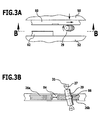
- FIG. 1 An embodiment of a machine tool according to the invention, which in FIG. 1 shown there and designated as a whole by 10, comprises a machine base frame 12, via which the machine tool 10 is set up on a substrate. With the machine base frame 12, a C-shaped frame 14 is connected.
- This frame 14 has a first holding region 16 and an opposite second holding region 18.
- the two holding regions 16 and 18 are connected to one another via a connecting region 20.
- the first holding region 16 protrudes beyond the connection region 20 in a transverse direction z.
- the second holding portion 18 protrudes beyond the connecting portion 20 in the transverse direction z.
- the first holding region 16 and the second holding region 18 thereby each form holding jaws, on each of which a first tool holder 22 (on the first holding region 16) and a second tool holder 24 (on the second holding region 18) are movably held.
- the two tool holders 22, 24 are opposite each other. One or more tools can be fixed to these.
- a workpiece holding device 25 is arranged with one or a plurality of workpiece holders 27 which are fixed on the connecting region 20 at least on one side ( FIG. 2 ).
- a workpiece 29 is used in each case, wherein it is rotatably supported by the workpiece holder about a workpiece axis 31 on the machine tool 10, so that a cold rolling process for producing a raw toothing on the workpiece 29 and a machining fine machining of the raw toothing feasible is.
- the connecting region 20 opposite a reinforcing tab 30 is disposed between the first holding portion 16 and the second holding portion 18. In the area of the workpiece holder, this has a continuous opening 32, through which tailstock parts of a workpiece holder 27 can in particular pass.
- the tool holders 22 and 24 are each movable in a longitudinal direction x and in the transverse direction y relative to the longitudinal direction x.
- first holding region 16 and the second holding region 18 each have an inclined guideway 34 or 36, on which a first wedge slide 38 or a second wedge slide 40 is guided.
- the guideway 34 is inclined with respect to the direction x by an acute angle.
- the guide track 36 of the second holding area 18 is parallel to the guide track 34 of the first holding area 16.
- the distance of the tool holder 22, 24 set in the direction y.
- recesses 42, 44 are formed in the holding areas 16 and 18, in which guide rails 46, 48 of the respective wedge slides 38, 40 are immersed.
- tools 26a, 26b and 28a, 28b can be aligned with a workpiece in the direction y.
- the tools 26a, 26b and 28a, 28b can be adjusted radially with respect to the workpiece during a rolling operation and during a machining fine machining.
- a first tool slide 50 is guided linearly displaceable in the direction x.
- a second tool slide 52 is guided linearly displaceably in the direction x on the second wedge slide 40, wherein the guide directions of the two tool slides 50, 52 are aligned in parallel.
- the tools 26 a, 26 b and 28 a, 28 b directly FIG. 2 ), ie are immovably fixed to these.
- the wedge slides 38, 40 have guideways 54, 56 facing each other. On each of these sit the tool slides 50, 52, wherein their movement is driven in the x direction.
- the corresponding drives are not shown in the drawing. It is in this context on the WO 01/94048 A1 respectively. US 2004/0007034 A1 Referenced.
- the tool slides 50 and 52 which are spaced apart in the y-direction, are driven in synchronism in opposite directions; upon movement of the tool carriage 50 in the + x direction, the other tool carriage 52 moves in the -x direction and vice versa.
- the tools 26a, 26b, 28a, 28b can be moved in the x-direction and y-direction via the tool holders 22, 24.
- the movement in the y-direction can be carried out in particular during a machining operation.
- the tool carriages 50 and 52 are driven driven on their respective guideways 54, 56.
- the wedge slides 38, 40 are driven driven on their respective guideways 34, 36.
- a tool carriage 50, 52 may hold a tool or a plurality of tools. If a plurality of tools are held, then different profile machining operations can be performed on a workpiece sequentially. In particular, different types of profiles can be introduced with appropriate tool training or a profile can be rough (by cold rolling) and fine machining (by machining), without an external tool change and a workpiece clamping must be performed.
- the tool carriage 52 (and corresponding to the tool carriage 50) has a fixing device for one or more tools.
- About the fixing device or the tools in an x-position, y-position and z-position on the tool carriage 52 are firmly positioned.
- several tools can be positioned one behind the other in the x-direction.
- a transverse offset in the z-direction is possible or a height offset in the y-direction is possible. This results in extensive possibilities for the production of profiles on a workpiece.
- the machine tool 10 has a control device 60 (in FIG FIG. 1 shown schematically).
- This control device 60 is arranged, for example, in a control box.
- the machine tool 10 can be controlled via the control device 60.
- the movement of the tool holders 22 and 24 in the direction x and the delivery in the direction y can be controlled.
- the position of the tool slides 50 and 52 can be controlled with respect to the selection of the tools (26a and 28a or 26b and / or 28b).
- a workpiece holder 27 comprises in each case a first abutment element 62 and a second abutment element 64 with respective abutment tips 66, 68, between which a workpiece 29 can be clamped.
- a clamped workpiece 29 is rotatable about the axis 70 of the corresponding workpiece holder 27.
- the axis 27 of the corresponding workpiece holder 64 lies between the tips 66 and 68.
- the axis of rotation 31 of a workpiece 29, which is clamped in the corresponding workpiece holder 27, is a workpiece axis and coincides with this axis 70.
- a workpiece holder 27 has, for example, a stationary headstock part, on which the first abutment element 62 is arranged or formed is. Furthermore, a workpiece holder 27 has a tailstock part, on which the second abutment element 64 is formed or arranged. The tailstock part is movable in a direction that is particularly parallel to the axis 70, movable. About the tailstock part can be a workpiece 29 in the associated workpiece holder 27 brace.
- the workpiece holder 27 can be displaceable and / or pivotable as a whole, as will be explained below.
- the workpiece holding device 25 comprises a pivoting device 72, via which the workpiece holder 27 is pivotable about a pivot axis 74 and thereby an angular position of the axis 70 and thus the workpiece axis is adjustable relative to the x-direction.
- the machine tool 10 comprises a cold rolling device 76, by means of which a rough toothing can be produced by cold rolling on the workpiece 29. Furthermore, it comprises a chip processing device 78, via which, after production of the raw toothing, fine machining of the raw toothing can be carried out by a metal-cutting process.
- a combination tool 80 which comprises the tools 26a and 26b is arranged on the first tool carriage 50.
- a tool 82 is arranged, which comprises the tools 28a and 28b.
- the tool 26a of the combination tool 80 is a cold rolling tool, in particular in the form of a cold rolling jaw with a profile which is predetermined by the raw toothing to be produced.
- the tool 26b of the combination tool 80 is a cutting tool such as a punch tool or a scraping tool.
- the tool 26a forms a first cold rolling tool.
- the tools 26a and 26b are arranged on the same bar of the combination tool 80, wherein they are arranged one behind the other in the x-direction and are spaced therefrom.
- a transition device 84 is arranged between the cold rolling tool 26a and the chip tool 26b.
- This is designed as a transition toothing, which allows a transition of the workpiece 29 from the first cold rolling tool 26a on the chip 26b without the workpiece 29 is disengaged, that is, the raw toothing on the workpiece 29, which via the cold rolling tools 26a and 28a has been manufactured, remains in engagement with the transition teeth 84 during the transfer into the toothing of the cutting tool 26b.
- the toothing of the transition device 84 based on the (raw) toothing of the workpiece 29, which is produced by cold rolling, such a large game and such a small tooth width, that the transition is made possible.
- the tool 28a is a second cold rolling tool.
- the tools 26a and 28a form a cold rolling tool combination, between which the workpiece 29 is positioned.
- the corresponding workpiece blank is clamped to the workpiece holder 27.
- the axis of rotation 31 and the workpiece axis 70 are aligned transversely and in particular perpendicular to the x-direction in the z-direction.
- the cold rolling tools 26a and 28a move in a synchronous manner in the x direction during a cold rolling operation, being delivered to the workpiece 29 in the y direction.
- the cutting tool 26b or 28b does not come into contact with the workpiece 29 during the cold rolling operation.
- the cold rolling process is in the FIGS. 2 (a), (b) and (c) schematically represents.
- the cold rolling tools 26a and 28a are moved synchronously in opposite directions via their respective workpiece slides 50 and 52.
- the cold rolling tools 26a and 28a have a profiling.
- the tools 26 a and 28 a simultaneously impinge on the workpiece 29.
- Cold rolling is a tensionless forming technique. Gears can be produced much faster with cold rolling than by machining.
- the tools 26a and 28a can be formed with a constant tread depth. It is in this context on the WO 01/94048 A1 and the WO 2006/045566 A1 Referenced.
- the combination tool 80 is displaced so that it is no longer in engagement with the workpiece 29.
- the workpiece 29 is brought via the pivoting device 72 in a pivotal position, that is, the axis 31 and thus the workpiece axis 70 is in a finite angle (angle not equal to 0 ° and not equal to 90 °) brought the x-direction.
- this finite angle is an acute angle.
- the cutting tool 26b is moved on the workpiece 29, wherein a delivery in the y-direction takes place.
- the cutting tool 26b performs a fine machining on the raw toothing. There is a rolling and a transverse movement. The cutting edges of the tool 26b are inclined to the workpiece 29.
- Fine machining improves the quality of the teeth. For example, it has been shown that the toothing quality for gear teeth during cold rolling is too low by approximately 20 ⁇ m to 30 ⁇ m. By machining with the tool 26b a gear quality is achieved, which is sufficient for example for gear teeth.
- the cutting tool 26b is designed, for example, as an impact tool or scraping tool.
- the cold rolling process and the machining process basically have a similar kinematics.
- the cold rolling can be performed on the same machine tool 10 via the cold rolling device 76 for producing the rough gear teeth 86 and the subsequent cutting fine machining by the chip processing device 78 without having to change the chucking (clamping) of the workpiece 29.
- the carriages 50 and 52 are synchronously reciprocated during cold rolling. During chip machining, the carriage 50, which holds the chip tool 26b, is moved back and forth. Both times there is a y-delivery to the workpiece.
- transition device 84 Via the transition device 84, a transition from the cold rolling tools 26a, 28a to the cutting tool 26b can be carried out, wherein the pivoting is made possible; the manufactured raw toothing 86 is not disengaged from the combination tool 80, so that the workpiece orientation is not lost.
- the tool carriages 50 and 52 are only moved such that the cold rolling tools 26a and 28a are in constant operative connection with the workpiece 29.
- the combination tool 80 (after moving away from the combination tool 82) is only moved so far that only the cutting tool 26b acts on the workpiece 29.
- both the combination tools 80 and 82 has a cutting tool.
- a uniform wear can be achieved if both the combination tools 80 and 82 each have a chip tool and for uniform tool wear these are used alternately (for different workpieces).
- the combination tool has traces lying one behind the other in the x-direction, namely the profile track of the cold rolling tool 26a and the Schnelldenspur of the cutting tool 26b, which are connected by the transition means 84.
- a first cold rolling tool 88 is held on the first tool carriage 50. Furthermore, a chip tool 90 is held parallel to the first cold rolling tool 88 on the first tool slide 50.
- the first cold rolling tool 88 has a profile track which lies parallel to a cutting track of the cutting tool 90.
- the first cold rolling tool 88 and the cutting tool 90 are formed on separate strips. It is also possible in principle that they are formed on the same strip and in particular are arranged on a combination tool.
- a workpiece holding device 94 on which the workpiece holder 27 is arranged (which basically has the same configuration as described above), has a displacement device 96, by means of which a workpiece is displaceable coaxially or parallel to the axis 70 of the workpiece holder 27, and in particular in the Direction is displaceable.
- a pivoting device corresponding to the pivoting device 72 is provided for adjusting the pivoting position of the workpiece axis 70 with respect to the x-direction.
- a transition device can be provided between the first cold rolling tool 88 and the cutting tool 90, in order to enable transfer without disengaging the toothing.
- the toothing production is carried out as described above, that is, it is first carried out on the cold rolling tools 88 and 92, a cold rolling process for producing the raw toothing 86. Then, the raw gear portion is brought into operative engagement with the cutting tool 90, which performs the fine machining of the raw toothing.
- the cutting tool 90 in turn is, for example, an impact tool or a scraping tool or hobbing tool or skiving tool or gear honing tool.
- the tools are flat tools (flat jaw tools) and in particular cold rolling rods and cutting bars (such as scraper bars).
- the cold rolling tool 98 it is also possible for the cold rolling tool 98 according to the invention to use a cold rolling rod as the first cold rolling tool 98 and also a cold rolling rod as the second cold rolling tool 100.
- a chip tool 102 a round tool is used, which is rotatable about an axis 104 and in particular rotatable.
- the axis 104 is arranged in particular at an angle (and in particular acute angle) to the axis 70 of the workpiece holder 27.
- a cold rolling process by means of the cold rolling bars 98 and 100 (FIG. FIG. 6 ). Subsequently, the produced raw toothing is brought into operative engagement with the cutting tool 104 by displacement in the z-direction. This then performs a machining fine machining of the raw toothing, for example by pushing or scraping.
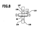
- first cold rolling tool 106 a round tool (cold rolling) is used and as a second cold rolling tool 108 also a round tool (cold roll) is used, which are rotatable about axes of rotation 107 and 109, respectively.
- the cutting tool 110 may be a flat tool or a round tool.
- a "conventional" cold rolling process is initially carried out with opposed cold-rolling tools driven oppositely in opposite directions (in the case of flat tools) or in the same direction (in circular tools).
- the cold rolling tools can be linear oppositely moving flat tools or cylindrical tools rotated in the same direction.
- the cold rolling process is a chipless forming process.
- a transition to a cutting tool such as a scraping tool or impact tool is performed in the same machine tool.
- the workpiece is linearly moved and / or pivoted by a transition device with a transition toothing.
- the cold rolling tools are brought out of operative engagement with the workpiece.
- chip machining takes place, which improves the quality of the teeth.
- the chip processing is carried out by linear movement (in particular reciprocating motion) of the cutting tool or by a rotational movement in each case with y-delivery. For example, by bumping and / or scraping and / or hobbing and / or skiving and / or gear honing to obtain a quality of the toothing, which is suitable for example for gear teeth.
- flat tools or round tools can be used for cold rolling.
- a suitable flat tool or round tool can be used for the fine machining.
- Cold rolling and chip processing are performed one after the other.
- a change in the angular position is necessary. This can be done by changing the angular position of the workpiece and / or by adjusting the angular position of the chip tool.
Landscapes
- Engineering & Computer Science (AREA)
- Mechanical Engineering (AREA)
- Gear Processing (AREA)
- Turning (AREA)
- Forging (AREA)
Claims (15)
- Machine-outil pour la réalisation de dentures sur des pièces (29), comprenant un dispositif de serrage de la pièce (25), un dispositif de laminage à froid (76) pour la réalisation d'une denture brute (86) par laminage à froid sur au moins une pièce (29) maintenue par le dispositif de serrage de la pièce (25), et un dispositif d'usinage par enlèvement de copeaux (78) pour le finissage par enlèvement de copeaux de la denture brute (86) de l'au moins une pièce (29) maintenue sur le dispositif de serrage de à pièce (25), caractérisée en ce qu'un dispositif de transfert (84) est prévu, au moyen duquel une pièce est transférable d'un outil de laminage à froid (26a) à un outil d'enlèvement de copeaux (26b) par engrènement de la denture brute (86), et en ce que le dispositif de transfert (84) comporte une denture.
- Machine-outil selon la revendication 1, caractérisée en ce que le dispositif de serrage de la pièce (25) comprend au moins un porte-pièce (27) sur lequel une pièce (29) peut être fixée de manière pivotante autour d'un axe de pièce.
- Machine-outil selon la revendication 1 ou la revendication 2, caractérisée en ce que le dispositif de serrage de la pièce (25) comporte au moins un dispositif de déplacement (96) au moyen duquel une pièce (29) peut être déplacée dans une direction coaxiale ou parallèle à un axe de pièce.
- Machine-outil selon l'une des revendications précédentes, caractérisée en ce que le dispositif de serrage de la pièce (25) comporte au moins un dispositif de pivotement (72) au moyen duquel il est possible de régler une position angulaire d'une pièce pour le finissage par enlèvement de copeaux.
- Machine-outil selon la revendication 4, caractérisée en ce que la position angulaire est réglable par rapport à un axe de déplacement de l'outil de laminage à froid (26a, 28a), et en particulier en ce que la position angulaire est réglable par rapport à l'outil d'enlèvement de copeaux (26b).
- Machine-outil selon l'une des revendications précédentes, caractérisée par au moins une combinaison d'outils de laminage à froid avec un premier outil de laminage à froid (26a ; 106) et un deuxième outil de laminage à froid (28a ; 108), déplaçables par entraînement synchrone, et caractérisée en particulier en ce qu'au moins une pièce est positionnable entre le premier outil de laminage à froid (26a ; 106) et le deuxième outil de laminage à froid (28a ; 108), et en particulier en ce que le premier outil de laminage à froid (26a) et le deuxième outil de laminage à froid (28a) sont des outils plats, un axe de déplacement (x) du premier outil de laminage à froid (26a) et du deuxième outil de laminage à froid (28a) étant notamment perpendiculaire à un axe de pièce, et en particulier en ce qu'un dispositif d'avance est prévu, au moyen duquel le premier outil de laminage à froid (26a ; 106) et le deuxième outil de laminage à froid (28a ; 108) peuvent être avancés vers la pièce (29) dans une direction (z) transversale à un axe de pièce.
- Machine-outil selon l'une des revendications 1 à 5, caractérisée par au moins une combinaison d'outils de laminage à froid avec un premier outil de laminage à froid (26a ; 106) et un deuxième outil de laminage à froid (28a ; 108), déplaçables par entraînement synchrone, et caractérisée en particulier en ce que le dispositif de serrage de la pièce (25) est réalisé de telle manière qu'au moins une pièce soit positionnable entre le premier outil de laminage à froid (26a ; 106) et le deuxième outil de laminage à froid (28a ; 108), et en particulier en ce que le premier outil de laminage à froid (106) et le deuxième outil de laminage à froid (108) sont des outils cylindriques, un axe de rotation (107 ; 109) étant notamment parallèle à un axe de pièce, et en particulier en ce qu'un dispositif d'avance est prévu, au moyen duquel le premier outil de laminage à froid (26a ; 106) et le deuxième outil de laminage à froid (28a ; 108) peuvent être avancés vers la pièce (29) dans une direction (z) transversale à un axe de pièce.
- Machine-outil selon l'une des revendications précédentes, caractérisée par au moins un outil d`enlèvement de copeaux (26b ; 90 ; 102 ; 110) pour le finissage par enlèvement de copeaux, et caractérisée en particulier en ce que le ou les outils d'enlèvement de copeaux (26b ; 90) sont des outils plats et/ou en ce que le ou les outils d'enlèvement de copeaux (102 ; 110) sont des outils cylindriques et/ou en ce que le ou les outils d'enlèvement de copeaux (26b ; 90 ; 102 ; 110) sont des outils à percussion, des outils à gratter, des outils à écrouter, des outils à tailler à la fraise-mère ou des outils à roder les dentures.
- Machine-outil selon la revendication 8, caractérisée en ce qu'une surface active du ou des outils d'enlèvement de copeaux (26b ; 90 ; 102 ; 110) est orientable suivant un angle aigu par rapport à un axe de pièce, et en particulier en ce que le réglage angulaire peut être effectué par le positionnement et/ou la conception du ou des outils d'enlèvement de copeaux (26b ; 90 ; 102 ; 110) et/ou le positionnement de la pièce à usiner (29).
- Machine-outil selon l'une des revendications précédentes, caractérisée en ce que la denture du dispositif de transfert (84) pour la pièce (29) présente un jeu si important et une largeur de denture si réduite que la pièce peut être transférée de l'outil de laminage à froid (26a) à au moins un outil d'enlèvement de copeaux (26b) sans que la pièce (29) soit désengrenée.
- Machine-outil selon l'une des revendications précédentes, caractérisée en ce que le dispositif de transfert (84) est disposé entre l'outil de laminage à froid (26a) et l'au moins un outil d'enlèvement de copeaux (26b).
- Machine-outil selon l'une des revendications précédentes, caractérisée par au moins un outil (80) comportant une voie de laminage à froid et une voie pour l'usinage par enlèvement de copeaux, et caractérisée en particulier en ce qu'une voie de transfert est disposée entre la voie de laminage à froid et la voie pour l'usinage par enlèvement de copeaux, et en particulier en ce que la voie de laminage à froid et la voie pour l'usinage par enlèvement de copeaux sont disposées l'une derrière l'autre par rapport à un axe de déplacement d'outil (x).
- Machine-outil selon la revendication 12, caractérisée en ce que la voie de laminage à froid et la voie pour l'usinage par enlèvement de copeaux sont disposées sur une barre commune, ou en ce que la voie de laminage à froid et la voie pour l'usinage par enlèvement de copeaux sont disposées l'une à côté de l'autre par rapport à un axe de déplacement d'outil (x), et en particulier en ce que la voie de laminage à froid et la voie pour l'usinage par enlèvement de copeaux sont disposées sur des barres différentes.
- Procédé de réalisation d'une denture sur une pièce au moyen d'une machine-outil où une pièce est serré sur un porte-pièce, une denture brute étant réalisée par laminage à froid au moyen d'un premier outil de laminage à froid et d'un deuxième outil de laminage à froid, et la denture brute étant soumise à un finissage au moyen d'au moins un outil d'enlèvement de copeaux sur la même machine-outil lors du même serrage, caractérisé en ce que la pièce est déplacée vers le ou les outils d'enlèvement de copeaux au moyen d'une denture de transfert, ladite denture de transfert ayant pour effet que la pièce reste engrenée.
- Procédé selon la revendication 14, caractérisé en ce qu'après laminage à froid, la pièce est pivotée par un axe de pièce et/ou déplacée linéairement.
Applications Claiming Priority (2)
| Application Number | Priority Date | Filing Date | Title |
|---|---|---|---|
| DE102007044283A DE102007044283A1 (de) | 2007-09-07 | 2007-09-07 | Werkzeugmaschine zur Herstellung von Verzahnungen an Werkstücken und Verfahren zur Herstellung einer Verzahnung an einem Werkstück mittels einer Werkzeugmaschine |
| PCT/EP2008/060952 WO2009033927A1 (fr) | 2007-09-07 | 2008-08-21 | Machine-outil pour produire des dentures sur des pièces et procédé pour produire une denture sur une pièce au moyen d'une machine-outil |
Publications (2)
| Publication Number | Publication Date |
|---|---|
| EP2190607A1 EP2190607A1 (fr) | 2010-06-02 |
| EP2190607B1 true EP2190607B1 (fr) | 2011-05-04 |
Family
ID=40030222
Family Applications (1)
| Application Number | Title | Priority Date | Filing Date |
|---|---|---|---|
| EP08803126A Not-in-force EP2190607B1 (fr) | 2007-09-07 | 2008-08-21 | Machine-outil pour produire des dentures sur des pièces et procédé pour produire une denture sur une pièce au moyen d'une machine-outil |
Country Status (6)
| Country | Link |
|---|---|
| US (1) | US20100247260A1 (fr) |
| EP (1) | EP2190607B1 (fr) |
| AT (1) | ATE507911T1 (fr) |
| DE (2) | DE102007044283A1 (fr) |
| ES (1) | ES2365295T3 (fr) |
| WO (1) | WO2009033927A1 (fr) |
Families Citing this family (2)
| Publication number | Priority date | Publication date | Assignee | Title |
|---|---|---|---|---|
| DE102010005006A1 (de) | 2010-01-19 | 2011-07-21 | MAG IAS GmbH, 73033 | Werkzeugmaschine |
| CN111590000B (zh) * | 2020-05-29 | 2024-08-06 | 华南理工大学 | 一种可变角度搓齿机 |
Family Cites Families (18)
| Publication number | Priority date | Publication date | Assignee | Title |
|---|---|---|---|---|
| US1001799A (en) * | 1910-07-14 | 1911-08-29 | Harold N Anderson | Gear-rolling machine. |
| US3084572A (en) * | 1959-02-10 | 1963-04-09 | William A Starck | Gear-forming method and apparatus |
| US3115052A (en) * | 1960-12-12 | 1963-12-24 | Michigan Tool Co | Tooth forming tool |
| US3303682A (en) * | 1962-02-01 | 1967-02-14 | Gen Motors Corp | Method and apparatus for cold forming toothed elements |
| US3659335A (en) * | 1969-09-29 | 1972-05-02 | Lear Siegler Inc | Combined gear shaving and rolling machine |
| JPS6011374B2 (ja) | 1975-02-05 | 1985-03-25 | 株式会社日立製作所 | 情報再生方法及びその装置 |
| FR2299935A1 (fr) | 1975-02-07 | 1976-09-03 | Renault Ind Equip Tech | Nouveau procede de rasage et de roulage differentiel de dentures et machine en faisant applicatio |
| US4208773A (en) * | 1979-04-06 | 1980-06-24 | Anderson-Cook, Inc. | Burnishing rack |
| JPS59174240A (ja) * | 1983-03-22 | 1984-10-02 | O S G Kk | 転造成形方法および装置 |
| US4691551A (en) * | 1985-07-26 | 1987-09-08 | Toyota Jidosha Kabushiki Kaisha | Rolling method and rolling tools |
| AU620751B2 (en) * | 1990-02-16 | 1992-02-20 | Nissan Motor Company Limited | Method of and apparatus for strengthening gear tooth |
| JP3168228B2 (ja) * | 1992-09-16 | 2001-05-21 | オーエスジー株式会社 | 回転軸のストッパ付ヘリカルスプライン形成方法及びその転造工具 |
| DE4306742A1 (de) * | 1993-03-04 | 1994-09-08 | Zahnradfabrik Friedrichshafen | Werkzeug und Verfahren zur spanlosen Herstellung der Außenverzahnung von Getrieberädern |
| DE4407389A1 (de) * | 1994-03-05 | 1995-09-07 | Ind Systeme Datentechnik | Vorrichtung zum Herstellen von am Umfang profilierten Körpern |
| DE19650350C2 (de) * | 1996-12-04 | 2003-05-28 | Leico Werkzeugmaschb Gmbh & Co | Werkzeug und Verfahren zum Drückwalzen eines Werkstücks mit Verzahnung |
| DE10005438A1 (de) * | 2000-02-08 | 2001-08-16 | Psw Press Und Schmiedewerk Gmb | Verfahren und Vorrichtung zur Herstellung von Kupplungsverzahnungen an Gangrädern für Schaltgetriebe |
| DE10028165A1 (de) | 2000-06-09 | 2001-12-13 | Ex Cell O Gmbh | Kaltwalzmaschine |
| DE102004053501B3 (de) | 2004-10-28 | 2006-06-01 | Ex-Cell-O Gmbh | Kaltwalzmaschine und Kaltwalzverfahren |
-
2007
- 2007-09-07 DE DE102007044283A patent/DE102007044283A1/de not_active Ceased
-
2008
- 2008-08-21 EP EP08803126A patent/EP2190607B1/fr not_active Not-in-force
- 2008-08-21 AT AT08803126T patent/ATE507911T1/de active
- 2008-08-21 WO PCT/EP2008/060952 patent/WO2009033927A1/fr not_active Ceased
- 2008-08-21 ES ES08803126T patent/ES2365295T3/es active Active
- 2008-08-21 DE DE502008003446T patent/DE502008003446D1/de active Active
-
2010
- 2010-03-04 US US12/717,571 patent/US20100247260A1/en not_active Abandoned
Also Published As
| Publication number | Publication date |
|---|---|
| EP2190607A1 (fr) | 2010-06-02 |
| WO2009033927A9 (fr) | 2010-06-24 |
| DE502008003446D1 (de) | 2011-06-16 |
| US20100247260A1 (en) | 2010-09-30 |
| DE102007044283A1 (de) | 2009-03-12 |
| WO2009033927A1 (fr) | 2009-03-19 |
| ATE507911T1 (de) | 2011-05-15 |
| ES2365295T3 (es) | 2011-09-28 |
Similar Documents
| Publication | Publication Date | Title |
|---|---|---|
| DE102008037514B4 (de) | Wälzschälvorrichtung und -verfahren | |
| EP2385885B1 (fr) | Dispositif et procédé pour tailler des dents dans des pièces et jeu d'outils correspondant | |
| EP2694239B1 (fr) | Procédé de fabrication de dentures sur des pièces | |
| EP3388179A1 (fr) | Procédé d'usinage de denture d'une pièce à usiner | |
| EP2732895A1 (fr) | Machine-outil pour la fabrication de profilés | |
| DE2604281A1 (de) | Maschine zum schaben und/oder profilrollen der verzahnung von zahnraedern | |
| EP1286794B1 (fr) | Machine de laminage a froid | |
| EP1786578B1 (fr) | Dispositif et procede de correction d'une erreur d'obliquite d'un profil polygonal, notamment d'une erreur de direction de dent d'une denture | |
| EP3013505B1 (fr) | Machine à tailler par fraise-mère pourvue d'un bras pivotant sur lequel sont disposés un dispositif de chanfreinage et deux outils de coupe | |
| EP2190607B1 (fr) | Machine-outil pour produire des dentures sur des pièces et procédé pour produire une denture sur une pièce au moyen d'une machine-outil | |
| DE2245994A1 (de) | Mehrspindel-drehautomat | |
| DE102018132771A1 (de) | Verfahren zur Oberflächenbehandlung, Wälzlagerbauteil und Vorrichtung | |
| EP0248983A1 (fr) | Procédé et machine pour le roulage de profils dans des pièces cylindriques | |
| DE102004053501B3 (de) | Kaltwalzmaschine und Kaltwalzverfahren | |
| DE102004008872A1 (de) | Verfahren zur Profilherstellung, insbesondere von Profilbahnen für Gelenkteile | |
| EP1125655A2 (fr) | Méthode et dispositif pour faire une denture externe sur une pièce supportée de manière à pouvoir tourner | |
| DE2239856A1 (de) | Gewindeschneidmaschine | |
| WO2022180223A1 (fr) | Dispositif et procédé d'usinage d'une pièce à usiner, et produit programme d'ordinateur pour commander un dispositif d'usinage d'une pièce à usiner | |
| DE10206949C1 (de) | Zweispindel-Drehmaschine | |
| WO2021013810A1 (fr) | Outil et procédé pour l'usinage de pièces en forme de plaques, en particulier de tôles | |
| EP3013506B1 (fr) | Machine à tailler par fraise-mère comprenant une tête de taillage par fraise-mère et deux dispositifs de chanfreinage sur un chariot commun | |
| DE102009011492A1 (de) | Verfahren zum Herstellen von Verzahnungen mit stirnseitigen Anspitzungen | |
| DE1075922B (de) | Verfahren und Vorrichtung zum spanlosen Entgraten der Zaehne und/oder zur Erzeugung von Abschraegungen an den Zahnkanten von Zahnraedern und anderen verzahnten Werkstuecken | |
| DE102011102793B3 (de) | Verfahren zur Bearbeitung der Stirnseiten von Werkstücken aus Holz, Kunststoff und dergleichen | |
| EP0560065A1 (fr) | Dispositif pour tailler des roues dentées cylindriques ou coniques |
Legal Events
| Date | Code | Title | Description |
|---|---|---|---|
| PUAI | Public reference made under article 153(3) epc to a published international application that has entered the european phase |
Free format text: ORIGINAL CODE: 0009012 |
|
| 17P | Request for examination filed |
Effective date: 20100219 |
|
| AK | Designated contracting states |
Kind code of ref document: A1 Designated state(s): AT BE BG CH CY CZ DE DK EE ES FI FR GB GR HR HU IE IS IT LI LT LU LV MC MT NL NO PL PT RO SE SI SK TR |
|
| AX | Request for extension of the european patent |
Extension state: AL BA MK RS |
|
| RIN1 | Information on inventor provided before grant (corrected) |
Inventor name: STANIK, MARKUS Inventor name: HORN, WOLFGANG Inventor name: MEIDAR, MOSHE ISRAEL Inventor name: KOLB, HOLGER |
|
| GRAP | Despatch of communication of intention to grant a patent |
Free format text: ORIGINAL CODE: EPIDOSNIGR1 |
|
| RAP1 | Party data changed (applicant data changed or rights of an application transferred) |
Owner name: MAG IAS GMBH |
|
| DAX | Request for extension of the european patent (deleted) | ||
| GRAS | Grant fee paid |
Free format text: ORIGINAL CODE: EPIDOSNIGR3 |
|
| GRAA | (expected) grant |
Free format text: ORIGINAL CODE: 0009210 |
|
| AK | Designated contracting states |
Kind code of ref document: B1 Designated state(s): AT BE BG CH CY CZ DE DK EE ES FI FR GB GR HR HU IE IS IT LI LT LU LV MC MT NL NO PL PT RO SE SI SK TR |
|
| REG | Reference to a national code |
Ref country code: GB Ref legal event code: FG4D Free format text: NOT ENGLISH |
|
| REG | Reference to a national code |
Ref country code: CH Ref legal event code: EP |
|
| REG | Reference to a national code |
Ref country code: IE Ref legal event code: FG4D Free format text: LANGUAGE OF EP DOCUMENT: GERMAN |
|
| REF | Corresponds to: |
Ref document number: 502008003446 Country of ref document: DE Date of ref document: 20110616 Kind code of ref document: P |
|
| REG | Reference to a national code |
Ref country code: DE Ref legal event code: R096 Ref document number: 502008003446 Country of ref document: DE Effective date: 20110616 |
|
| REG | Reference to a national code |
Ref country code: NL Ref legal event code: VDEP Effective date: 20110504 |
|
| REG | Reference to a national code |
Ref country code: ES Ref legal event code: FG2A Ref document number: 2365295 Country of ref document: ES Kind code of ref document: T3 Effective date: 20110928 |
|
| PG25 | Lapsed in a contracting state [announced via postgrant information from national office to epo] |
Ref country code: LT Free format text: LAPSE BECAUSE OF FAILURE TO SUBMIT A TRANSLATION OF THE DESCRIPTION OR TO PAY THE FEE WITHIN THE PRESCRIBED TIME-LIMIT Effective date: 20110504 Ref country code: NO Free format text: LAPSE BECAUSE OF FAILURE TO SUBMIT A TRANSLATION OF THE DESCRIPTION OR TO PAY THE FEE WITHIN THE PRESCRIBED TIME-LIMIT Effective date: 20110804 Ref country code: SE Free format text: LAPSE BECAUSE OF FAILURE TO SUBMIT A TRANSLATION OF THE DESCRIPTION OR TO PAY THE FEE WITHIN THE PRESCRIBED TIME-LIMIT Effective date: 20110504 Ref country code: PT Free format text: LAPSE BECAUSE OF FAILURE TO SUBMIT A TRANSLATION OF THE DESCRIPTION OR TO PAY THE FEE WITHIN THE PRESCRIBED TIME-LIMIT Effective date: 20110905 |
|
| PG25 | Lapsed in a contracting state [announced via postgrant information from national office to epo] |
Ref country code: GR Free format text: LAPSE BECAUSE OF FAILURE TO SUBMIT A TRANSLATION OF THE DESCRIPTION OR TO PAY THE FEE WITHIN THE PRESCRIBED TIME-LIMIT Effective date: 20110805 Ref country code: LV Free format text: LAPSE BECAUSE OF FAILURE TO SUBMIT A TRANSLATION OF THE DESCRIPTION OR TO PAY THE FEE WITHIN THE PRESCRIBED TIME-LIMIT Effective date: 20110504 Ref country code: IS Free format text: LAPSE BECAUSE OF FAILURE TO SUBMIT A TRANSLATION OF THE DESCRIPTION OR TO PAY THE FEE WITHIN THE PRESCRIBED TIME-LIMIT Effective date: 20110904 Ref country code: SI Free format text: LAPSE BECAUSE OF FAILURE TO SUBMIT A TRANSLATION OF THE DESCRIPTION OR TO PAY THE FEE WITHIN THE PRESCRIBED TIME-LIMIT Effective date: 20110504 Ref country code: FI Free format text: LAPSE BECAUSE OF FAILURE TO SUBMIT A TRANSLATION OF THE DESCRIPTION OR TO PAY THE FEE WITHIN THE PRESCRIBED TIME-LIMIT Effective date: 20110504 Ref country code: CY Free format text: LAPSE BECAUSE OF FAILURE TO SUBMIT A TRANSLATION OF THE DESCRIPTION OR TO PAY THE FEE WITHIN THE PRESCRIBED TIME-LIMIT Effective date: 20110504 |
|
| REG | Reference to a national code |
Ref country code: IE Ref legal event code: FD4D |
|
| PG25 | Lapsed in a contracting state [announced via postgrant information from national office to epo] |
Ref country code: MT Free format text: LAPSE BECAUSE OF FAILURE TO SUBMIT A TRANSLATION OF THE DESCRIPTION OR TO PAY THE FEE WITHIN THE PRESCRIBED TIME-LIMIT Effective date: 20110504 Ref country code: NL Free format text: LAPSE BECAUSE OF FAILURE TO SUBMIT A TRANSLATION OF THE DESCRIPTION OR TO PAY THE FEE WITHIN THE PRESCRIBED TIME-LIMIT Effective date: 20110504 |
|
| PG25 | Lapsed in a contracting state [announced via postgrant information from national office to epo] |
Ref country code: CZ Free format text: LAPSE BECAUSE OF FAILURE TO SUBMIT A TRANSLATION OF THE DESCRIPTION OR TO PAY THE FEE WITHIN THE PRESCRIBED TIME-LIMIT Effective date: 20110504 Ref country code: IE Free format text: LAPSE BECAUSE OF FAILURE TO SUBMIT A TRANSLATION OF THE DESCRIPTION OR TO PAY THE FEE WITHIN THE PRESCRIBED TIME-LIMIT Effective date: 20110504 Ref country code: EE Free format text: LAPSE BECAUSE OF FAILURE TO SUBMIT A TRANSLATION OF THE DESCRIPTION OR TO PAY THE FEE WITHIN THE PRESCRIBED TIME-LIMIT Effective date: 20110504 |
|
| BERE | Be: lapsed |
Owner name: MAG IAS G.M.B.H. Effective date: 20110831 |
|
| PG25 | Lapsed in a contracting state [announced via postgrant information from national office to epo] |
Ref country code: DK Free format text: LAPSE BECAUSE OF FAILURE TO SUBMIT A TRANSLATION OF THE DESCRIPTION OR TO PAY THE FEE WITHIN THE PRESCRIBED TIME-LIMIT Effective date: 20110504 Ref country code: SK Free format text: LAPSE BECAUSE OF FAILURE TO SUBMIT A TRANSLATION OF THE DESCRIPTION OR TO PAY THE FEE WITHIN THE PRESCRIBED TIME-LIMIT Effective date: 20110504 Ref country code: PL Free format text: LAPSE BECAUSE OF FAILURE TO SUBMIT A TRANSLATION OF THE DESCRIPTION OR TO PAY THE FEE WITHIN THE PRESCRIBED TIME-LIMIT Effective date: 20110504 Ref country code: RO Free format text: LAPSE BECAUSE OF FAILURE TO SUBMIT A TRANSLATION OF THE DESCRIPTION OR TO PAY THE FEE WITHIN THE PRESCRIBED TIME-LIMIT Effective date: 20110504 |
|
| PLBE | No opposition filed within time limit |
Free format text: ORIGINAL CODE: 0009261 |
|
| STAA | Information on the status of an ep patent application or granted ep patent |
Free format text: STATUS: NO OPPOSITION FILED WITHIN TIME LIMIT |
|
| PG25 | Lapsed in a contracting state [announced via postgrant information from national office to epo] |
Ref country code: MC Free format text: LAPSE BECAUSE OF NON-PAYMENT OF DUE FEES Effective date: 20110831 |
|
| 26N | No opposition filed |
Effective date: 20120207 |
|
| REG | Reference to a national code |
Ref country code: FR Ref legal event code: ST Effective date: 20120430 |
|
| PG25 | Lapsed in a contracting state [announced via postgrant information from national office to epo] |
Ref country code: HR Free format text: LAPSE BECAUSE OF FAILURE TO SUBMIT A TRANSLATION OF THE DESCRIPTION OR TO PAY THE FEE WITHIN THE PRESCRIBED TIME-LIMIT Effective date: 20111123 Ref country code: BE Free format text: LAPSE BECAUSE OF NON-PAYMENT OF DUE FEES Effective date: 20110831 |
|
| REG | Reference to a national code |
Ref country code: DE Ref legal event code: R097 Ref document number: 502008003446 Country of ref document: DE Effective date: 20120207 |
|
| PG25 | Lapsed in a contracting state [announced via postgrant information from national office to epo] |
Ref country code: FR Free format text: LAPSE BECAUSE OF NON-PAYMENT OF DUE FEES Effective date: 20110831 |
|
| REG | Reference to a national code |
Ref country code: CH Ref legal event code: PL |
|
| GBPC | Gb: european patent ceased through non-payment of renewal fee |
Effective date: 20120821 |
|
| PG25 | Lapsed in a contracting state [announced via postgrant information from national office to epo] |
Ref country code: CH Free format text: LAPSE BECAUSE OF NON-PAYMENT OF DUE FEES Effective date: 20120831 Ref country code: LI Free format text: LAPSE BECAUSE OF NON-PAYMENT OF DUE FEES Effective date: 20120831 |
|
| PG25 | Lapsed in a contracting state [announced via postgrant information from national office to epo] |
Ref country code: LU Free format text: LAPSE BECAUSE OF NON-PAYMENT OF DUE FEES Effective date: 20110821 |
|
| PG25 | Lapsed in a contracting state [announced via postgrant information from national office to epo] |
Ref country code: BG Free format text: LAPSE BECAUSE OF FAILURE TO SUBMIT A TRANSLATION OF THE DESCRIPTION OR TO PAY THE FEE WITHIN THE PRESCRIBED TIME-LIMIT Effective date: 20110804 |
|
| PG25 | Lapsed in a contracting state [announced via postgrant information from national office to epo] |
Ref country code: GB Free format text: LAPSE BECAUSE OF NON-PAYMENT OF DUE FEES Effective date: 20120821 |
|
| PG25 | Lapsed in a contracting state [announced via postgrant information from national office to epo] |
Ref country code: TR Free format text: LAPSE BECAUSE OF FAILURE TO SUBMIT A TRANSLATION OF THE DESCRIPTION OR TO PAY THE FEE WITHIN THE PRESCRIBED TIME-LIMIT Effective date: 20110504 |
|
| PG25 | Lapsed in a contracting state [announced via postgrant information from national office to epo] |
Ref country code: HU Free format text: LAPSE BECAUSE OF FAILURE TO SUBMIT A TRANSLATION OF THE DESCRIPTION OR TO PAY THE FEE WITHIN THE PRESCRIBED TIME-LIMIT Effective date: 20110504 |
|
| PG25 | Lapsed in a contracting state [announced via postgrant information from national office to epo] |
Ref country code: HR Free format text: LAPSE BECAUSE OF FAILURE TO SUBMIT A TRANSLATION OF THE DESCRIPTION OR TO PAY THE FEE WITHIN THE PRESCRIBED TIME-LIMIT Effective date: 20110504 |
|
| REG | Reference to a national code |
Ref country code: AT Ref legal event code: MM01 Ref document number: 507911 Country of ref document: AT Kind code of ref document: T Effective date: 20130821 |
|
| PG25 | Lapsed in a contracting state [announced via postgrant information from national office to epo] |
Ref country code: AT Free format text: LAPSE BECAUSE OF NON-PAYMENT OF DUE FEES Effective date: 20130821 |
|
| REG | Reference to a national code |
Ref country code: DE Ref legal event code: R082 Ref document number: 502008003446 Country of ref document: DE Representative=s name: HOEGER, STELLRECHT & PARTNER PATENTANWAELTE MB, DE |
|
| PGFP | Annual fee paid to national office [announced via postgrant information from national office to epo] |
Ref country code: DE Payment date: 20160823 Year of fee payment: 9 Ref country code: IT Payment date: 20160823 Year of fee payment: 9 |
|
| PGFP | Annual fee paid to national office [announced via postgrant information from national office to epo] |
Ref country code: ES Payment date: 20160829 Year of fee payment: 9 |
|
| REG | Reference to a national code |
Ref country code: DE Ref legal event code: R119 Ref document number: 502008003446 Country of ref document: DE |
|
| PG25 | Lapsed in a contracting state [announced via postgrant information from national office to epo] |
Ref country code: DE Free format text: LAPSE BECAUSE OF NON-PAYMENT OF DUE FEES Effective date: 20180301 |
|
| PG25 | Lapsed in a contracting state [announced via postgrant information from national office to epo] |
Ref country code: IT Free format text: LAPSE BECAUSE OF NON-PAYMENT OF DUE FEES Effective date: 20170821 |
|
| REG | Reference to a national code |
Ref country code: ES Ref legal event code: FD2A Effective date: 20181029 |
|
| PG25 | Lapsed in a contracting state [announced via postgrant information from national office to epo] |
Ref country code: ES Free format text: LAPSE BECAUSE OF NON-PAYMENT OF DUE FEES Effective date: 20170822 |