EP2191083B1 - Raccord pour panneaux de plancher - Google Patents
Raccord pour panneaux de plancher Download PDFInfo
- Publication number
- EP2191083B1 EP2191083B1 EP08835056.6A EP08835056A EP2191083B1 EP 2191083 B1 EP2191083 B1 EP 2191083B1 EP 08835056 A EP08835056 A EP 08835056A EP 2191083 B1 EP2191083 B1 EP 2191083B1
- Authority
- EP
- European Patent Office
- Prior art keywords
- locking
- connection according
- groove
- panel
- recess
- Prior art date
- Legal status (The legal status is an assumption and is not a legal conclusion. Google has not performed a legal analysis and makes no representation as to the accuracy of the status listed.)
- Not-in-force
Links
- 238000006073 displacement reaction Methods 0.000 claims description 13
- 230000007704 transition Effects 0.000 description 9
- 150000001875 compounds Chemical class 0.000 description 4
- 230000015572 biosynthetic process Effects 0.000 description 3
- 238000005452 bending Methods 0.000 description 2
- 210000003746 feather Anatomy 0.000 description 2
- 230000001154 acute effect Effects 0.000 description 1
- 230000007423 decrease Effects 0.000 description 1
- 238000011161 development Methods 0.000 description 1
- 230000018109 developmental process Effects 0.000 description 1
- 238000010586 diagram Methods 0.000 description 1
- 238000007598 dipping method Methods 0.000 description 1
- 238000010438 heat treatment Methods 0.000 description 1
- 239000012535 impurity Substances 0.000 description 1
- 238000009434 installation Methods 0.000 description 1
- 239000000463 material Substances 0.000 description 1
- 238000000034 method Methods 0.000 description 1
- 238000002360 preparation method Methods 0.000 description 1
- 238000010008 shearing Methods 0.000 description 1
Images


Classifications
-
- E—FIXED CONSTRUCTIONS
- E04—BUILDING
- E04F—FINISHING WORK ON BUILDINGS, e.g. STAIRS, FLOORS
- E04F15/00—Flooring
- E04F15/02—Flooring or floor layers composed of a number of similar elements
-
- E—FIXED CONSTRUCTIONS
- E04—BUILDING
- E04F—FINISHING WORK ON BUILDINGS, e.g. STAIRS, FLOORS
- E04F2201/00—Joining sheets or plates or panels
- E04F2201/01—Joining sheets, plates or panels with edges in abutting relationship
- E04F2201/0107—Joining sheets, plates or panels with edges in abutting relationship by moving the sheets, plates or panels substantially in their own plane, perpendicular to the abutting edges
-
- E—FIXED CONSTRUCTIONS
- E04—BUILDING
- E04F—FINISHING WORK ON BUILDINGS, e.g. STAIRS, FLOORS
- E04F2201/00—Joining sheets or plates or panels
- E04F2201/01—Joining sheets, plates or panels with edges in abutting relationship
- E04F2201/0153—Joining sheets, plates or panels with edges in abutting relationship by rotating the sheets, plates or panels around an axis which is parallel to the abutting edges, possibly combined with a sliding movement
Definitions
- the invention relates to a connection for floor panels according to the preamble of patent claim 1.
- the floor panels along the longitudinal and transverse edges can be connected to each other by the planar succession.
- some customers prefer to connect the panels by angling.
- this connection is even possible only by angling.
- a panel to be laid in an inclined position along the longitudinal edge is attached to an already laid panel so that, for example, the spring of the panel to be laid dips into the groove of the laid panel.
- the US 2005/241255 A1 shows floor panels, which are connectable via a horizontal and vertical locking, wherein the vertical locking via a tongue and groove connection and the horizontal locking is done via a hook connection.
- the present invention seeks to provide a connection for floor panels, in which the laying is simplified by planar displacement.
- the floor panels to be joined along two edges have a conventional tongue and groove connection which is provided with a horizontal lock, which can be brought into locking engagement by planar displacement.
- this connection is made with a guide projection on a panel which dips into a guide recess on the other panel whereby an intermediate position between the two floor panels is predetermined by cooperation of the guide projection and guide recess, in which the locking engagement is not yet established, but a predetermined relative positioning along the edges to be joined (longitudinal edge or transverse edge) is ensured.
- This pre-adjustment in the vertical direction is simplified when a dipping into the groove end portion of the spring is conical.
- a horizontal locking ensuring locking projection on an extended lower cheek of a panel and a locking recess on the spring underside of the adjacent panel is formed.
- connection is particularly simple if the locking recess of the horizontal locking is also formed as a guide recess.
- a further improved pre-adjustment is achieved, in which the guide projection is designed to be higher in the vertical direction than the locking projection.
- the pre-adjustment is further optimized if the locking surface and a guide surface of the guide projection are approximately parallel, so that in a contact position a defined pre-positioning is ensured.
- the floor joint according to the invention can be connected by planar displacement, when the locking projection is below a horizontal plane containing a lower groove surface.
- a recess is formed on the underside of the spring, which in the intermediate position overstretches the locking projection on the Nutunterwange, so that the panel to be laid can be lowered slightly deeper, as the locking projection dive into the space created by the recess can. In this way, the guidance of the panel to be laid is simplified when moving from the intermediate position to the locking position.
- Another advantage of such a variant is that the panel to be laid rests flat on the surface due to the above-described lower position.
- the recess is designed as a groove.
- the transition region between the apex of the locking projection and the guide projection is made with a greater thickness than the part of the groove lower cheek disposed beyond the locking projection.
- the guide projection and the transition region to the locking projection then support the latter, so that an increased pull-out strength is achieved.
- Compound extends the arranged at the transverse edge spring in the region adjacent to the longitudinal edge region in the direction of the longitudinal edge to a stop area, so that the panel to be laid when laying only along this stop area abuts the transverse edge of the already laid panel and damage is prevented when swinging down ,
- This stop area is preferably extended only by a few 1/10 millimeters in the longitudinal edge direction, wherein the width of this stop area (in the transverse edge direction) is more than 0.5 cm, preferably about 1 cm (in a standard panel).
- connection is made so that the two panels can be brought by approximately planar displacement from the intermediate position in the locking position.
- This approximately in the horizontal direction extending displacement is in one embodiment about one millimeter.
- the displacement can also be set variably.
- the attachment of the panels in the intermediate position can be done by a combined vertical and horizontal displacement, during which movement, the two panels are aligned substantially parallel to each other.
- connection is made on the shorter transverse sides of the floor panels. At the longitudinal edges then one of the solutions described above can be used.
- the invention can be realized particularly advantageously in floor panels with HDF / MDF core.
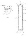
- FIG. 1 shows a schematic diagram of a floor panel 1 of a laminate or parquet floor.
- a floor panel 1 has a rectangular shape in plan view with two longitudinal edges 2, 4 and two shorter transverse edges 6, 8.
- a spring 12 for glueless connection of two floor panels along the longitudinal edge 2 is a spring 12 and along the longitudinal edge 4 a groove 10 with extended lower lip eleventh trained, as they are known for example from the prior art described above.
- tongue and groove joints are designed with horizontal locking systems, as they are known for example from the prior art described above. These locking systems can be engaged with each other either by planar shifting.
- each a groove 14 and a spring 16 are executed.
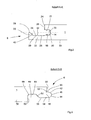
- the profiling of the two transverse edges 6, 8 is based on the FIGS. 2 and 3 explains the cuts along the lines AA and BB in FIG. 1 demonstrate.
- the groove 14 which in the illustrated embodiment, inwardly, ie, to the right in FIG. 2 opens easily.
- an upper groove surface 17 is slightly adjusted to the horizontal.
- a lower groove surface is formed with an approximately horizontally extending groove surface 18 and a Nutschräg Structure 20 adjacent to the groove bottom.
- the two last-mentioned surfaces 18, 20 are provided on an elongated groove under-cheek 22 extending in the horizontal direction (to the left in FIG FIG. 2 ) extends beyond a top beam 24.
- the upper beam 24 is limited by an end edge 26 frontally.
- a concave recess 28 is provided following the horizontal groove surface, which merges to the left, ie, the free end portion of the lower beam 22 in a locking projection 30 which is designed with a comparatively short in this embodiment locking surface 32, the is made oblique to the horizontal.
- the locking projection 30 then drops along its rear face 34 towards a guide projection 36 that extends vertically beyond the locking projection 30.
- a vertical extension of the guide projection 36 bounding top 38 is closer to the upper groove surface 16 than the horizontal groove surface 18.
- the top 38 passes over an obliquely downward sloping guide surface 40 in the back 34 of the locking projection 30 via.
- the locking projection 30 is arranged below the groove plane 18 containing the horizontal plane.
- transverse edge 6 of the floor panel 1 is carried out according to the spring 16
- the end portion in the illustration according to FIG. 3 is conical.
- This conification is effected by an upper spring inclined surface 42 and a slightly convex spring surface 44.
- the spring 16 is provided with a rounding 46.
- the spring inclined surface 42 merges into a spring upper side 48, which slopes slightly downwards towards the horizontal, and extends approximately as far as a spring-side end edge 50.
- a bevel chamfer 52 is milled.
- the slightly convex executed spring surface 44 merges into a horizontally extending spring underside 54, to which a slightly inclined to the horizontal salaried surface 56 connects to the left, which extends at a horizontal distance to a bottom 58 of the floor panel 1.
- This surface 56 extends practically from the predetermined by the spring-side end face 50 parting line inwardly up to a locking recess 60.
- the left end portion of the locking recess 60 is formed by a vertical surface 66, which merges via a transition radius 68 in the recess surface 64.
- the recess surface 64 extends approximately in the horizontal plane, in which also runs through the rounded 46 tip of the spring 16.
- the panels 1, 1 'seen in the longitudinal direction may be slightly curved, so that it may come in the transverse edge region when bending an open panel in the direction of the already laid panel to damage, since the transverse edges 6, 8 do not run parallel, but form an acute angle to each other.
- the distance between the transverse edges 6, 8 decreases towards the publisher, so that the transverse edge portions facing it collide on bending and thus the Good edge is damaged.
- the spring 16 extends to the transverse edge 6 of the panel 1 to be laid in the region adjacent to the longitudinal edge 2 to a stop region 78, said extension L is only a few 1/10 millimeters, for example, less than 0.5 cm.
- the width B of this extended contact area 78 in the illustrated embodiment is about 1 cm.
- FIGS. 2, 3 and 4 illustrated tongue and groove connection will be explained with reference to a laying operation. It is assumed that already some floor panels are laid and now another floor panel 1 should be attached to the already laid floor panels. For this purpose, the floor panel 1 to be laid along its longitudinal edge-for example, the longitudinal edge 12 -is connected to the already installed panel 1 ', this being done by planar displacement. For connecting the two adjacent transverse edges is according to FIG.
- transverse edge 8 of the floor panel 1 to be laid a slap block and the floor panel 1 by means of a hammer in the horizontal direction (arrow in FIG. 5b ), so that the spring 16 dips into the groove 14 and the system between the two approximately parallel surfaces 62, 40 is repealed.
- the gap S closes until the two end edges 26, 50 of the two panels 1, 1 'abut each other and the spring 16 is completely immersed in the groove 14, in which case the rounding 46 and the end face of the stop portion 78 still at a distance from the groove bottom 70 extends.
- the spring 16 lies along the surfaces 48 and 54 on the groove surfaces 16 and 18 and the inclined locking surface 32 engages behind the abutment surface 62 of the locking recess 60, so that the transverse edges 6, 8 are locked in horizontal and vertical directions.
- the guide projection 36 In this locking position of the guide projection 36 is completely received in the locking recess 62, wherein the guide surface 40 is formed in a gap S corresponding distance to the contact surface 62.
- the upper side 38 of the guide projection 36 extends at a distance from the recess surface 64.
- a stopper portion 78 is formed on the executed with a spring 16 transverse edge 6, which in turn is formed as a projection on the spring 16.
- a groove 74 is formed, which covers the locking projection 30 of the already laid panel 1 'when lowering the panel to be laid 1 in the intermediate position.
- the panel 1 to be laid is shown in a position shortly before reaching the above-described intermediate position.
- Another advantage is that the spring 16 of the panel 1 to be laid in the vertical direction is much better aligned with respect to the groove 14 of the already laid panel 1 ', so that the front-milled spring inclined surface 42 when moving from the intermediate position to the locking position only supports and not - as in the embodiment described above - serves as a guide element.
- the groove 74 is then in the area defined by the recess 28, in which case an enlarged chamber 76 is created in which any impurities or the like can accumulate without the pull-out forces are reduced.
- the transverse edges 8 are each designed with a guide projection 36.
- guide projections and the variants otherwise disclosed can also be provided on the longitudinal edges 11.
- the above-described stop area 78 can in principle be provided for all tongue and groove joints with and without horizontal latches and for all panel materials (laminate, parquet, etc.).
- connection for floor panels having along their longitudinal or transverse edges a tongue and groove connection and a horizontal lock.
- a guide projection is formed, along which two floor panels to be joined together can be pre-adjusted in the horizontal direction in an intermediate position.
Landscapes
- Engineering & Computer Science (AREA)
- Architecture (AREA)
- Civil Engineering (AREA)
- Structural Engineering (AREA)
- Floor Finish (AREA)
Claims (15)
- Raccord pour panneaux de plancher qui présentent des arêtes longitudinales et transversales (2, 4, 6, 8), une liaison à languette et rainure (14, 16) pour la fixation verticale étant réalisée le long d'au mois deux arêtes (2, 4, 6, 8) à raccorder de deux panneaux (1, 1'), une joue (22) de la rainure (14) étant prolongée au-delà de l'autre joue de rainure (24) vers l'autre panneau (1) et un verrouillage horizontal (32, 62) étant réalisé, lequel peut être amené en engagement de verrouillage par poussée planaire l'un vers l'autre des panneaux de plancher (1, 1'), une saillie de verrouillage (30) sur l'un des panneaux (1, 1') venant en prise à l'état verrouillé derrière une surface d'appui (62) d'un évidement de verrouillage (60) sur l'autre panneau (1, 1'), caractérisé en ce qu'une saillie de guidage (36) pénétrant à l'état encore non verrouillé dans un évidement de guidage (60) est réalisée à distance du verrouillage horizontal (30), le long de laquelle les deux panneaux (1, 1') sont préajustés dans le sens horizontal dans une position intermédiaire, la languette (16) ne pénétrant pas en position intermédiaire dans la rainure.
- Raccord selon la revendication 1, la languette (16) étant réalisée de manière conique le long d'une section d'extrémité.
- Raccord selon l'une quelconque des revendications précédentes, la saillie de verrouillage (30) étant disposée sur la joue inférieure (22) prolongée d'un panneau (1, 1') et l'évidement de verrouillage (60) étant disposé sur un côté inférieur de languette contigu de l'autre panneau (1, 1').
- Raccord selon la revendication 3, l'évidement de verrouillage (60) agissant aussi comme un évidement de guidage.
- Raccord selon l'une quelconque des revendications précédentes, la surface d'appui (62) de l'évidement de verrouillage (60) s'étendant à peu près parallèlement à une surface de guidage (40) de la saillie de guidage (36).
- Raccord selon l'une quelconque des revendications précédentes, la saillie de verrouillage (30) se trouvant sous un plan horizontal contenant une surface de rainure inférieure (18).
- Raccord selon l'une quelconque des revendications précédentes, un évidement (74) qui dépasse la saillie de verrouillage (30) dans la position intermédiaire étant réalisé sur le côté inférieur (54) de la languette (12).
- Raccord selon la revendication 7, l'évidement étant une moulure creuse (74).
- Raccord selon l'une quelconque des revendications précédentes, la zone (34, 40) disposée entre la saillie de verrouillage (30) et la saillie de guidage (36) de la joue de rainure prolongée (22) présentant une épaisseur supérieure à celle de la zone (28) disposée de l'autre côté de la saillie de verrouillage (30) de la joue de rainure (22).
- Raccord selon l'une quelconque des revendications précédentes, l'arête transversale (6) pourvue d'une languette (12) étant prolongée dans le sens de l'arête longitudinale par section vers une zone de butée (78).
- Raccord selon la revendication 10, la zone de butée (78) étant prolongée par rapport à l'autre partie de l'arête transversale (6) de moins de 0,5 mm et la largeur (B) de la zone de butée (78) s'élevant transversalement à l'arête longitudinale (2) à plus de 0,5 cm, de préférence à environ 1 cm.
- Raccord selon l'une quelconque des revendications précédentes, les deux panneaux de plancher (1, 1') pouvant être amenés par un déplacement à peu près planaire de la position intermédiaire à la position de verrouillage.
- Raccord selon la revendication 12, la course de déplacement (S) s'élevant à peu près à 1 mm.
- Raccord selon l'une quelconque des revendications précédentes, celui-ci étant réalisé sur les côtés transversaux (6, 8) des panneaux de plancher (1, 1').
- Raccord selon l'une quelconque des revendications précédentes, les panneaux de plancher (1, 1') étant fabriqués sensiblement en HDF/MDF.
Applications Claiming Priority (4)
| Application Number | Priority Date | Filing Date | Title |
|---|---|---|---|
| DE102007048037 | 2007-10-05 | ||
| DE102007058646 | 2007-12-04 | ||
| DE102008013551A DE102008013551A1 (de) | 2007-10-05 | 2008-03-11 | Verbindung für Fußbodenpaneele |
| PCT/DE2008/001601 WO2009043336A1 (fr) | 2007-10-05 | 2008-10-06 | Système d'assemblage pour lames de plancher |
Publications (2)
| Publication Number | Publication Date |
|---|---|
| EP2191083A1 EP2191083A1 (fr) | 2010-06-02 |
| EP2191083B1 true EP2191083B1 (fr) | 2013-04-10 |
Family
ID=40435587
Family Applications (2)
| Application Number | Title | Priority Date | Filing Date |
|---|---|---|---|
| EP08835056.6A Not-in-force EP2191083B1 (fr) | 2007-10-05 | 2008-10-06 | Raccord pour panneaux de plancher |
| EP08836515A Withdrawn EP2181228A1 (fr) | 2007-10-05 | 2008-10-06 | Système d'assemblage pour lames de plancher |
Family Applications After (1)
| Application Number | Title | Priority Date | Filing Date |
|---|---|---|---|
| EP08836515A Withdrawn EP2181228A1 (fr) | 2007-10-05 | 2008-10-06 | Système d'assemblage pour lames de plancher |
Country Status (3)
| Country | Link |
|---|---|
| EP (2) | EP2191083B1 (fr) |
| DE (2) | DE102007062106B4 (fr) |
| WO (2) | WO2009043336A1 (fr) |
Families Citing this family (2)
| Publication number | Priority date | Publication date | Assignee | Title |
|---|---|---|---|---|
| DE102009058666A1 (de) | 2008-12-16 | 2010-09-30 | Hamberger Industriewerke Gmbh | Fußbodenbelag |
| CN111779223B (zh) * | 2020-08-05 | 2026-04-10 | 上海兴邺材料科技有限公司 | 地板系统和竖直拆装式地板扣 |
Family Cites Families (21)
| Publication number | Priority date | Publication date | Assignee | Title |
|---|---|---|---|---|
| SE405697B (sv) * | 1975-06-12 | 1978-12-27 | Pettersson Ingvar | Monteringsdistans i notspont |
| DE2901633C2 (de) * | 1979-01-17 | 1985-04-04 | Johann 8949 Unterrieden Jakob | Profilbrett für eine feuchtigkeitsbelastete Holzbekleidung |
| JPH0811075B2 (ja) | 1982-06-30 | 1996-02-07 | 雄治 松岡 | 単クローン性抗cea抗体 |
| FR2568163B3 (fr) * | 1984-07-26 | 1986-08-08 | Clostyl | Panneau constitue de lames de bois a languette et rainure d'assemblage |
| SE501014C2 (sv) * | 1993-05-10 | 1994-10-17 | Tony Pervan | Fog för tunna flytande hårda golv |
| BE1010487A6 (nl) | 1996-06-11 | 1998-10-06 | Unilin Beheer Bv | Vloerbekleding bestaande uit harde vloerpanelen en werkwijze voor het vervaardigen van dergelijke vloerpanelen. |
| FR2785633B1 (fr) * | 1998-11-09 | 2001-02-09 | Valerie Roy | Panneau de recouvrement pour parquet, lambris ou analogue |
| DE19962830C2 (de) | 1999-12-23 | 2002-07-18 | Hamberger Industriewerke Gmbh | Verbindung |
| SE517183C2 (sv) | 2000-01-24 | 2002-04-23 | Valinge Aluminium Ab | Låssystem för mekanisk hopfogning av golvskivor, golvskiva försedd med låssystemet och metod för framställning av sådana golvskivor |
| DE20017461U1 (de) * | 2000-02-23 | 2001-02-15 | Kronotec Ag, Luzern | Fussbodenpaneel |
| EP1167653B1 (fr) * | 2000-06-30 | 2004-09-08 | Kronotec Ag | Procédé de pose de panneaux de sol |
| FR2825397B1 (fr) * | 2001-06-01 | 2004-10-22 | Tarkett Sommer Sa | Element(s) de revetement de sol a joint d'etancheite |
| DE20112474U1 (de) | 2001-07-28 | 2002-12-19 | M. Kaindl, Wals | Paneel, beispielsweise für Fußboden-, Wand- und/oder Deckenverkleidungen |
| DE10159284B4 (de) * | 2001-12-04 | 2005-04-21 | Kronotec Ag | Gebäudeplatte, insbesondere Bodenpaneel |
| DE20203311U1 (de) * | 2002-03-01 | 2002-05-08 | hülsta-werke Hüls GmbH & Co. KG, 48703 Stadtlohn | Paneelelement |
| DE10313112B4 (de) * | 2003-03-24 | 2007-05-03 | Fritz Egger Gmbh & Co. | Belag mit einer Mehrzahl von Paneelen, insbesondere Fußbodenbelag, sowie Verfahren zum Verlegen von Paneelen |
| DE102005002297A1 (de) | 2004-01-16 | 2005-08-04 | Hamberger Industriewerke Gmbh | Verbindung für plattenförmige Bauelemente, insbesondere für Fußbodenpaneele |
| DE102004028757B4 (de) * | 2004-04-02 | 2007-11-15 | hülsta-werke Hüls GmbH & Co. KG. | Paneelelement zur Boden-, Wand- und/oder Deckenverlegung sowie Verfahren zum Verlegen eines Belages, insbesondere eines Boden-, Wand- und/oder Deckenbelages |
| KR100687592B1 (ko) | 2004-04-30 | 2007-02-27 | 주식회사 한솔홈데코 | 조립식 바닥재 |
| JP4324140B2 (ja) * | 2005-08-15 | 2009-09-02 | 株式会社コトブキ | 板状パネル |
| DE102006024184A1 (de) * | 2006-05-23 | 2007-11-29 | Hipper, August, Dipl.-Ing. (FH) | Verbindung für Plattenpaneele |
-
2007
- 2007-12-21 DE DE102007062106A patent/DE102007062106B4/de not_active Expired - Fee Related
-
2008
- 2008-03-11 DE DE102008013551A patent/DE102008013551A1/de not_active Withdrawn
- 2008-10-06 EP EP08835056.6A patent/EP2191083B1/fr not_active Not-in-force
- 2008-10-06 WO PCT/DE2008/001601 patent/WO2009043336A1/fr not_active Ceased
- 2008-10-06 WO PCT/DE2008/001607 patent/WO2009043339A1/fr not_active Ceased
- 2008-10-06 EP EP08836515A patent/EP2181228A1/fr not_active Withdrawn
Also Published As
| Publication number | Publication date |
|---|---|
| EP2181228A1 (fr) | 2010-05-05 |
| EP2191083A1 (fr) | 2010-06-02 |
| DE102008013551A1 (de) | 2009-04-16 |
| DE102007062106A1 (de) | 2009-04-23 |
| WO2009043336A1 (fr) | 2009-04-09 |
| DE102007062106B4 (de) | 2013-04-04 |
| WO2009043339A1 (fr) | 2009-04-09 |
Similar Documents
| Publication | Publication Date | Title |
|---|---|---|
| DE102009034903B3 (de) | Belag aus mechanisch miteinander verbindbaren Paneelen | |
| EP2226447B1 (fr) | Panneau, en particulier panneau de sol | |
| EP2057327B1 (fr) | Panneau, notamment panneau de sol | |
| EP3581732B1 (fr) | Panneau avec rainure et baguette étanchéifiante | |
| AT410815B (de) | Verbindung von plattenförmigen bauteilen | |
| EP3877610B1 (fr) | Panneau | |
| DE102004001363A1 (de) | Verbindung für Fußbodenelemente | |
| EP1380710B1 (fr) | Panneau de plancher et méthode d'installation d'un panneau de plancher | |
| WO2001051733A1 (fr) | Element lambrisse | |
| DE102006024184A1 (de) | Verbindung für Plattenpaneele | |
| DE102006057491A1 (de) | Paneel sowie Bodenbelag | |
| WO2008083662A1 (fr) | Panneau et revêtement de sol | |
| EP1900889A2 (fr) | Panneau de plancher | |
| DE102007019786B4 (de) | Verbindung für plattenförmige Bauelemente | |
| DE10224540B4 (de) | Fussbodenpaneel | |
| DE202007000310U1 (de) | Paneel sowie Bodenbelag | |
| DE20000484U1 (de) | Fußbodenbelag aus Paneelelementen | |
| DE10242647B4 (de) | Paneel | |
| EP2191083B1 (fr) | Raccord pour panneaux de plancher | |
| DE102008003117B4 (de) | Einrichtung zum Verriegeln zweier Bauplatten | |
| DE10038662A1 (de) | Verbindung | |
| DE102007030750B4 (de) | Verbindung | |
| EP3080365B1 (fr) | Panneau pourvu d'un élément de verrouillage | |
| EP2754810B1 (fr) | Paroi de séparation | |
| DE102007046598B4 (de) | Paneel |
Legal Events
| Date | Code | Title | Description |
|---|---|---|---|
| PUAI | Public reference made under article 153(3) epc to a published international application that has entered the european phase |
Free format text: ORIGINAL CODE: 0009012 |
|
| 17P | Request for examination filed |
Effective date: 20100224 |
|
| AK | Designated contracting states |
Kind code of ref document: A1 Designated state(s): AT BE BG CH CY CZ DE DK EE ES FI FR GB GR HR HU IE IS IT LI LT LU LV MC MT NL NO PL PT RO SE SI SK TR |
|
| AX | Request for extension of the european patent |
Extension state: AL BA MK RS |
|
| 17Q | First examination report despatched |
Effective date: 20100819 |
|
| DAX | Request for extension of the european patent (deleted) | ||
| GRAP | Despatch of communication of intention to grant a patent |
Free format text: ORIGINAL CODE: EPIDOSNIGR1 |
|
| GRAS | Grant fee paid |
Free format text: ORIGINAL CODE: EPIDOSNIGR3 |
|
| GRAA | (expected) grant |
Free format text: ORIGINAL CODE: 0009210 |
|
| AK | Designated contracting states |
Kind code of ref document: B1 Designated state(s): AT BE BG CH CY CZ DE DK EE ES FI FR GB GR HR HU IE IS IT LI LT LU LV MC MT NL NO PL PT RO SE SI SK TR |
|
| REG | Reference to a national code |
Ref country code: GB Ref legal event code: FG4D Free format text: NOT ENGLISH |
|
| REG | Reference to a national code |
Ref country code: AT Ref legal event code: REF Ref document number: 606125 Country of ref document: AT Kind code of ref document: T Effective date: 20130415 Ref country code: CH Ref legal event code: EP |
|
| REG | Reference to a national code |
Ref country code: IE Ref legal event code: FG4D Free format text: LANGUAGE OF EP DOCUMENT: GERMAN |
|
| REG | Reference to a national code |
Ref country code: DE Ref legal event code: R096 Ref document number: 502008009700 Country of ref document: DE Effective date: 20130606 |
|
| PG25 | Lapsed in a contracting state [announced via postgrant information from national office to epo] |
Ref country code: SI Free format text: LAPSE BECAUSE OF FAILURE TO SUBMIT A TRANSLATION OF THE DESCRIPTION OR TO PAY THE FEE WITHIN THE PRESCRIBED TIME-LIMIT Effective date: 20130410 |
|
| REG | Reference to a national code |
Ref country code: NL Ref legal event code: VDEP Effective date: 20130410 Ref country code: LT Ref legal event code: MG4D |
|
| PG25 | Lapsed in a contracting state [announced via postgrant information from national office to epo] |
Ref country code: LT Free format text: LAPSE BECAUSE OF FAILURE TO SUBMIT A TRANSLATION OF THE DESCRIPTION OR TO PAY THE FEE WITHIN THE PRESCRIBED TIME-LIMIT Effective date: 20130410 Ref country code: PT Free format text: LAPSE BECAUSE OF FAILURE TO SUBMIT A TRANSLATION OF THE DESCRIPTION OR TO PAY THE FEE WITHIN THE PRESCRIBED TIME-LIMIT Effective date: 20130812 Ref country code: FI Free format text: LAPSE BECAUSE OF FAILURE TO SUBMIT A TRANSLATION OF THE DESCRIPTION OR TO PAY THE FEE WITHIN THE PRESCRIBED TIME-LIMIT Effective date: 20130410 Ref country code: SE Free format text: LAPSE BECAUSE OF FAILURE TO SUBMIT A TRANSLATION OF THE DESCRIPTION OR TO PAY THE FEE WITHIN THE PRESCRIBED TIME-LIMIT Effective date: 20130410 Ref country code: ES Free format text: LAPSE BECAUSE OF FAILURE TO SUBMIT A TRANSLATION OF THE DESCRIPTION OR TO PAY THE FEE WITHIN THE PRESCRIBED TIME-LIMIT Effective date: 20130721 Ref country code: GR Free format text: LAPSE BECAUSE OF FAILURE TO SUBMIT A TRANSLATION OF THE DESCRIPTION OR TO PAY THE FEE WITHIN THE PRESCRIBED TIME-LIMIT Effective date: 20130711 Ref country code: IS Free format text: LAPSE BECAUSE OF FAILURE TO SUBMIT A TRANSLATION OF THE DESCRIPTION OR TO PAY THE FEE WITHIN THE PRESCRIBED TIME-LIMIT Effective date: 20130810 Ref country code: NO Free format text: LAPSE BECAUSE OF FAILURE TO SUBMIT A TRANSLATION OF THE DESCRIPTION OR TO PAY THE FEE WITHIN THE PRESCRIBED TIME-LIMIT Effective date: 20130710 Ref country code: NL Free format text: LAPSE BECAUSE OF FAILURE TO SUBMIT A TRANSLATION OF THE DESCRIPTION OR TO PAY THE FEE WITHIN THE PRESCRIBED TIME-LIMIT Effective date: 20130410 |
|
| PG25 | Lapsed in a contracting state [announced via postgrant information from national office to epo] |
Ref country code: PL Free format text: LAPSE BECAUSE OF FAILURE TO SUBMIT A TRANSLATION OF THE DESCRIPTION OR TO PAY THE FEE WITHIN THE PRESCRIBED TIME-LIMIT Effective date: 20130410 Ref country code: CY Free format text: LAPSE BECAUSE OF FAILURE TO SUBMIT A TRANSLATION OF THE DESCRIPTION OR TO PAY THE FEE WITHIN THE PRESCRIBED TIME-LIMIT Effective date: 20130410 Ref country code: HR Free format text: LAPSE BECAUSE OF FAILURE TO SUBMIT A TRANSLATION OF THE DESCRIPTION OR TO PAY THE FEE WITHIN THE PRESCRIBED TIME-LIMIT Effective date: 20130410 Ref country code: BG Free format text: LAPSE BECAUSE OF FAILURE TO SUBMIT A TRANSLATION OF THE DESCRIPTION OR TO PAY THE FEE WITHIN THE PRESCRIBED TIME-LIMIT Effective date: 20130710 Ref country code: LV Free format text: LAPSE BECAUSE OF FAILURE TO SUBMIT A TRANSLATION OF THE DESCRIPTION OR TO PAY THE FEE WITHIN THE PRESCRIBED TIME-LIMIT Effective date: 20130410 |
|
| PG25 | Lapsed in a contracting state [announced via postgrant information from national office to epo] |
Ref country code: SK Free format text: LAPSE BECAUSE OF FAILURE TO SUBMIT A TRANSLATION OF THE DESCRIPTION OR TO PAY THE FEE WITHIN THE PRESCRIBED TIME-LIMIT Effective date: 20130410 Ref country code: EE Free format text: LAPSE BECAUSE OF FAILURE TO SUBMIT A TRANSLATION OF THE DESCRIPTION OR TO PAY THE FEE WITHIN THE PRESCRIBED TIME-LIMIT Effective date: 20130410 Ref country code: DK Free format text: LAPSE BECAUSE OF FAILURE TO SUBMIT A TRANSLATION OF THE DESCRIPTION OR TO PAY THE FEE WITHIN THE PRESCRIBED TIME-LIMIT Effective date: 20130410 Ref country code: CZ Free format text: LAPSE BECAUSE OF FAILURE TO SUBMIT A TRANSLATION OF THE DESCRIPTION OR TO PAY THE FEE WITHIN THE PRESCRIBED TIME-LIMIT Effective date: 20130410 |
|
| PLBE | No opposition filed within time limit |
Free format text: ORIGINAL CODE: 0009261 |
|
| STAA | Information on the status of an ep patent application or granted ep patent |
Free format text: STATUS: NO OPPOSITION FILED WITHIN TIME LIMIT |
|
| PG25 | Lapsed in a contracting state [announced via postgrant information from national office to epo] |
Ref country code: IT Free format text: LAPSE BECAUSE OF FAILURE TO SUBMIT A TRANSLATION OF THE DESCRIPTION OR TO PAY THE FEE WITHIN THE PRESCRIBED TIME-LIMIT Effective date: 20130410 Ref country code: RO Free format text: LAPSE BECAUSE OF FAILURE TO SUBMIT A TRANSLATION OF THE DESCRIPTION OR TO PAY THE FEE WITHIN THE PRESCRIBED TIME-LIMIT Effective date: 20130410 |
|
| 26N | No opposition filed |
Effective date: 20140113 |
|
| REG | Reference to a national code |
Ref country code: DE Ref legal event code: R097 Ref document number: 502008009700 Country of ref document: DE Effective date: 20140113 |
|
| BERE | Be: lapsed |
Owner name: HAMBERGER INDUSTRIEWERKE G.M.B.H. Effective date: 20131031 |
|
| PG25 | Lapsed in a contracting state [announced via postgrant information from national office to epo] |
Ref country code: MC Free format text: LAPSE BECAUSE OF FAILURE TO SUBMIT A TRANSLATION OF THE DESCRIPTION OR TO PAY THE FEE WITHIN THE PRESCRIBED TIME-LIMIT Effective date: 20130410 |
|
| REG | Reference to a national code |
Ref country code: CH Ref legal event code: PL |
|
| GBPC | Gb: european patent ceased through non-payment of renewal fee |
Effective date: 20131006 |
|
| REG | Reference to a national code |
Ref country code: IE Ref legal event code: MM4A |
|
| PG25 | Lapsed in a contracting state [announced via postgrant information from national office to epo] |
Ref country code: CH Free format text: LAPSE BECAUSE OF NON-PAYMENT OF DUE FEES Effective date: 20131031 Ref country code: GB Free format text: LAPSE BECAUSE OF NON-PAYMENT OF DUE FEES Effective date: 20131006 Ref country code: LI Free format text: LAPSE BECAUSE OF NON-PAYMENT OF DUE FEES Effective date: 20131031 |
|
| REG | Reference to a national code |
Ref country code: FR Ref legal event code: ST Effective date: 20140630 |
|
| PG25 | Lapsed in a contracting state [announced via postgrant information from national office to epo] |
Ref country code: FR Free format text: LAPSE BECAUSE OF NON-PAYMENT OF DUE FEES Effective date: 20131031 |
|
| PG25 | Lapsed in a contracting state [announced via postgrant information from national office to epo] |
Ref country code: BE Free format text: LAPSE BECAUSE OF NON-PAYMENT OF DUE FEES Effective date: 20131031 |
|
| PG25 | Lapsed in a contracting state [announced via postgrant information from national office to epo] |
Ref country code: IE Free format text: LAPSE BECAUSE OF NON-PAYMENT OF DUE FEES Effective date: 20131006 |
|
| REG | Reference to a national code |
Ref country code: AT Ref legal event code: MM01 Ref document number: 606125 Country of ref document: AT Kind code of ref document: T Effective date: 20131006 |
|
| PG25 | Lapsed in a contracting state [announced via postgrant information from national office to epo] |
Ref country code: AT Free format text: LAPSE BECAUSE OF NON-PAYMENT OF DUE FEES Effective date: 20131006 |
|
| PG25 | Lapsed in a contracting state [announced via postgrant information from national office to epo] |
Ref country code: TR Free format text: LAPSE BECAUSE OF FAILURE TO SUBMIT A TRANSLATION OF THE DESCRIPTION OR TO PAY THE FEE WITHIN THE PRESCRIBED TIME-LIMIT Effective date: 20130410 |
|
| PG25 | Lapsed in a contracting state [announced via postgrant information from national office to epo] |
Ref country code: HU Free format text: LAPSE BECAUSE OF FAILURE TO SUBMIT A TRANSLATION OF THE DESCRIPTION OR TO PAY THE FEE WITHIN THE PRESCRIBED TIME-LIMIT; INVALID AB INITIO Effective date: 20081006 Ref country code: LU Free format text: LAPSE BECAUSE OF NON-PAYMENT OF DUE FEES Effective date: 20131006 |
|
| PG25 | Lapsed in a contracting state [announced via postgrant information from national office to epo] |
Ref country code: MT Free format text: LAPSE BECAUSE OF FAILURE TO SUBMIT A TRANSLATION OF THE DESCRIPTION OR TO PAY THE FEE WITHIN THE PRESCRIBED TIME-LIMIT Effective date: 20130410 |
|
| REG | Reference to a national code |
Ref country code: DE Ref legal event code: R082 Ref document number: 502008009700 Country of ref document: DE Representative=s name: WINTER, BRANDL - PARTNERSCHAFT MBB, PATENTANWA, DE Ref country code: DE Ref legal event code: R082 Ref document number: 502008009700 Country of ref document: DE Representative=s name: WINTER, BRANDL, FUERNISS, HUEBNER, ROESS, KAIS, DE |
|
| PGFP | Annual fee paid to national office [announced via postgrant information from national office to epo] |
Ref country code: DE Payment date: 20220830 Year of fee payment: 15 |
|
| REG | Reference to a national code |
Ref country code: DE Ref legal event code: R119 Ref document number: 502008009700 Country of ref document: DE |
|
| PG25 | Lapsed in a contracting state [announced via postgrant information from national office to epo] |
Ref country code: DE Free format text: LAPSE BECAUSE OF NON-PAYMENT OF DUE FEES Effective date: 20240501 |