EP2191924A1 - Kreissägeblatt - Google Patents
Kreissägeblatt Download PDFInfo
- Publication number
- EP2191924A1 EP2191924A1 EP09176399A EP09176399A EP2191924A1 EP 2191924 A1 EP2191924 A1 EP 2191924A1 EP 09176399 A EP09176399 A EP 09176399A EP 09176399 A EP09176399 A EP 09176399A EP 2191924 A1 EP2191924 A1 EP 2191924A1
- Authority
- EP
- European Patent Office
- Prior art keywords
- fixing ring
- saw blade
- ring
- notches
- abrasive
- Prior art date
- Legal status (The legal status is an assumption and is not a legal conclusion. Google has not performed a legal analysis and makes no representation as to the accuracy of the status listed.)
- Granted
Links
Images



Classifications
-
- B—PERFORMING OPERATIONS; TRANSPORTING
- B23—MACHINE TOOLS; METAL-WORKING NOT OTHERWISE PROVIDED FOR
- B23D—PLANING; SLOTTING; SHEARING; BROACHING; SAWING; FILING; SCRAPING; LIKE OPERATIONS FOR WORKING METAL BY REMOVING MATERIAL, NOT OTHERWISE PROVIDED FOR
- B23D61/00—Tools for sawing machines or sawing devices; Clamping devices for these tools
- B23D61/02—Circular saw blades
- B23D61/025—Details of saw blade body
- B23D61/026—Composite body, e.g. laminated
Definitions
- the present invention generally relates to a circular cutting tool for a sawing machine. More particularly, it relates to a circular saw blade with an abrasive ring as used for hot or cold cutting of metal profiles, in particular steel, special steel, alloy steel or cast iron.
- a large diameter saw blade designed according to the invention is particularly applicable to the hot or cold cutting blooms, billets, steel beams, round, rails and tubes at the output of rolling mill trains.
- Circular metal saw blades manufactured in one piece are known. Also known are one-piece saw blades of abrasive material.
- CN 101049645A a two-part circular saw blade composed of a metal support disc and a ring-shaped abrasive ring fixed around the periphery of the metal support disc.
- the support disk of the saw blade according to this document has on its periphery a fixing ring on which is fixed the abrasive ring.
- the attachment ring has a plurality of notches for securing the abrasive ring which extends radially beyond the support disk.
- the hooking notches have a trapezoidal shape in the plane of the support disk.
- the opening of the notches to the outside of the support disk represents the small base of a trapezium, i.e. that this opening constitutes an inlet port followed by a circumferential widening due to the trapezoidal shape of the notch.
- a saw blade for hot or cold cutting of metal profiles is typically subjected to significant stresses in use due to its large diameter and cutting speed. These constraints are even more pronounced in the case of an abrasive monobloc saw blade which typically undergoes greater efforts of at least 25% compared to the forces experienced by a metal monoblock saw blade under the same working conditions. Faced with such constraints, a saw blade as proposed in the document CN 101049645A thus presents a certain risk of stalling of the abrasive and a risk of fatigue, or even deterioration, of the fixing ring.
- the saw blades available have significant vibrations during use, especially at high cutting speeds. This results in the disadvantages of excessive wear of the abrasive and high cutting noise that lead to unpleasant working conditions.
- a saw blade according to the invention is stronger and therefore more reliable, particularly in the case of a large diameter saw blade used at speeds high cutting speeds for the hot or cold cutting of ferrous materials, especially steel products, special steel or alloy steel on rolling mills.
- a circular saw blade according to the present invention comprises, in a manner known per se, a metal support disc having on its periphery a fixing ring, in the form of a cylindrical ring for example in the form of a peripheral annular tongue, and an abrasive ring. , also in the form of a cylindrical ring, which is fixed on the fixing ring.
- the abrasive ring is typically made based on a curable binder, for example based on a thermosetting resin of bakelite type, comprising abrasive grains of a type known per se and zirconium embedded in the cured binder.
- a plurality of hooking notches in the fixing ring allows the abrasive ring to be attached to the support disc.
- each inlet orifice is an opening of the catching notch towards the outside of the fixing ring measuring, in circumference of the crown fixation, an arc length smaller than a maximum arc length measured by the hooking notch.
- said enlargement has a substantially rounded shape.
- a saw blade composed according to the present invention comprising an abrasive ring, in particular a zirconium abrasive ring, may have a total diameter of between 1000 mm and 2500 mm and is ready to be used on a sawing machine or on a machine.
- chainsaw for cutting hot, preferably up to 1000 ° C, or cold, preferably at room temperature, blooms, billets, rounds, beams or steel rails, for example at the exit of a rolling mill in the iron and steel industry.
- Said enlargement advantageously has a substantially circular shape.
- Circular hooking notches can be easily made by drilling.
- the enlargement is delimited by a circular segment having an opening angle greater than 180 °, i.e. a segment of a circle in the geometric sense of the term, whose area is greater than the semicircle and whose base of the circle segment is smaller than the diameter of that circle.
- the enlargement is delimited by a circular segment having an opening angle between 240 ° and 300 ° in order to obtain a very reliable fastening.
- said widening may be preceded by a funnel-shaped inlet orifice, i.e.
- an inlet opening a notch hooking outwardly of the fixing ring and forming a prolonged passage whose opening tapers towards the inside of the fixing ring.
- Such an inlet makes it possible to contribute to the fixing ring better supporting the stress forces experienced by the abrasive ring.
- the hooking notches have a diameter representing up to twice the width of the fixing ring, this diameter preferably being between 50% and 200%, and more preferably between 60% to 180% of the width of the attachment ring (ie the radial extent of this ring).
- the width of the fixing ring represents between 1% and 20% of the total diameter of the support disk.
- the fixing ring has a width which depends on the total diameter of the saw blade and is preferably between 40 mm and 80 mm. In other words, the fixing ring has an annular shape whose dimension in the radial direction is between 40 mm and 80 mm.
- the abrasive ring advantageously extends radially beyond the outer contour of the fastener ring so that the extension is between 125% and 875% of the width of the fastener ring.
- the said extension i.e. the width of the abrasive ring radially exceeding the outer contour of the fixing ring, can be between 100 mm and 350 mm depending on the total diameter of the blade.
- Such an extension of the abrasive ring beyond the outer contour of the fixing ring represents the useful part of abrasive material actually used for sawing or cutting.
- the hooking notches are arranged in the fixing ring so as to be circumferentially spaced in a substantially regular manner, i.e. that the hooking notches are located relative to one another along a circumference of the fastener ring in substantially regular spaced relation. More preferably, the hooking notches on the fixing ring are spaced at an angular spacing substantially equal to each other by an angle determined according to the diameter of the support disk. This angle is preferably between 12 ° and 24 ° with respect to the geometric center of the annular fixing ring which makes it possible to obtain an adequate number of hooking notches.
- the fixing ring advantageously has at least one through hole between at least one pair of fastening notches for the passage and attachment of reinforcing filaments.
- Such reinforcing filaments can be used to reinforce the thermosetting resin of the abrasive ring fixed on the fixing ring. More preferably, two through holes are located between each pair of hooking notches in substantially regular spaced relationship along a circumference of the fastener ring to provide balancing.
- the support disk has one or more lightening notches between at least one and preferably between each pair of hooking notches to lighten the fixing ring on the support disk.
- the additional lightening notches make it possible to lighten, together with notches of considerable size, the fixing ring while surprisingly improving the vibratory and acoustic behavior of the saw blade during use. It will be appreciated that such an improvement in the acoustic behavior of the saw blade furthermore makes it possible to reduce the cutting noise of the saw blade during use. For example, a noise reduction of more than 40 dB (decibel) has been measured in practice with respect to the noise of a metal one-piece circular saw blade under the same conditions of use.
- the fastener ring has a lightening notch between each pair of fastening notches.
- the relief notches can for example be obtained by cutting or milling.
- each lightening notch has a symmetry with respect to a generally diametrical plane, i.e. a plane which is perpendicular to the plane of the fixing ring and which is parallel to a diameter of the saw blade.
- each lightening notch has an isosceles triangle shape in the plane of the O-ring, i.e. a pointed form extending inwardly of the fixing ring whose edges formed by the fixing ring represent the sides of the same length.
- the fastener ring has a plurality of lightening notches formed such that the fastener ring has a profile which has no preferred orientation in the direction of rotation, i.e. that the saw blade can be used in both directions of operation.
- the fixing ring is thinned with respect to the support disk, preferably so that the fixing ring has a thinner thickness of at least 3 mm with respect to the thickness of the support disk.
- the fixing ring preferably has a thinner thickness of at least 3 mm with respect to the thickness of a central portion of the disk. of support. This difference in thickness is advantageously filled by the thickness of the abrasive ring which laterally covers the fixing ring on which it is fixed.
- the abrasive ring fills not only the above-mentioned thickness difference but has a greater thickness than the central portion of the metal support disk, so as to exceed in the transverse direction, preferably at least 2 to 3 mm, on each side of the center part of the support disc.
- This difference in thickness allows a cutting width which is wider than the thickness of the support disc and thus avoids friction of the metal support disc with a material to be cut in use.
- the support disk preferably has a diameter of between 400 mm and 2200 mm and a thickness of the part located inside the fixing ring which measures preferably between 5 mm and 15 mm.
- the metal support disk is advantageously made of a special steel chosen to resist without deformation at high temperatures between 200 ° C - 400 ° C.
- the finished saw blade has a total diameter of preferably between 800 mm and 2500 mm and a cutting width preferably between 7 mm and 25 mm. This size order makes it possible to use the saw blade for the hot or cold cutting of ferrous materials, in particular steel, special steel, alloy steel or cast iron, for example at the exit of railway trains. rolling mill.
- the fastener ring has on at least a portion of its outer contour a toothed profile having one or more teeth, i.e. one or more teeth which radially extend the fixing ring.
- the teeth are located between the inlet ports of the hooking notches, in the case where the fixing ring has notches of lightening of course between these notches of lightening.
- each tooth has symmetry with respect to a generally diametrical plane, i.e. a plane which is perpendicular to the plane of the fixing ring and which passes through a diameter of the saw blade.
- each tooth has an isosceles triangle shape, i.e. a pointed form extending outwardly of the fixing ring having sides of the same length.
- the fixing ring has a plurality of teeth formed such that the fixing ring has a profile which has no preferred orientation in either direction of rotation of the saw blade.
- a tooth adjacent to such an orifice may have a side that extends one side of the funnel-shaped orifice.
- a tooth near a lightening notch which has for example isosceles triangle shape, may have a side that extend the side of the lightening notches.
- the saw blade according to the invention is particularly suitable for sawing or cutting hot or cold ferrous materials, in particular steel, special steel (eg stainless steel), alloy steel, cast iron or non-ferrous materials, and more particularly for cutting hot or cold blooms, billets, beams, rounds, rails or steel tubes at the output of rolling mill trains in the iron and steel and processing industries metals.
- steel special steel (eg stainless steel), alloy steel, cast iron or non-ferrous materials, and more particularly for cutting hot or cold blooms, billets, beams, rounds, rails or steel tubes at the output of rolling mill trains in the iron and steel and processing industries metals.
- the FIG.1 represents an overall side view of a compound circular saw blade, i.e. in two parts according to the present invention.
- the saw blade 10 has a total diameter of between 800 mm and 2500 mm (in the plane of the FIG.1 ) and a cutting width of between 7 mm and 25 mm (in a plane perpendicular to that of the FIG.1 ), the exact dimensions being chosen according to the intended use, further depending on the size of the product to be cut.
- the saw blade 10 comprises a metal support disc 12 made of a special steel which has alloying elements to resist without deformation at high temperatures of between 200 ° C - 400 ° C.
- the support disc 12 is made from a steel sheet which is machined in the shape of a disc.
- the support disc 12 has on its periphery a fixing ring 14 with a plurality of attachment notches 16 created during the machining of the disc.
- Fastening ring means the region between two concentric cylinders at the end of the support disk 12.
- the fixing ring 14 is indicated by dark hatching at the FIG.2 .
- the hooking notches 16 allow the attachment of an abrasive ring 18 fixed on the fixing ring 14.
- the FIG.1 shows schematically the contour of the abrasive ring 18 in broken lines.
- the crown abrasive 18 is made of a thermosetting resin comprising abrasive grains and zirconium grains embedded in the polymerized resin.
- the support disc 12 further has a central bore 20 for mounting the support disc 12 on a drive mechanism (not shown) and diametrically opposed auxiliary eccentric drive holes 22 which can be used to mate said disc. support 12 to the drive mechanism.
- the support disc 12 also has handling holes 23 for handling the saw blade 10 without the risk of damage to the abrasive ring 18, for example during assembly or disassembly of the saw blade 10 on the drive mechanism.
- the support disc 12 itself may after machining have a diameter of between 400 mm and 2200 mm and a thickness of between 5 mm and 15 mm.
- the fixing ring 14 has a width representing between 1% and 20% of the total diameter of the support disk 12, typically a width of between 40 mm and 80 mm.
- the hooking notches 16 have a circular shape, more particularly a circular segment shape 24 having an opening angle greater than 180 ° (degrees of arc), preferably an opening angle of 240 ° to 300 ° .
- the hooking notches 16 have a maximum diameter of up to about twice the width of the fixing ring 14, preferably between 60% to 180% of the width of the fixing ring 14. These notches 16 are located on the fixing ring 14 in regular spaced circumferential relation at an angle of between 12 ° and 24 °, for example 15 ° degrees of angle, with respect to the center of the support disc 12. Angle and thus the number of hooking notches 16 is determined according to the diameter of the support disc 12.
- the hooking notches 16 can be created by cutting, milling or by simple drilling.
- the through holes 28 allow the passage and the attachment of reinforcing filaments and also help to lighten the support disk 12.
- the relief notches 26 contribute to the support of the forces of stress exerted on the abrasive ring 18 when sawing.
- the lightening notches 26 have an isosceles triangular shape so as not to give a preferential direction to the profile of the fixing ring 14 in the clockwise or counter-clockwise direction.
- the lightening notches 26 are also in regular spaced relationship, for example 15 ° degrees angle relative to the center of the support disk 12.
- the additional recesses or voids formed in the fixing ring 14 by the notches 26 and lightening holes 28, in addition to those formed by the attachment notches 16, contribute to the reliable attachment of abrasive ring 18.
- the metal volume that remains after creation of these recesses by machining in the region delimited by the lower radius and the upper radius of the fixing ring 14 is of the order of 55% to 65% of the initial volume of the support disk 12 in this region, the volume of metal removed by machining being determined according to the diameter of the support disk 12.
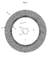
- the FIG.2 shows in side view a circular saw blade 10 according to the FIG.1 in the completed state and schematically shows the abrasive ring 18 fixed on the fixing ring 14.
- the abrasive ring 18 comprises a first portion of the abrasive ring 30 which laterally covers the fixing ring 14 and a second portion of the abrasive ring 32 which extends radially sawing the circular saw blade 10 beyond the fixing ring 14.
- the first part 30 represents the part of the abrasive for fixing on the fixing ring 14.
- the second part 32 forms an extension of length between 100 mm and 350 mm and represents the useful part of the abrasive.
- FIG.3 is a partial side view of the fixing ring 10 of the support disc 12 according to a first embodiment which corresponds to that shown in FIG. FIG.1 .
- Each hooking notch 16 has a circular segment shape 24 having an opening angle greater than 180 °, preferably an opening angle of 240 ° to 300 °.
- the reference 34 indicates the base of the circular segment 24. This base therefore has a length smaller than a diameter of the latching notch 16, in other words, an arc length less than the maximum arc length of the arc. evidently formed by the hooking notch 16.
- Each hooking notch 16 has a diameter representing up to twice the width of the fastener ring 14, preferably between 60% to 180% of the width of the crown fixing 14 to ensure a reliable attachment of the abrasive.
- Forms of the lightening notch 26 other than an isosceles triangle which also admit symmetry with respect to a diametrical plane bisecting between two hooking notches 16 are also conceivable.
- FIG.4 is a partial side view of another embodiment of a fastener ring 214 on a support disc 12 similar to that of Fig.1-3 .
- the fixing ring 214 according to this second embodiment has on its outer contour, between the inlet openings 36 of the hooking notches 16 and the lightening notches 26, a toothed profile 238 with a a plurality of teeth 240 in the form of isosceles triangles which radially extend the fixing ring 214.
- Each tooth 240 has a symmetry with respect to a plane which is perpendicular to the plane of the fixing ring 214 and which is substantially parallel to a diameter of the saw blade 10, i.e.
- teeth 240 are of small size compared to the fastening notches 16 and the notches of relief 26 but contribute to improve the attachment of the abrasive and the support of the tangential forces exerted on the abrasive ring 18.
- the teeth 240 of the toothed profile 238 on the fastening ring 214 are in the form of an isosceles triangle which radially extend the fixing ring 14.
- the teeth 240 adjacent to a catch notch 16 which has a funnel-shaped inlet orifice 36 have a tooth side which extends the contour of the inlet port 36.
- the tooth profile 238 may be created on the support disc 12 by suitable machining, eg by milling, cutting or punching. .
- FIG.5 is a partial side view of a third embodiment of a fixing ring 314 on a support disc 12 similar to that of the Fig.1-3 .
- each attachment notch 16 has on the outer contour of the fixing ring 14 an inlet 336 of particular design, namely funnel-shaped followed by an enlargement 24 in the circumferential direction of the fixing ring 14.
- the widening 24 forming a circular segment having an opening angle greater than 180 °.
- each funnel-shaped inlet orifice 336 can be obtained by cutting or milling, and contribute to the support of the tangential forces exerted on the abrasive ring 18. It will be appreciated that a tooth profile of outer contour of the fixing ring according to the FIG.4 may also be provided on the outer contour of the fixing ring 14, 314 according to the embodiments shown in FIG. FIG.5 and the FIG.1 .
- FIG.6 represents a partial view of a radial section of the circular saw blade 10 detailing the profile of the fastening ring 14 in the form of thinned peripheral tongue.
- the fixing ring 14 is thinned at least 3 mm with respect to the thickness of a central portion of the support disk 12 by rough machining giving a rough surface to the fixing ring 14 which contributes to the attachment of the abrasive ring 18, in particular leaving ridges at the transitional shelf between the flat face of the support disc 12 and the flat portion of the fixing ring 14.
- the central portion of the support disc 12 has a thickness between 5 mm and 15 mm.
- FIG.7 represents a partial view of a radial section of the circular saw blade as at FIG.6 detailing the profile of the abrasive ring 18 fixed on the fixing ring 14.
- the abrasive ring 18 has a thickness of between 7 mm and 25 mm, preferably a thickness wider than the thickness of a central portion of the support disk 12 so as to project axially on each side by at least 2 to 3 mm. This difference in thickness allows a cutting width of the saw blade 10 wider than the thickness of the support disk 12 in order to avoid significant friction of the lateral portions of the metal support disc 12 with a material to be cut at the same time. use of the saw blade 10.
- a saw blade according to one of the preferred embodiments shown in FIGS. FIG.1 to FIG.7 may be manufactured by the following manufacturing steps: provision of a metal blank, eg in the form of a special high-temperature steel sheet; creating a central bore 20; piercing eccentric drive holes 22 and handling holes 23; placing the blank round by radial machining of the outer periphery; creating a thinned tongue serving as a base for a fixing ring 14, 214, 314 by decreasing the axial thickness of the peripheral region by means of a type of machining known per se, eg by milling; creation of hooking notches 16 of rounded shape, creation of relief notches 26 and through holes 28 by appropriate machining, eg cutting, milling, drilling or punching in order to produce the fixing ring 14, 214, 314; optionally machining funnel entry ports 236 and / or toothed profiles 238; then planing, tensioning and balancing the resulting metal disk using methods known per se.
Landscapes
- Engineering & Computer Science (AREA)
- Mechanical Engineering (AREA)
- Polishing Bodies And Polishing Tools (AREA)
Applications Claiming Priority (1)
| Application Number | Priority Date | Filing Date | Title |
|---|---|---|---|
| LU91502A LU91502B1 (fr) | 2008-11-27 | 2008-11-27 | Lame de scie circulaire |
Publications (2)
| Publication Number | Publication Date |
|---|---|
| EP2191924A1 true EP2191924A1 (de) | 2010-06-02 |
| EP2191924B1 EP2191924B1 (de) | 2013-04-24 |
Family
ID=40803209
Family Applications (1)
| Application Number | Title | Priority Date | Filing Date |
|---|---|---|---|
| EP09176399.5A Active EP2191924B1 (de) | 2008-11-27 | 2009-11-18 | Kreissägeblatt |
Country Status (2)
| Country | Link |
|---|---|
| EP (1) | EP2191924B1 (de) |
| LU (1) | LU91502B1 (de) |
Citations (7)
| Publication number | Priority date | Publication date | Assignee | Title |
|---|---|---|---|---|
| AT338130B (de) * | 1973-08-13 | 1977-08-10 | Braun S Sohne J | Trennschleifscheibe |
| DE2730912A1 (de) * | 1977-07-08 | 1979-01-11 | Ernst Spielvogel | Saegewerkzeug mit disken |
| US4570517A (en) * | 1984-09-04 | 1986-02-18 | Souza John A | Self-interlocking split saw blade |
| EP0523260A1 (de) * | 1991-07-13 | 1993-01-20 | Heinrich Mummenhoff | Stammblatt aus faserverstärktem Kunststoff für Kreissägeblätter und/oder Trennschleifscheiben |
| JPH07276304A (ja) * | 1994-04-04 | 1995-10-24 | Miyaden:Kk | 丸鋸チップソー及びその製造方法 |
| DE20317521U1 (de) * | 2003-11-13 | 2005-03-31 | Schaeffer Praez Swerkzeuge Gmb | Sägeelement |
| CN101049645A (zh) | 2006-04-07 | 2007-10-10 | 石家庄环球新世纪工具有限公司 | 复合切割锯片 |
-
2008
- 2008-11-27 LU LU91502A patent/LU91502B1/fr active
-
2009
- 2009-11-18 EP EP09176399.5A patent/EP2191924B1/de active Active
Patent Citations (7)
| Publication number | Priority date | Publication date | Assignee | Title |
|---|---|---|---|---|
| AT338130B (de) * | 1973-08-13 | 1977-08-10 | Braun S Sohne J | Trennschleifscheibe |
| DE2730912A1 (de) * | 1977-07-08 | 1979-01-11 | Ernst Spielvogel | Saegewerkzeug mit disken |
| US4570517A (en) * | 1984-09-04 | 1986-02-18 | Souza John A | Self-interlocking split saw blade |
| EP0523260A1 (de) * | 1991-07-13 | 1993-01-20 | Heinrich Mummenhoff | Stammblatt aus faserverstärktem Kunststoff für Kreissägeblätter und/oder Trennschleifscheiben |
| JPH07276304A (ja) * | 1994-04-04 | 1995-10-24 | Miyaden:Kk | 丸鋸チップソー及びその製造方法 |
| DE20317521U1 (de) * | 2003-11-13 | 2005-03-31 | Schaeffer Praez Swerkzeuge Gmb | Sägeelement |
| CN101049645A (zh) | 2006-04-07 | 2007-10-10 | 石家庄环球新世纪工具有限公司 | 复合切割锯片 |
Also Published As
| Publication number | Publication date |
|---|---|
| EP2191924B1 (de) | 2013-04-24 |
| LU91502B1 (fr) | 2010-05-28 |
Similar Documents
| Publication | Publication Date | Title |
|---|---|---|
| CA2892783C (fr) | Procede de soudage par friction d'une pale sur un disque de rotor d'une turbomachine; disque aubage monobloc correspondant | |
| EP2530298B1 (de) | Propeller für Hydraulikmaschine, mit einem solchen Propeller ausgestattete Hydraulikmaschine und Verfahren für die Montage eines solchen Propellers | |
| EP1481756B1 (de) | Verfahren zur Herstellung einer hohlen Turbinenschaufel | |
| CA2931769C (fr) | Soufflante pour une turbomachine | |
| EP1406019B1 (de) | Trommelrotor für eine Turbomaschine | |
| CA2824379C (fr) | Rotor de soufflante et turboreacteur associe | |
| EP3939854B1 (de) | Scheibenanordnung für backenbremse | |
| FR2714634A1 (fr) | Roue de véhicule à voile plein, en aluminium. | |
| EP3027854A1 (de) | Turbinenmotorgehäuse und herstellungsverfahren | |
| EP3031617A1 (de) | Felge für rad eines fahrrads, und ihr herstellungsverfahren | |
| EP1598524B1 (de) | Verfahren der Montage beschaufelter Rotorscheiben und Dämpfungsvorrichung dieser Schaufeln | |
| EP2564031B1 (de) | Verschleissfestes teil zum stützen einer schaufel eines turbodüsen-motorlüfters | |
| WO2012056161A1 (fr) | Ensemble de disques de rotor pour une turbomachine | |
| EP3191688B1 (de) | Fan schaufel | |
| FR2961282A1 (fr) | Disque de frein a ventilation interne | |
| EP2191924B1 (de) | Kreissägeblatt | |
| FR3112755A1 (fr) | Ensemble d’écran thermique | |
| CA2800074A1 (fr) | Procede d'usinage d'alveoles d'un disque de turbine d'une turbomachine, turbine de turbomachine et fraiseuse | |
| EP2612766B1 (de) | Felge für Rad eines Fahrrads, und ihr Herstellungsverfahren | |
| EP3115226B1 (de) | Zentrierteil für ein radlager, entsprechendes radlager und entsprechende radanordnung eines fahrzeugs | |
| EP3532732B1 (de) | Laufrad für kreiselpumpe, kreiselpumpe und herstellungsverfahren | |
| FR2974142A1 (fr) | Dispositif d'immobilisation en rotation d'un anneau de retention d'aubes | |
| FR2679475A1 (fr) | Lame a dents munies de pastilles de carbure pour le sciage de metaux non-ferreux. | |
| WO2013117858A2 (fr) | Tambour de frein perfectionne pour vehicule | |
| FR2905616A1 (fr) | Outil coupant circulaire a segments et procede de fabrication d'un tel outil. |
Legal Events
| Date | Code | Title | Description |
|---|---|---|---|
| PUAI | Public reference made under article 153(3) epc to a published international application that has entered the european phase |
Free format text: ORIGINAL CODE: 0009012 |
|
| AK | Designated contracting states |
Kind code of ref document: A1 Designated state(s): AT BE BG CH CY CZ DE DK EE ES FI FR GB GR HR HU IE IS IT LI LT LU LV MC MK MT NL NO PL PT RO SE SI SK SM TR |
|
| AX | Request for extension of the european patent |
Extension state: AL BA RS |
|
| 17P | Request for examination filed |
Effective date: 20101007 |
|
| 17Q | First examination report despatched |
Effective date: 20101111 |
|
| GRAP | Despatch of communication of intention to grant a patent |
Free format text: ORIGINAL CODE: EPIDOSNIGR1 |
|
| GRAS | Grant fee paid |
Free format text: ORIGINAL CODE: EPIDOSNIGR3 |
|
| GRAA | (expected) grant |
Free format text: ORIGINAL CODE: 0009210 |
|
| AK | Designated contracting states |
Kind code of ref document: B1 Designated state(s): AT BE BG CH CY CZ DE DK EE ES FI FR GB GR HR HU IE IS IT LI LT LU LV MC MK MT NL NO PL PT RO SE SI SK SM TR |
|
| REG | Reference to a national code |
Ref country code: GB Ref legal event code: FG4D Free format text: NOT ENGLISH |
|
| REG | Reference to a national code |
Ref country code: CH Ref legal event code: EP |
|
| REG | Reference to a national code |
Ref country code: AT Ref legal event code: REF Ref document number: 608291 Country of ref document: AT Kind code of ref document: T Effective date: 20130515 |
|
| REG | Reference to a national code |
Ref country code: IE Ref legal event code: FG4D Free format text: LANGUAGE OF EP DOCUMENT: FRENCH |
|
| REG | Reference to a national code |
Ref country code: CH Ref legal event code: NV Representative=s name: OFFICE ERNEST T. FREYLINGER S.A., CH |
|
| REG | Reference to a national code |
Ref country code: DE Ref legal event code: R096 Ref document number: 602009015163 Country of ref document: DE Effective date: 20130620 |
|
| REG | Reference to a national code |
Ref country code: AT Ref legal event code: MK05 Ref document number: 608291 Country of ref document: AT Kind code of ref document: T Effective date: 20130424 |
|
| REG | Reference to a national code |
Ref country code: LT Ref legal event code: MG4D |
|
| REG | Reference to a national code |
Ref country code: NL Ref legal event code: VDEP Effective date: 20130424 |
|
| PG25 | Lapsed in a contracting state [announced via postgrant information from national office to epo] |
Ref country code: AT Free format text: LAPSE BECAUSE OF FAILURE TO SUBMIT A TRANSLATION OF THE DESCRIPTION OR TO PAY THE FEE WITHIN THE PRESCRIBED TIME-LIMIT Effective date: 20130424 Ref country code: SI Free format text: LAPSE BECAUSE OF FAILURE TO SUBMIT A TRANSLATION OF THE DESCRIPTION OR TO PAY THE FEE WITHIN THE PRESCRIBED TIME-LIMIT Effective date: 20130424 Ref country code: ES Free format text: LAPSE BECAUSE OF FAILURE TO SUBMIT A TRANSLATION OF THE DESCRIPTION OR TO PAY THE FEE WITHIN THE PRESCRIBED TIME-LIMIT Effective date: 20130804 Ref country code: FI Free format text: LAPSE BECAUSE OF FAILURE TO SUBMIT A TRANSLATION OF THE DESCRIPTION OR TO PAY THE FEE WITHIN THE PRESCRIBED TIME-LIMIT Effective date: 20130424 Ref country code: LT Free format text: LAPSE BECAUSE OF FAILURE TO SUBMIT A TRANSLATION OF THE DESCRIPTION OR TO PAY THE FEE WITHIN THE PRESCRIBED TIME-LIMIT Effective date: 20130424 Ref country code: NO Free format text: LAPSE BECAUSE OF FAILURE TO SUBMIT A TRANSLATION OF THE DESCRIPTION OR TO PAY THE FEE WITHIN THE PRESCRIBED TIME-LIMIT Effective date: 20130724 Ref country code: IS Free format text: LAPSE BECAUSE OF FAILURE TO SUBMIT A TRANSLATION OF THE DESCRIPTION OR TO PAY THE FEE WITHIN THE PRESCRIBED TIME-LIMIT Effective date: 20130824 Ref country code: PT Free format text: LAPSE BECAUSE OF FAILURE TO SUBMIT A TRANSLATION OF THE DESCRIPTION OR TO PAY THE FEE WITHIN THE PRESCRIBED TIME-LIMIT Effective date: 20130826 Ref country code: SE Free format text: LAPSE BECAUSE OF FAILURE TO SUBMIT A TRANSLATION OF THE DESCRIPTION OR TO PAY THE FEE WITHIN THE PRESCRIBED TIME-LIMIT Effective date: 20130424 |
|
| PG25 | Lapsed in a contracting state [announced via postgrant information from national office to epo] |
Ref country code: HR Free format text: LAPSE BECAUSE OF FAILURE TO SUBMIT A TRANSLATION OF THE DESCRIPTION OR TO PAY THE FEE WITHIN THE PRESCRIBED TIME-LIMIT Effective date: 20130424 Ref country code: CY Free format text: LAPSE BECAUSE OF FAILURE TO SUBMIT A TRANSLATION OF THE DESCRIPTION OR TO PAY THE FEE WITHIN THE PRESCRIBED TIME-LIMIT Effective date: 20130424 Ref country code: PL Free format text: LAPSE BECAUSE OF FAILURE TO SUBMIT A TRANSLATION OF THE DESCRIPTION OR TO PAY THE FEE WITHIN THE PRESCRIBED TIME-LIMIT Effective date: 20130424 Ref country code: LV Free format text: LAPSE BECAUSE OF FAILURE TO SUBMIT A TRANSLATION OF THE DESCRIPTION OR TO PAY THE FEE WITHIN THE PRESCRIBED TIME-LIMIT Effective date: 20130424 Ref country code: BG Free format text: LAPSE BECAUSE OF FAILURE TO SUBMIT A TRANSLATION OF THE DESCRIPTION OR TO PAY THE FEE WITHIN THE PRESCRIBED TIME-LIMIT Effective date: 20130724 |
|
| PG25 | Lapsed in a contracting state [announced via postgrant information from national office to epo] |
Ref country code: CZ Free format text: LAPSE BECAUSE OF FAILURE TO SUBMIT A TRANSLATION OF THE DESCRIPTION OR TO PAY THE FEE WITHIN THE PRESCRIBED TIME-LIMIT Effective date: 20130424 Ref country code: DK Free format text: LAPSE BECAUSE OF FAILURE TO SUBMIT A TRANSLATION OF THE DESCRIPTION OR TO PAY THE FEE WITHIN THE PRESCRIBED TIME-LIMIT Effective date: 20130424 Ref country code: EE Free format text: LAPSE BECAUSE OF FAILURE TO SUBMIT A TRANSLATION OF THE DESCRIPTION OR TO PAY THE FEE WITHIN THE PRESCRIBED TIME-LIMIT Effective date: 20130424 Ref country code: SK Free format text: LAPSE BECAUSE OF FAILURE TO SUBMIT A TRANSLATION OF THE DESCRIPTION OR TO PAY THE FEE WITHIN THE PRESCRIBED TIME-LIMIT Effective date: 20130424 |
|
| PG25 | Lapsed in a contracting state [announced via postgrant information from national office to epo] |
Ref country code: RO Free format text: LAPSE BECAUSE OF FAILURE TO SUBMIT A TRANSLATION OF THE DESCRIPTION OR TO PAY THE FEE WITHIN THE PRESCRIBED TIME-LIMIT Effective date: 20130424 Ref country code: IT Free format text: LAPSE BECAUSE OF FAILURE TO SUBMIT A TRANSLATION OF THE DESCRIPTION OR TO PAY THE FEE WITHIN THE PRESCRIBED TIME-LIMIT Effective date: 20130424 Ref country code: NL Free format text: LAPSE BECAUSE OF FAILURE TO SUBMIT A TRANSLATION OF THE DESCRIPTION OR TO PAY THE FEE WITHIN THE PRESCRIBED TIME-LIMIT Effective date: 20130424 |
|
| PLBE | No opposition filed within time limit |
Free format text: ORIGINAL CODE: 0009261 |
|
| STAA | Information on the status of an ep patent application or granted ep patent |
Free format text: STATUS: NO OPPOSITION FILED WITHIN TIME LIMIT |
|
| 26N | No opposition filed |
Effective date: 20140127 |
|
| REG | Reference to a national code |
Ref country code: DE Ref legal event code: R097 Ref document number: 602009015163 Country of ref document: DE Effective date: 20140127 |
|
| REG | Reference to a national code |
Ref country code: IE Ref legal event code: MM4A |
|
| PG25 | Lapsed in a contracting state [announced via postgrant information from national office to epo] |
Ref country code: IE Free format text: LAPSE BECAUSE OF NON-PAYMENT OF DUE FEES Effective date: 20131118 |
|
| PG25 | Lapsed in a contracting state [announced via postgrant information from national office to epo] |
Ref country code: SM Free format text: LAPSE BECAUSE OF FAILURE TO SUBMIT A TRANSLATION OF THE DESCRIPTION OR TO PAY THE FEE WITHIN THE PRESCRIBED TIME-LIMIT Effective date: 20130424 |
|
| PG25 | Lapsed in a contracting state [announced via postgrant information from national office to epo] |
Ref country code: TR Free format text: LAPSE BECAUSE OF FAILURE TO SUBMIT A TRANSLATION OF THE DESCRIPTION OR TO PAY THE FEE WITHIN THE PRESCRIBED TIME-LIMIT Effective date: 20130424 |
|
| PG25 | Lapsed in a contracting state [announced via postgrant information from national office to epo] |
Ref country code: MK Free format text: LAPSE BECAUSE OF FAILURE TO SUBMIT A TRANSLATION OF THE DESCRIPTION OR TO PAY THE FEE WITHIN THE PRESCRIBED TIME-LIMIT Effective date: 20130424 Ref country code: HU Free format text: LAPSE BECAUSE OF FAILURE TO SUBMIT A TRANSLATION OF THE DESCRIPTION OR TO PAY THE FEE WITHIN THE PRESCRIBED TIME-LIMIT; INVALID AB INITIO Effective date: 20091118 |
|
| PG25 | Lapsed in a contracting state [announced via postgrant information from national office to epo] |
Ref country code: GR Free format text: LAPSE BECAUSE OF NON-PAYMENT OF DUE FEES Effective date: 20130424 Ref country code: MT Free format text: LAPSE BECAUSE OF FAILURE TO SUBMIT A TRANSLATION OF THE DESCRIPTION OR TO PAY THE FEE WITHIN THE PRESCRIBED TIME-LIMIT Effective date: 20130424 |
|
| REG | Reference to a national code |
Ref country code: FR Ref legal event code: PLFP Year of fee payment: 8 |
|
| REG | Reference to a national code |
Ref country code: FR Ref legal event code: PLFP Year of fee payment: 9 |
|
| PGFP | Annual fee paid to national office [announced via postgrant information from national office to epo] |
Ref country code: MC Payment date: 20201117 Year of fee payment: 12 Ref country code: GB Payment date: 20201113 Year of fee payment: 12 |
|
| PGFP | Annual fee paid to national office [announced via postgrant information from national office to epo] |
Ref country code: DE Payment date: 20211018 Year of fee payment: 13 |
|
| PGFP | Annual fee paid to national office [announced via postgrant information from national office to epo] |
Ref country code: FR Payment date: 20211014 Year of fee payment: 13 Ref country code: CH Payment date: 20211115 Year of fee payment: 13 |
|
| PG25 | Lapsed in a contracting state [announced via postgrant information from national office to epo] |
Ref country code: MC Free format text: LAPSE BECAUSE OF NON-PAYMENT OF DUE FEES Effective date: 20211130 |
|
| GBPC | Gb: european patent ceased through non-payment of renewal fee |
Effective date: 20211118 |
|
| PG25 | Lapsed in a contracting state [announced via postgrant information from national office to epo] |
Ref country code: GB Free format text: LAPSE BECAUSE OF NON-PAYMENT OF DUE FEES Effective date: 20211118 |
|
| REG | Reference to a national code |
Ref country code: DE Ref legal event code: R119 Ref document number: 602009015163 Country of ref document: DE |
|
| REG | Reference to a national code |
Ref country code: CH Ref legal event code: PL |
|
| PG25 | Lapsed in a contracting state [announced via postgrant information from national office to epo] |
Ref country code: LI Free format text: LAPSE BECAUSE OF NON-PAYMENT OF DUE FEES Effective date: 20221130 Ref country code: CH Free format text: LAPSE BECAUSE OF NON-PAYMENT OF DUE FEES Effective date: 20221130 |
|
| PG25 | Lapsed in a contracting state [announced via postgrant information from national office to epo] |
Ref country code: DE Free format text: LAPSE BECAUSE OF NON-PAYMENT OF DUE FEES Effective date: 20230601 |
|
| PG25 | Lapsed in a contracting state [announced via postgrant information from national office to epo] |
Ref country code: FR Free format text: LAPSE BECAUSE OF NON-PAYMENT OF DUE FEES Effective date: 20221130 |
|
| PGFP | Annual fee paid to national office [announced via postgrant information from national office to epo] |
Ref country code: LU Payment date: 20250916 Year of fee payment: 17 |
|
| PGFP | Annual fee paid to national office [announced via postgrant information from national office to epo] |
Ref country code: BE Payment date: 20250916 Year of fee payment: 17 |