EP2191945B1 - Dispositif destiné au sectionnement du bourrelet adhésif de vitres collées - Google Patents
Dispositif destiné au sectionnement du bourrelet adhésif de vitres collées Download PDFInfo
- Publication number
- EP2191945B1 EP2191945B1 EP09177355.6A EP09177355A EP2191945B1 EP 2191945 B1 EP2191945 B1 EP 2191945B1 EP 09177355 A EP09177355 A EP 09177355A EP 2191945 B1 EP2191945 B1 EP 2191945B1
- Authority
- EP
- European Patent Office
- Prior art keywords
- cutting means
- winding
- drive
- cutting
- winding device
- Prior art date
- Legal status (The legal status is an assumption and is not a legal conclusion. Google has not performed a legal analysis and makes no representation as to the accuracy of the status listed.)
- Not-in-force
Links
- 239000000853 adhesive Substances 0.000 title claims description 28
- 230000001070 adhesive effect Effects 0.000 title claims description 28
- 238000005520 cutting process Methods 0.000 claims description 70
- 238000004804 winding Methods 0.000 claims description 48
- 239000011324 bead Substances 0.000 claims description 22
- 230000011664 signaling Effects 0.000 claims description 5
- 230000004913 activation Effects 0.000 claims description 3
- 238000000034 method Methods 0.000 description 4
- 230000003287 optical effect Effects 0.000 description 3
- 230000008569 process Effects 0.000 description 3
- 230000009467 reduction Effects 0.000 description 3
- 230000009471 action Effects 0.000 description 2
- 238000010276 construction Methods 0.000 description 2
- 230000008878 coupling Effects 0.000 description 2
- 238000010168 coupling process Methods 0.000 description 2
- 238000005859 coupling reaction Methods 0.000 description 2
- 239000000463 material Substances 0.000 description 2
- 239000004033 plastic Substances 0.000 description 2
- 229920003023 plastic Polymers 0.000 description 2
- 229920002635 polyurethane Polymers 0.000 description 2
- 239000004814 polyurethane Substances 0.000 description 2
- 230000004044 response Effects 0.000 description 2
- 230000003213 activating effect Effects 0.000 description 1
- 238000013459 approach Methods 0.000 description 1
- 238000005452 bending Methods 0.000 description 1
- 230000005540 biological transmission Effects 0.000 description 1
- 239000003795 chemical substances by application Substances 0.000 description 1
- 239000011248 coating agent Substances 0.000 description 1
- 238000000576 coating method Methods 0.000 description 1
- 238000007511 glassblowing Methods 0.000 description 1
- 230000007246 mechanism Effects 0.000 description 1
- 238000000926 separation method Methods 0.000 description 1
- 239000004575 stone Substances 0.000 description 1
Images

Classifications
-
- B—PERFORMING OPERATIONS; TRANSPORTING
- B26—HAND CUTTING TOOLS; CUTTING; SEVERING
- B26B—HAND-HELD CUTTING TOOLS NOT OTHERWISE PROVIDED FOR
- B26B7/00—Hand knives with reciprocating motor-driven blades
-
- B—PERFORMING OPERATIONS; TRANSPORTING
- B26—HAND CUTTING TOOLS; CUTTING; SEVERING
- B26B—HAND-HELD CUTTING TOOLS NOT OTHERWISE PROVIDED FOR
- B26B27/00—Hand cutting tools not provided for in the preceding groups, e.g. finger rings for cutting string, devices for cutting by means of wires
- B26B27/002—Tools using wires as cutting means
-
- B—PERFORMING OPERATIONS; TRANSPORTING
- B26—HAND CUTTING TOOLS; CUTTING; SEVERING
- B26D—CUTTING; DETAILS COMMON TO MACHINES FOR PERFORATING, PUNCHING, CUTTING-OUT, STAMPING-OUT OR SEVERING
- B26D1/00—Cutting through work characterised by the nature or movement of the cutting member or particular materials not otherwise provided for; Apparatus or machines therefor; Cutting members therefor
- B26D1/01—Cutting through work characterised by the nature or movement of the cutting member or particular materials not otherwise provided for; Apparatus or machines therefor; Cutting members therefor involving a cutting member which does not travel with the work
- B26D1/547—Cutting through work characterised by the nature or movement of the cutting member or particular materials not otherwise provided for; Apparatus or machines therefor; Cutting members therefor involving a cutting member which does not travel with the work having a wire-like cutting member
-
- Y—GENERAL TAGGING OF NEW TECHNOLOGICAL DEVELOPMENTS; GENERAL TAGGING OF CROSS-SECTIONAL TECHNOLOGIES SPANNING OVER SEVERAL SECTIONS OF THE IPC; TECHNICAL SUBJECTS COVERED BY FORMER USPC CROSS-REFERENCE ART COLLECTIONS [XRACs] AND DIGESTS
- Y10—TECHNICAL SUBJECTS COVERED BY FORMER USPC
- Y10T—TECHNICAL SUBJECTS COVERED BY FORMER US CLASSIFICATION
- Y10T156/00—Adhesive bonding and miscellaneous chemical manufacture
- Y10T156/11—Methods of delaminating, per se; i.e., separating at bonding face
- Y10T156/1168—Gripping and pulling work apart during delaminating
- Y10T156/1179—Gripping and pulling work apart during delaminating with poking during delaminating [e.g., jabbing, etc.]
- Y10T156/1184—Piercing layer during delaminating [e.g., cutting, etc.]
-
- Y—GENERAL TAGGING OF NEW TECHNOLOGICAL DEVELOPMENTS; GENERAL TAGGING OF CROSS-SECTIONAL TECHNOLOGIES SPANNING OVER SEVERAL SECTIONS OF THE IPC; TECHNICAL SUBJECTS COVERED BY FORMER USPC CROSS-REFERENCE ART COLLECTIONS [XRACs] AND DIGESTS
- Y10—TECHNICAL SUBJECTS COVERED BY FORMER USPC
- Y10T—TECHNICAL SUBJECTS COVERED BY FORMER US CLASSIFICATION
- Y10T156/00—Adhesive bonding and miscellaneous chemical manufacture
- Y10T156/19—Delaminating means
- Y10T156/1961—Severing delaminating means [e.g., chisel, etc.]
- Y10T156/1967—Cutting delaminating means
-
- Y—GENERAL TAGGING OF NEW TECHNOLOGICAL DEVELOPMENTS; GENERAL TAGGING OF CROSS-SECTIONAL TECHNOLOGIES SPANNING OVER SEVERAL SECTIONS OF THE IPC; TECHNICAL SUBJECTS COVERED BY FORMER USPC CROSS-REFERENCE ART COLLECTIONS [XRACs] AND DIGESTS
- Y10—TECHNICAL SUBJECTS COVERED BY FORMER USPC
- Y10T—TECHNICAL SUBJECTS COVERED BY FORMER US CLASSIFICATION
- Y10T83/00—Cutting
- Y10T83/04—Processes
-
- Y—GENERAL TAGGING OF NEW TECHNOLOGICAL DEVELOPMENTS; GENERAL TAGGING OF CROSS-SECTIONAL TECHNOLOGIES SPANNING OVER SEVERAL SECTIONS OF THE IPC; TECHNICAL SUBJECTS COVERED BY FORMER USPC CROSS-REFERENCE ART COLLECTIONS [XRACs] AND DIGESTS
- Y10—TECHNICAL SUBJECTS COVERED BY FORMER USPC
- Y10T—TECHNICAL SUBJECTS COVERED BY FORMER US CLASSIFICATION
- Y10T83/00—Cutting
- Y10T83/929—Tool or tool with support
- Y10T83/9292—Wire tool
Definitions
- the invention relates to a device for severing an adhesive bead of a disc, in particular a vehicle window, with a winding device, with a coil for winding a cutting means in the working direction for severing the adhesive bead, wherein the winding device comprises a motor drive with a control with a switch for Switching on the drive is coupled.
- EP 1 834 741 A1 A device of the aforementioned type is known from EP 1 834 741 A1 known.
- the device according to the invention will be explained in more detail below with reference to an exemplary embodiment, which refers to a detachment of a windshield, it is understood that this is not to be understood as limiting and rather, the device is generally applicable to the removal of glued-in panes, eg in motor vehicles, buildings, railway trains, cable car cabins, aircraft and ships.
- the windscreens are connected by an adhesive bead of a polyurethane adhesive or other suitable adhesive firmly with a circumferential body flange.
- the adhesive bead consists of such a strong adhesive that in conjunction with the windshield, the mechanical stability of the vehicle is increased. It is understood that the separation of the adhesive due to its high strength and toughness is thus relatively complex.
- the winding device is supported by means of a support on the body flange, while the winding device is driven to cut through the adhesive bead gradually.
- the winding device is guided along with the support according to the progress of the cutting process along the body flange.
- a universal motor is used in conjunction with a reduction gear to provide the necessary traction on the cutting means and allow slow wrapping. Because of the support of the winding device on the body flange of the removal process usually has to be interrupted several times before it can be further worked after appropriate implementation of the winding device at another point. For this purpose, it is sometimes necessary to pull the cutting means against the working direction again from the winding device. As a result of in the Usually existing reduction gear this requires a considerable effort.
- a device for driving windshields is also known, in which a switchable in its direction of rotation drive motor is provided.
- the invention is based on the object to provide an improved device for severing the adhesive bead of a disc, with a possible power-saving and easy work is possible.
- the winding device has a strain relief for the cutting means, which allows withdrawal of the cutting means from the winding device against the working direction, and that the controller is designed such that the drive to is turned off for a certain period of time against the working direction.
- the coil automatically rotates counter to the working direction for a limited time. The user can thus retract the winder without much effort.
- cutting means is to be understood as meaning any wire or even any cord which is basically suitable for severing the adhesive bead of a vehicle window. This means that the cutting means must have sufficient resistance to tearing and bending and, if appropriate, be provided with a suitable coating or suitable surface features in the form of tooth approaches or the like in order to assist the cutting process. It is understood, however, that the term “cutting means” is also to be understood as a suitable cord made of plastic or another material.
- the winding device on a drive which is switchable to the strain relief of the cutting means between clockwise and counterclockwise rotation.
- the strain relief on a mechanical overrunning clutch is provided.
- the controller is designed such that the drive rewinds the cutting means back to the initial state, if after pulling off the drive no tensile force is exerted on the cutting means.
- the controller is designed such that the cutting means is unwound after a shutdown of the drive when a tensile force is exerted on the cutting means.
- the user is provided a particularly convenient way to retract the cutting means. If no tensile force is exerted on the cutting means, so also remains unwinding, so that incorrect operations are avoided and also jamming of the cutting means in the coil is reliably avoided.
- control is in this case designed such that the cutting means is unwound the faster, the greater the tensile force exerted on the cutting means.
- the unwinding is terminated when no more pulling force is exerted on the cutting means.
- a signal means is provided which signals activation of the strain relief device.
- the cutting means is again unwound from the spool, so that it can coordinate its movement with the winding device in a suitable manner. It can be about one act optical and / or acoustic signaling agent. Furthermore, the winding device can also be put into vibration, for example, in order to signal a user to this operating mode.
- the drive has, according to a further embodiment of the invention, an overload protection whose response is indicated via a signal means.
- the overload protection responds so that he can take appropriate action.
- the cutting means may be jammed between the body flange and the vehicle window or jammed in the coil.
- the signaling means may be the same signal means already mentioned above or another signaling means, so that the user can distinguish the response of the overload protection from the activation of the strain relief device. It may therefore be, for example, different acoustic and / or optical signals.
- the overload protection for example, have a mechanically releasable coupling. In this way, an overload of the drive is avoided in a simple and reliable manner.
- the winding device has a coupled to the coil drive, and further comprises a handle at a first end, wherein at a second end opposite the handle a removable support for guiding the winding device to a frame, glued to the vehicle window is, or is provided on the adhesive bead itself.
- the winding device has a housing that widens approximately wedge-shaped, starting from the support to the handle.
- This measure helps ensure that the winding device can be attached to the support on the body flange even under geometrically unfavorable conditions, since larger-volume parts of the winding device are arranged further away from the support.
- the support can be exchanged for another, more suitable, support.
- a device according to the invention is designated overall by the numeral 10.
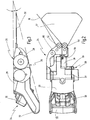
- the device 10 comprises a winding device 24 for winding a cutting means 18, which serves for severing an adhesive bead 34 of a vehicle window 12.
- the vehicle window 12 may be, for example, a windshield of a motor vehicle, which is glued to a body flange 14 by means of the adhesive bead 34, which consists of a very tough plastic material, such as polyurethane adhesive.
- the adhesive bead 34 is extremely stable and contributes to the inherent stability of the vehicle.
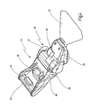
- the winding device 24 has a housing 20, at one end of a handle 22 is provided. Starting from the handle 22, the housing 20 tapers according to Fig. 3 approximately wedge-shaped toward the opposite end to which a support 32 is removably attached.
- the cutting means 18 can be wound by means of an electric drive 26 on a spool 28 or unwound therefrom. To guide the cutting means 18 to the coil 28 are on the support 32, two guide rollers 50, 52 provided by the largely tangential winding of the cutting means 18 is ensured on the spool.
- the cutting means 18 is first guided completely around the adhesive bead 34 from the outside. Then we fixed a first end either from the outside to a stationary vehicle part, for example to the windshield wiper shaft or with the help of a suction cup on the vehicle window itself from the outside or from the inside, to which a previous execution by the adhesive bead 34 is required. Then, the second end of the cutting means 18 is passed through the adhesive bead 34 and attached to the winding device 24. The winding device 24 is now supported with its support 32 on the frame or body flange 14 and the drive of the winding device 26 is actuated.
- the cutting means 18 is gradually pulled through the adhesive bead 34, so that it is severed.
- the angle 42 between the cutting means 18 and the body flange 14 should be kept as small as possible, whereby a good cutting action is achieved.
- the winding device 24 is thus gradually guided along with the support 32 along the frame 14 according to the progress of the cutting process, so that the angle between the cutting means and body flange 14 is not too large, as in Fig. 1 indicated by the dashed line position of the cutting means 18 'and the angle 42'. It is also conceivable to guide the support 32 along the adhesive bead 34.
- the support 32, on which the guide rollers 50, 52 are provided, by means of a clamping device 80 removably attached to the housing 20 of the winding device 24 is fixed (see. Fig. 2 ).
- the drive 26 has a DC motor 27, which is coupled via a gear 29 with the coil 28 to the drive.
- the motor 27 is powered by an accumulator 30 with power, which is removably attached to the housing 20. It will be understood, however, that instead of this a mains powered version may be used or that any other suitable type of drive, e.g. a compressed air drive can be used.
- the cutting means 18 When driving the spool 28, the cutting means 18 is wound in the working direction via the guide rollers 50, 52 through an opening 70 on the spool 28.
- the housing 20 of the winding device 24, starting from the handle 22 tapers approximately wedge-shaped with an angle ⁇ of about 13 ° to the opposite end, to which the support 32 is attached.
- the angle ⁇ is preferably in a range of about 10 to 30 °.
- the winding device 24 is formed at its the body flange 14 during use facing the end relatively narrow, so that a support on the frame or body flange 14 even with obstacles, as they occur on dashboards, is relatively easy. It is understood that for this purpose a respective suitable support 32 can be used, which is adapted to the geometric conditions in the respective vehicle model.
- the removal process by winding the cutting means 18 on the spool 28 in the working direction must usually be interrupted several times, since the winding device 24 must be moved past obstacles on the dashboard and must be re-attached to the support 32 on the frame or body flange 14. Partial this is an intermediate withdrawal of the cutting means 18 from the coil 28 is required.
- the strain relief device 36 may comprise a mechanical one-way clutch, which is directly coupled to the transmission 29. Thereby, a withdrawal of the cutting means 18 is made possible from the coil 28 when the drive 26 is not activated.
- the winding device 24 is provided with an intelligent controller 46, which detects when the drive 26 is switched off that a force is exerted on the cutting means 18 in order to pull it out of the coil 28.
- the winding device 24 supports the user in this case by the coil 28 is driven counter to the working direction, so that the cutting means 18 is unwound from the coil 28 again.
- the arrangement is preferably now made so that the cutting means 18 is unwound the faster, the greater the tensile force exerted on the cutting means 18.
- the unwinding process is terminated as soon as the user no longer pulls on the winding device 24, or when a switch 44 for activating the drive 26 is actuated.
- the switch 44 is designed as a throttle switch and is according to Fig. 4 received directly on the handle 22.
- the accelerator switch 44 is actuated by a pusher. Via the accelerator switch 44, the user can control the desired reel speed and thus the cutting speed.
- Integrated in the drive train is also a mechanical clutch, the in Fig. 4 indicated by 49.
- the coupling 49 protects the cutting means 18 against overload and breakage.
- This overload protection 49 triggers as soon as the maximum permissible tensile force on the cutting means 18 is reached. If the overload protection 49 triggers, this is signaled to the user, for which purpose an optical and / or acoustic signal means 48 is provided. Even if the strain relief device 36 is activated to pull the cutting means against the working direction of the coil 28 to be able to, this is indicated by a corresponding signal, to which also the signal means 48 can be used. For example, different beeps may be used to activate the strain relief device 36 and to activate the overload protection 49. Alternatively, a mechanical display, for example in the form of a ratchet or a vibration can be used.
Landscapes
- Life Sciences & Earth Sciences (AREA)
- Forests & Forestry (AREA)
- Engineering & Computer Science (AREA)
- Mechanical Engineering (AREA)
- Automobile Manufacture Line, Endless Track Vehicle, Trailer (AREA)
- Replacement Of Web Rolls (AREA)
- Processing And Handling Of Plastics And Other Materials For Molding In General (AREA)
Claims (12)
- Dispositif destiné au sectionnement du bourrelet adhésif (34) d'une vitre de véhicule (12), en particulier d'un pare-brise, comprenant un dispositif d'enroulement (24), comprenant une bobine (28) pour enrouler un moyen de coupe (18) dans la direction de travail pour le sectionnement du bourrelet adhésif (34), le dispositif d'enroulement (24) comportant un entraînement motorisé (26) qui est accouplé à une commande (46) pourvue d'un commutateur (44) pour mettre en marche l'entraînement (26), caractérisé en ce que le dispositif d'enroulement (24) comprend un dispositif de détente de traction (36) pour le moyen de coupe (18), lequel dispositif de détente de traction permet une sortie du moyen de coupe (18) hors du dispositif d'enroulement (24) en sens inverse à la direction de travail, et en ce que la commande (46) est réalisé de telle sorte que l'entraînement (26) soit entraîné en rotation en sens inverse à la direction de travail pendant un laps de temps déterminé après une déconnexion.
- Dispositif selon la revendication 1, caractérisé en ce que l'entraînement (26) peut être commuté entre la rotation dans le sens des aiguilles d'une montre et la rotation dans le sens contraire aux aiguilles d'une montre pour la détente de traction du moyen de coupe (18).
- Dispositif selon la revendication 1 ou 2, caractérisé en ce que le dispositif de détente de traction (36) comprend un accouplement à roue libre mécanique.
- Dispositif selon l'une quelconque des revendications 1 à 3, caractérisé en ce que la commande (46) est réalisée de telle sorte que l'entraînement (26) bobine le moyen de coupe (18) de nouveau jusqu'à l'état de départ lorsqu'aucune force de traction n'est exercée sur le moyen de coupe (18) après la déconnexion de l'entraînement (26).
- Dispositif selon la revendication 1 ou 2, caractérisé en ce que la commande (46) est réalisée de telle sorte que le moyen de coupe (18) soit bobiné après une déconnexion de l'entraînement (26) lorsqu'une force de traction est exercée sur le moyen de coupe (18).
- Dispositif selon la revendication 5, caractérisé en ce que la commande (46) est réalisée de telle sorte que le moyen de coupe (18) soit bobiné d'autant plus vite que la force de traction exercée sur le moyen de coupe (18) est élevée.
- Dispositif selon la revendication 5 ou 6, caractérisé en ce que la commande (46) est réalisée de telle sorte que l'opération de bobinage soit terminée lorsqu'aucune force de traction n'est plus exercée sur le moyen de coupe (18).
- Dispositif selon l'une quelconque des revendications précédentes, caractérisé en ce qu'un moyen de signalisation (48) est prévu, lequel signale une activation du dispositif de détente de traction (36).
- Dispositif selon l'une quelconque des revendications précédentes, caractérisé en ce que l'entraînement (26) comprend une protection contre les surcharges (44) dont le déclenchement est indiqué par un moyen de signalisation (48).
- Dispositif selon la revendication 9, caractérisé en ce que la protection contre les surcharges (49) comporte un accouplement pouvant être désaccouplé mécaniquement.
- Dispositif selon l'une quelconque des revendications précédentes, caractérisé en ce que le dispositif d'enroulement (24) comprend un entraînement (26) accouplé à la bobine (28), en ce que le dispositif d'enroulement (24) comprend une poignée (22) à une première extrémité, et en ce que le dispositif d'enroulement (24) comprend, à la deuxième extrémité opposée à la poignée (22), un support amovible (32) pour le guidage du dispositif d'enroulement (24) sur un cadre (14), auquel la vitre (12) est collée, ou sur le bourrelet adhésif (34).
- Dispositif selon la revendication 10 ou 11, caractérisé en ce que le dispositif d'enroulement comprend un boîtier (20) qui est réalisé approximativement de manière cunéiforme à partir du support (32) jusqu'à la poignée (22).
Applications Claiming Priority (1)
| Application Number | Priority Date | Filing Date | Title |
|---|---|---|---|
| DE200810060802 DE102008060802A1 (de) | 2008-12-01 | 2008-12-01 | Vorrichtung zum Durchtrennen des Klebewulstes von eingeklebten Scheiben |
Publications (3)
| Publication Number | Publication Date |
|---|---|
| EP2191945A2 EP2191945A2 (fr) | 2010-06-02 |
| EP2191945A3 EP2191945A3 (fr) | 2010-07-07 |
| EP2191945B1 true EP2191945B1 (fr) | 2015-06-03 |
Family
ID=41683448
Family Applications (1)
| Application Number | Title | Priority Date | Filing Date |
|---|---|---|---|
| EP09177355.6A Not-in-force EP2191945B1 (fr) | 2008-12-01 | 2009-11-27 | Dispositif destiné au sectionnement du bourrelet adhésif de vitres collées |
Country Status (4)
| Country | Link |
|---|---|
| US (1) | US8307873B2 (fr) |
| EP (1) | EP2191945B1 (fr) |
| CN (1) | CN101745929B (fr) |
| DE (1) | DE102008060802A1 (fr) |
Families Citing this family (12)
| Publication number | Priority date | Publication date | Assignee | Title |
|---|---|---|---|---|
| GB2517347B (en) * | 2010-02-19 | 2015-07-22 | Belron Hungary Kft Zug Branch | Wire handling for vehicle glazing panel cut out |
| GB2542724B (en) | 2010-11-22 | 2017-06-07 | Belron Hungary Kft - Zug Branch | Apparatus and method for cutting out a vehicle glazing panel |
| DE102011013790B4 (de) | 2011-03-03 | 2018-03-29 | C. & E. Fein Gmbh | Vorrichtung und Verfahren zum Durchtrennen des Klebewulstes von eingeklebten Scheiben |
| DE102011013890A1 (de) * | 2011-03-07 | 2012-09-13 | C. & E. Fein Gmbh | Vorrichtung und Verfahren zum Durchtrennen des Klebewulstes von eingeklebten Scheiben |
| US20140137416A1 (en) * | 2012-11-22 | 2014-05-22 | Horvath Iosif Robert | Cutting Blade Cutting Device |
| CN104044332A (zh) * | 2013-03-15 | 2014-09-17 | 纬创资通股份有限公司 | 拆解平板组的方法及拆解工具 |
| GB2526308B (en) * | 2014-05-20 | 2021-06-09 | Belron Int Ltd | Glazing panel removal |
| GB201418184D0 (en) * | 2014-10-14 | 2014-11-26 | Belron Hungary Kft Zug Branch | Apparatus and method for cutting out a vehicle glazing panel |
| US10227965B2 (en) * | 2015-03-23 | 2019-03-12 | Kent R. Mayhugh | Windshield removal assist device |
| GB201601500D0 (en) | 2016-01-27 | 2016-03-09 | Belron Hungary Kft Zug Branch | Winder unit for vehicle glazing panel cut out |
| WO2018218180A1 (fr) * | 2017-05-25 | 2018-11-29 | Rolladeck Industries, Inc. | Treuil d'enlèvement de pare-brise |
| CN119427447B (zh) * | 2025-01-08 | 2025-05-09 | 沈阳知为智能科技有限公司 | 一种飞机蒙皮切割装置 |
Family Cites Families (17)
| Publication number | Priority date | Publication date | Assignee | Title |
|---|---|---|---|---|
| US4215475A (en) * | 1978-06-12 | 1980-08-05 | Gould Kenneth D | Oscillating cut-out tool |
| US4227517A (en) * | 1979-01-29 | 1980-10-14 | Aguiar Robert H | Cast cutting system |
| US4601224A (en) * | 1984-10-05 | 1986-07-22 | Clark Iii William T | Hot wire cutting system |
| SE8502633D0 (sv) * | 1985-05-31 | 1985-05-29 | Folksam Auto Ab | Sett och anordning for demontering |
| DE4019933A1 (de) * | 1990-06-22 | 1992-01-09 | Bayerische Motoren Werke Ag | Schneidvorrichtung zum entfernen von klebstoffraupen bei geklebten fahrzeugscheiben |
| US5622093A (en) * | 1995-01-19 | 1997-04-22 | Equalizer Industries, Inc. | Automobile windshield removal apparatus and method |
| AUPN743896A0 (en) * | 1996-01-05 | 1996-02-01 | Lock, Trevor Stanley | Improvements in windscreen removal devices |
| DE29711291U1 (de) * | 1997-06-28 | 1997-09-04 | Eduard Wille Gmbh & Co, 42349 Wuppertal | Scheibentrenngerät |
| US6616800B2 (en) * | 2001-03-05 | 2003-09-09 | Rolf O. Eriksson | Method and device for removing windshields |
| WO2004014678A2 (fr) | 2002-08-09 | 2004-02-19 | Mobilglas 2000 Aps | Dispositif et procede pour guider un outil suivant un trajet sur une surface |
| NL1022127C2 (nl) * | 2002-12-10 | 2004-06-11 | Tetra Pak Tebel Bv | Kaasvat voor het bereiden van zachte verse kaas. |
| EP1628846B1 (fr) * | 2003-05-21 | 2010-04-21 | Ramhuset Dala-Speglar AB | Procede et dispositif permettant de retirer des glaces de vehicule |
| US20080012349A1 (en) * | 2005-09-14 | 2008-01-17 | William Finck | Vehicle Glazing Panel Cut Out |
| DE102006013417A1 (de) | 2006-03-14 | 2007-09-20 | C. & E. Fein Gmbh | Vorrichtung und Verfahren zum Durchtrennen des Klebewulstes einer Fahrzeugscheibe |
| WO2008001816A1 (fr) * | 2006-06-30 | 2008-01-03 | Nagasaki University | Procédé et dispositif de coupe |
| US20090283214A1 (en) * | 2008-05-16 | 2009-11-19 | Jack Richard Nelson | Device and method for separating adhesive |
| EP2191943B1 (fr) * | 2008-12-01 | 2013-01-16 | C. & E. Fein GmbH | Dispositif et procédé destinés au sectionnement du bourrelet adhésif de vitres collées |
-
2008
- 2008-12-01 DE DE200810060802 patent/DE102008060802A1/de not_active Withdrawn
-
2009
- 2009-11-27 EP EP09177355.6A patent/EP2191945B1/fr not_active Not-in-force
- 2009-12-01 US US12/628,660 patent/US8307873B2/en not_active Expired - Fee Related
- 2009-12-01 CN CN200910252804.XA patent/CN101745929B/zh not_active Expired - Fee Related
Also Published As
| Publication number | Publication date |
|---|---|
| EP2191945A3 (fr) | 2010-07-07 |
| DE102008060802A1 (de) | 2010-06-02 |
| CN101745929A (zh) | 2010-06-23 |
| EP2191945A2 (fr) | 2010-06-02 |
| US20100132201A1 (en) | 2010-06-03 |
| CN101745929B (zh) | 2014-05-14 |
| US8307873B2 (en) | 2012-11-13 |
Similar Documents
| Publication | Publication Date | Title |
|---|---|---|
| EP2191945B1 (fr) | Dispositif destiné au sectionnement du bourrelet adhésif de vitres collées | |
| EP1834741B1 (fr) | Dispositif et procédé destinés au sectionnement du bourrelet adhésif d'une vitre de véhicule | |
| EP2191943B1 (fr) | Dispositif et procédé destinés au sectionnement du bourrelet adhésif de vitres collées | |
| EP0093283B1 (fr) | Procédé et dispositif pour le détachement de vitres de véhicule | |
| DE102011013890A1 (de) | Vorrichtung und Verfahren zum Durchtrennen des Klebewulstes von eingeklebten Scheiben | |
| EP1123825B9 (fr) | Store à enrouleur pour fenêtre arrière | |
| EP2039547A2 (fr) | Store de fenêtre latérale doté d'une aide à l'introduction | |
| DE102008000802B4 (de) | Vollautomatisches Staufach | |
| EP2078490B1 (fr) | Appareil électrique doté d'un système d'enroulement de câble amélioré et procédé de fonctionnement d'un tel appareil électrique | |
| EP1609647A2 (fr) | Store à enrouler avec couvercle sur la fente extracte | |
| EP1886853A1 (fr) | Store de fenêtre doté d'un actionnement par le lève-glace | |
| DE102018211344A1 (de) | Kabelwickelsystem sowie Verfahren zum Betreiben eines Kabelwickelsystems | |
| WO2010040521A1 (fr) | Dispositif pour ouvrir une ligne | |
| DE102011013790B4 (de) | Vorrichtung und Verfahren zum Durchtrennen des Klebewulstes von eingeklebten Scheiben | |
| EP2540463B1 (fr) | Dispositif et méthode destiné au sectionnement du bourrelet adhésif de vitres collées | |
| EP2565144A1 (fr) | Treuil de câble | |
| EP2444585A2 (fr) | Procédé de surveillance de mouvements sur un portail roulant et dispositif d'exécution du procédé | |
| DE102008060812A1 (de) | Vorrichtung und Verfahren zum Druchtrennen des Klebewulstes von eingeklebten Scheiben | |
| DE102016118948B4 (de) | Fahrzeugaufprallsystem mit einem angetriebenen Barrierewagen | |
| DE102009010463A1 (de) | Vorrichtung zum Durchtrennen des Klebewulstes von eingeklebten Scheiben | |
| DE102005021399A1 (de) | Rollo für Fahrzeugfenster | |
| EP0618160A2 (fr) | Bobine de papier, station de déballage d'une bobine de papier et méthode pour déballer une bobine de papier | |
| DE2455913B2 (de) | Kopswechselvorrichtung | |
| DE102008060811A1 (de) | Vorrichtung zum Durchtrennen des Klebewulstes von eingeklebten Scheiben | |
| DE102024128694A1 (de) | Handgehaltener Klebebandspender |
Legal Events
| Date | Code | Title | Description |
|---|---|---|---|
| PUAI | Public reference made under article 153(3) epc to a published international application that has entered the european phase |
Free format text: ORIGINAL CODE: 0009012 |
|
| AK | Designated contracting states |
Kind code of ref document: A2 Designated state(s): AT BE BG CH CY CZ DE DK EE ES FI FR GB GR HR HU IE IS IT LI LT LU LV MC MK MT NL NO PL PT RO SE SI SK SM TR |
|
| AX | Request for extension of the european patent |
Extension state: AL BA RS |
|
| PUAL | Search report despatched |
Free format text: ORIGINAL CODE: 0009013 |
|
| AK | Designated contracting states |
Kind code of ref document: A3 Designated state(s): AT BE BG CH CY CZ DE DK EE ES FI FR GB GR HR HU IE IS IT LI LT LU LV MC MK MT NL NO PL PT RO SE SI SK SM TR |
|
| AX | Request for extension of the european patent |
Extension state: AL BA RS |
|
| 17P | Request for examination filed |
Effective date: 20101230 |
|
| 17Q | First examination report despatched |
Effective date: 20120710 |
|
| RIC1 | Information provided on ipc code assigned before grant |
Ipc: B26D 1/547 20060101AFI20141106BHEP |
|
| GRAP | Despatch of communication of intention to grant a patent |
Free format text: ORIGINAL CODE: EPIDOSNIGR1 |
|
| INTG | Intention to grant announced |
Effective date: 20141211 |
|
| RIN1 | Information on inventor provided before grant (corrected) |
Inventor name: CLABUNDE, JOACHIM Inventor name: BLICKLE, JUERGEN Inventor name: KLABUNDE, OLAF Inventor name: MAYER, BERND |
|
| GRAS | Grant fee paid |
Free format text: ORIGINAL CODE: EPIDOSNIGR3 |
|
| GRAA | (expected) grant |
Free format text: ORIGINAL CODE: 0009210 |
|
| AK | Designated contracting states |
Kind code of ref document: B1 Designated state(s): AT BE BG CH CY CZ DE DK EE ES FI FR GB GR HR HU IE IS IT LI LT LU LV MC MK MT NL NO PL PT RO SE SI SK SM TR |
|
| REG | Reference to a national code |
Ref country code: GB Ref legal event code: FG4D Free format text: NOT ENGLISH |
|
| REG | Reference to a national code |
Ref country code: CH Ref legal event code: EP |
|
| REG | Reference to a national code |
Ref country code: AT Ref legal event code: REF Ref document number: 729675 Country of ref document: AT Kind code of ref document: T Effective date: 20150715 Ref country code: IE Ref legal event code: FG4D Free format text: LANGUAGE OF EP DOCUMENT: GERMAN |
|
| REG | Reference to a national code |
Ref country code: DE Ref legal event code: R096 Ref document number: 502009011096 Country of ref document: DE |
|
| PG25 | Lapsed in a contracting state [announced via postgrant information from national office to epo] |
Ref country code: ES Free format text: LAPSE BECAUSE OF FAILURE TO SUBMIT A TRANSLATION OF THE DESCRIPTION OR TO PAY THE FEE WITHIN THE PRESCRIBED TIME-LIMIT Effective date: 20150603 Ref country code: FI Free format text: LAPSE BECAUSE OF FAILURE TO SUBMIT A TRANSLATION OF THE DESCRIPTION OR TO PAY THE FEE WITHIN THE PRESCRIBED TIME-LIMIT Effective date: 20150603 Ref country code: HR Free format text: LAPSE BECAUSE OF FAILURE TO SUBMIT A TRANSLATION OF THE DESCRIPTION OR TO PAY THE FEE WITHIN THE PRESCRIBED TIME-LIMIT Effective date: 20150603 Ref country code: NO Free format text: LAPSE BECAUSE OF FAILURE TO SUBMIT A TRANSLATION OF THE DESCRIPTION OR TO PAY THE FEE WITHIN THE PRESCRIBED TIME-LIMIT Effective date: 20150903 Ref country code: LT Free format text: LAPSE BECAUSE OF FAILURE TO SUBMIT A TRANSLATION OF THE DESCRIPTION OR TO PAY THE FEE WITHIN THE PRESCRIBED TIME-LIMIT Effective date: 20150603 |
|
| REG | Reference to a national code |
Ref country code: NL Ref legal event code: MP Effective date: 20150603 |
|
| REG | Reference to a national code |
Ref country code: LT Ref legal event code: MG4D |
|
| PG25 | Lapsed in a contracting state [announced via postgrant information from national office to epo] |
Ref country code: LV Free format text: LAPSE BECAUSE OF FAILURE TO SUBMIT A TRANSLATION OF THE DESCRIPTION OR TO PAY THE FEE WITHIN THE PRESCRIBED TIME-LIMIT Effective date: 20150603 Ref country code: GR Free format text: LAPSE BECAUSE OF FAILURE TO SUBMIT A TRANSLATION OF THE DESCRIPTION OR TO PAY THE FEE WITHIN THE PRESCRIBED TIME-LIMIT Effective date: 20150904 Ref country code: BG Free format text: LAPSE BECAUSE OF FAILURE TO SUBMIT A TRANSLATION OF THE DESCRIPTION OR TO PAY THE FEE WITHIN THE PRESCRIBED TIME-LIMIT Effective date: 20150903 |
|
| PG25 | Lapsed in a contracting state [announced via postgrant information from national office to epo] |
Ref country code: EE Free format text: LAPSE BECAUSE OF FAILURE TO SUBMIT A TRANSLATION OF THE DESCRIPTION OR TO PAY THE FEE WITHIN THE PRESCRIBED TIME-LIMIT Effective date: 20150603 |
|
| PG25 | Lapsed in a contracting state [announced via postgrant information from national office to epo] |
Ref country code: RO Free format text: LAPSE BECAUSE OF NON-PAYMENT OF DUE FEES Effective date: 20150603 Ref country code: SK Free format text: LAPSE BECAUSE OF FAILURE TO SUBMIT A TRANSLATION OF THE DESCRIPTION OR TO PAY THE FEE WITHIN THE PRESCRIBED TIME-LIMIT Effective date: 20150603 Ref country code: PL Free format text: LAPSE BECAUSE OF FAILURE TO SUBMIT A TRANSLATION OF THE DESCRIPTION OR TO PAY THE FEE WITHIN THE PRESCRIBED TIME-LIMIT Effective date: 20150603 Ref country code: IS Free format text: LAPSE BECAUSE OF FAILURE TO SUBMIT A TRANSLATION OF THE DESCRIPTION OR TO PAY THE FEE WITHIN THE PRESCRIBED TIME-LIMIT Effective date: 20151003 Ref country code: CZ Free format text: LAPSE BECAUSE OF FAILURE TO SUBMIT A TRANSLATION OF THE DESCRIPTION OR TO PAY THE FEE WITHIN THE PRESCRIBED TIME-LIMIT Effective date: 20150603 Ref country code: PT Free format text: LAPSE BECAUSE OF FAILURE TO SUBMIT A TRANSLATION OF THE DESCRIPTION OR TO PAY THE FEE WITHIN THE PRESCRIBED TIME-LIMIT Effective date: 20151006 |
|
| REG | Reference to a national code |
Ref country code: DE Ref legal event code: R097 Ref document number: 502009011096 Country of ref document: DE |
|
| PLBE | No opposition filed within time limit |
Free format text: ORIGINAL CODE: 0009261 |
|
| STAA | Information on the status of an ep patent application or granted ep patent |
Free format text: STATUS: NO OPPOSITION FILED WITHIN TIME LIMIT |
|
| PG25 | Lapsed in a contracting state [announced via postgrant information from national office to epo] |
Ref country code: DK Free format text: LAPSE BECAUSE OF FAILURE TO SUBMIT A TRANSLATION OF THE DESCRIPTION OR TO PAY THE FEE WITHIN THE PRESCRIBED TIME-LIMIT Effective date: 20150603 Ref country code: IT Free format text: LAPSE BECAUSE OF FAILURE TO SUBMIT A TRANSLATION OF THE DESCRIPTION OR TO PAY THE FEE WITHIN THE PRESCRIBED TIME-LIMIT Effective date: 20150603 |
|
| 26N | No opposition filed |
Effective date: 20160304 |
|
| PG25 | Lapsed in a contracting state [announced via postgrant information from national office to epo] |
Ref country code: SI Free format text: LAPSE BECAUSE OF FAILURE TO SUBMIT A TRANSLATION OF THE DESCRIPTION OR TO PAY THE FEE WITHIN THE PRESCRIBED TIME-LIMIT Effective date: 20150603 |
|
| PG25 | Lapsed in a contracting state [announced via postgrant information from national office to epo] |
Ref country code: MC Free format text: LAPSE BECAUSE OF FAILURE TO SUBMIT A TRANSLATION OF THE DESCRIPTION OR TO PAY THE FEE WITHIN THE PRESCRIBED TIME-LIMIT Effective date: 20150603 Ref country code: LU Free format text: LAPSE BECAUSE OF FAILURE TO SUBMIT A TRANSLATION OF THE DESCRIPTION OR TO PAY THE FEE WITHIN THE PRESCRIBED TIME-LIMIT Effective date: 20151127 |
|
| REG | Reference to a national code |
Ref country code: CH Ref legal event code: PL |
|
| GBPC | Gb: european patent ceased through non-payment of renewal fee |
Effective date: 20151127 |
|
| PG25 | Lapsed in a contracting state [announced via postgrant information from national office to epo] |
Ref country code: CH Free format text: LAPSE BECAUSE OF NON-PAYMENT OF DUE FEES Effective date: 20151130 Ref country code: LI Free format text: LAPSE BECAUSE OF NON-PAYMENT OF DUE FEES Effective date: 20151130 |
|
| REG | Reference to a national code |
Ref country code: IE Ref legal event code: MM4A |
|
| REG | Reference to a national code |
Ref country code: FR Ref legal event code: ST Effective date: 20160729 |
|
| PG25 | Lapsed in a contracting state [announced via postgrant information from national office to epo] |
Ref country code: GB Free format text: LAPSE BECAUSE OF NON-PAYMENT OF DUE FEES Effective date: 20151127 Ref country code: IE Free format text: LAPSE BECAUSE OF NON-PAYMENT OF DUE FEES Effective date: 20151127 |
|
| PG25 | Lapsed in a contracting state [announced via postgrant information from national office to epo] |
Ref country code: FR Free format text: LAPSE BECAUSE OF NON-PAYMENT OF DUE FEES Effective date: 20151130 |
|
| REG | Reference to a national code |
Ref country code: AT Ref legal event code: MM01 Ref document number: 729675 Country of ref document: AT Kind code of ref document: T Effective date: 20151127 |
|
| PG25 | Lapsed in a contracting state [announced via postgrant information from national office to epo] |
Ref country code: AT Free format text: LAPSE BECAUSE OF NON-PAYMENT OF DUE FEES Effective date: 20151127 |
|
| PG25 | Lapsed in a contracting state [announced via postgrant information from national office to epo] |
Ref country code: SM Free format text: LAPSE BECAUSE OF FAILURE TO SUBMIT A TRANSLATION OF THE DESCRIPTION OR TO PAY THE FEE WITHIN THE PRESCRIBED TIME-LIMIT Effective date: 20150603 Ref country code: HU Free format text: LAPSE BECAUSE OF FAILURE TO SUBMIT A TRANSLATION OF THE DESCRIPTION OR TO PAY THE FEE WITHIN THE PRESCRIBED TIME-LIMIT; INVALID AB INITIO Effective date: 20091127 |
|
| PG25 | Lapsed in a contracting state [announced via postgrant information from national office to epo] |
Ref country code: NL Free format text: LAPSE BECAUSE OF FAILURE TO SUBMIT A TRANSLATION OF THE DESCRIPTION OR TO PAY THE FEE WITHIN THE PRESCRIBED TIME-LIMIT Effective date: 20150603 Ref country code: SE Free format text: LAPSE BECAUSE OF FAILURE TO SUBMIT A TRANSLATION OF THE DESCRIPTION OR TO PAY THE FEE WITHIN THE PRESCRIBED TIME-LIMIT Effective date: 20150603 Ref country code: CY Free format text: LAPSE BECAUSE OF FAILURE TO SUBMIT A TRANSLATION OF THE DESCRIPTION OR TO PAY THE FEE WITHIN THE PRESCRIBED TIME-LIMIT Effective date: 20150603 |
|
| PG25 | Lapsed in a contracting state [announced via postgrant information from national office to epo] |
Ref country code: BE Free format text: LAPSE BECAUSE OF NON-PAYMENT OF DUE FEES Effective date: 20151130 |
|
| PG25 | Lapsed in a contracting state [announced via postgrant information from national office to epo] |
Ref country code: TR Free format text: LAPSE BECAUSE OF FAILURE TO SUBMIT A TRANSLATION OF THE DESCRIPTION OR TO PAY THE FEE WITHIN THE PRESCRIBED TIME-LIMIT Effective date: 20150603 Ref country code: MT Free format text: LAPSE BECAUSE OF FAILURE TO SUBMIT A TRANSLATION OF THE DESCRIPTION OR TO PAY THE FEE WITHIN THE PRESCRIBED TIME-LIMIT Effective date: 20150603 |
|
| PGFP | Annual fee paid to national office [announced via postgrant information from national office to epo] |
Ref country code: DE Payment date: 20171121 Year of fee payment: 9 |
|
| PG25 | Lapsed in a contracting state [announced via postgrant information from national office to epo] |
Ref country code: MK Free format text: LAPSE BECAUSE OF FAILURE TO SUBMIT A TRANSLATION OF THE DESCRIPTION OR TO PAY THE FEE WITHIN THE PRESCRIBED TIME-LIMIT Effective date: 20150603 |
|
| REG | Reference to a national code |
Ref country code: DE Ref legal event code: R119 Ref document number: 502009011096 Country of ref document: DE |
|
| PG25 | Lapsed in a contracting state [announced via postgrant information from national office to epo] |
Ref country code: DE Free format text: LAPSE BECAUSE OF NON-PAYMENT OF DUE FEES Effective date: 20190601 |