EP2191976A2 - Verfahren zum Markieren oder Beschriften eines Werkstücks - Google Patents
Verfahren zum Markieren oder Beschriften eines Werkstücks Download PDFInfo
- Publication number
- EP2191976A2 EP2191976A2 EP09176050A EP09176050A EP2191976A2 EP 2191976 A2 EP2191976 A2 EP 2191976A2 EP 09176050 A EP09176050 A EP 09176050A EP 09176050 A EP09176050 A EP 09176050A EP 2191976 A2 EP2191976 A2 EP 2191976A2
- Authority
- EP
- European Patent Office
- Prior art keywords
- workpiece
- polymer matrix
- radiation
- liquid film
- liquid
- Prior art date
- Legal status (The legal status is an assumption and is not a legal conclusion. Google has not performed a legal analysis and makes no representation as to the accuracy of the status listed.)
- Granted
Links
Images
Classifications
-
- B—PERFORMING OPERATIONS; TRANSPORTING
- B23—MACHINE TOOLS; METAL-WORKING NOT OTHERWISE PROVIDED FOR
- B23K—SOLDERING OR UNSOLDERING; WELDING; CLADDING OR PLATING BY SOLDERING OR WELDING; CUTTING BY APPLYING HEAT LOCALLY, e.g. FLAME CUTTING; WORKING BY LASER BEAM
- B23K26/00—Working by laser beam, e.g. welding, cutting or boring
- B23K26/18—Working by laser beam, e.g. welding, cutting or boring using absorbing layers on the workpiece, e.g. for marking or protecting purposes
-
- B—PERFORMING OPERATIONS; TRANSPORTING
- B41—PRINTING; LINING MACHINES; TYPEWRITERS; STAMPS
- B41M—PRINTING, DUPLICATING, MARKING, OR COPYING PROCESSES; COLOUR PRINTING
- B41M5/00—Duplicating or marking methods; Sheet materials for use therein
- B41M5/26—Thermography ; Marking by high energetic means, e.g. laser otherwise than by burning, and characterised by the material used
- B41M5/262—Thermography ; Marking by high energetic means, e.g. laser otherwise than by burning, and characterised by the material used recording or marking of inorganic surfaces or materials, e.g. glass, metal, or ceramics
-
- C—CHEMISTRY; METALLURGY
- C03—GLASS; MINERAL OR SLAG WOOL
- C03C—CHEMICAL COMPOSITION OF GLASSES, GLAZES OR VITREOUS ENAMELS; SURFACE TREATMENT OF GLASS; SURFACE TREATMENT OF FIBRES OR FILAMENTS MADE FROM GLASS, MINERALS OR SLAGS; JOINING GLASS TO GLASS OR OTHER MATERIALS
- C03C17/00—Surface treatment of glass, not in the form of fibres or filaments, by coating
- C03C17/001—General methods for coating; Devices therefor
- C03C17/002—General methods for coating; Devices therefor for flat glass, e.g. float glass
-
- C—CHEMISTRY; METALLURGY
- C03—GLASS; MINERAL OR SLAG WOOL
- C03C—CHEMICAL COMPOSITION OF GLASSES, GLAZES OR VITREOUS ENAMELS; SURFACE TREATMENT OF GLASS; SURFACE TREATMENT OF FIBRES OR FILAMENTS MADE FROM GLASS, MINERALS OR SLAGS; JOINING GLASS TO GLASS OR OTHER MATERIALS
- C03C17/00—Surface treatment of glass, not in the form of fibres or filaments, by coating
- C03C17/28—Surface treatment of glass, not in the form of fibres or filaments, by coating with organic material
- C03C17/32—Surface treatment of glass, not in the form of fibres or filaments, by coating with organic material with synthetic or natural resins
-
- C—CHEMISTRY; METALLURGY
- C23—COATING METALLIC MATERIAL; COATING MATERIAL WITH METALLIC MATERIAL; CHEMICAL SURFACE TREATMENT; DIFFUSION TREATMENT OF METALLIC MATERIAL; COATING BY VACUUM EVAPORATION, BY SPUTTERING, BY ION IMPLANTATION OR BY CHEMICAL VAPOUR DEPOSITION, IN GENERAL; INHIBITING CORROSION OF METALLIC MATERIAL OR INCRUSTATION IN GENERAL
- C23C—COATING METALLIC MATERIAL; COATING MATERIAL WITH METALLIC MATERIAL; SURFACE TREATMENT OF METALLIC MATERIAL BY DIFFUSION INTO THE SURFACE, BY CHEMICAL CONVERSION OR SUBSTITUTION; COATING BY VACUUM EVAPORATION, BY SPUTTERING, BY ION IMPLANTATION OR BY CHEMICAL VAPOUR DEPOSITION, IN GENERAL
- C23C14/00—Coating by vacuum evaporation, by sputtering or by ion implantation of the coating forming material
- C23C14/04—Coating on selected surface areas, e.g. using masks
- C23C14/048—Coating on selected surface areas, e.g. using masks using irradiation by energy or particles
-
- C—CHEMISTRY; METALLURGY
- C23—COATING METALLIC MATERIAL; COATING MATERIAL WITH METALLIC MATERIAL; CHEMICAL SURFACE TREATMENT; DIFFUSION TREATMENT OF METALLIC MATERIAL; COATING BY VACUUM EVAPORATION, BY SPUTTERING, BY ION IMPLANTATION OR BY CHEMICAL VAPOUR DEPOSITION, IN GENERAL; INHIBITING CORROSION OF METALLIC MATERIAL OR INCRUSTATION IN GENERAL
- C23C—COATING METALLIC MATERIAL; COATING MATERIAL WITH METALLIC MATERIAL; SURFACE TREATMENT OF METALLIC MATERIAL BY DIFFUSION INTO THE SURFACE, BY CHEMICAL CONVERSION OR SUBSTITUTION; COATING BY VACUUM EVAPORATION, BY SPUTTERING, BY ION IMPLANTATION OR BY CHEMICAL VAPOUR DEPOSITION, IN GENERAL
- C23C14/00—Coating by vacuum evaporation, by sputtering or by ion implantation of the coating forming material
- C23C14/22—Coating by vacuum evaporation, by sputtering or by ion implantation of the coating forming material characterised by the process of coating
- C23C14/24—Vacuum evaporation
- C23C14/28—Vacuum evaporation by wave energy or particle radiation
Definitions
- the present invention relates to a method for marking or marking a workpiece with high-energy radiation, in particular with a laser beam, wherein the workpiece is transparent to the radiation wavelength, and wherein a polymer matrix is arranged in the vicinity of the workpiece such that the radiation passes through the workpiece, before it hits the polymer matrix.
- the absorbent polymer matrix is placed in direct contact with the transparent workpiece so that the laser beam passes through the workpiece and upon impact with the interface between the workpiece and polymer matrix vaporizes the material of the polymer matrix and settles on the surface of the workpiece as a marking or label separates.
- the known methods in this regard have several disadvantages.
- the distance between the workpiece and the polymer matrix must be as small as possible, so that the vaporized material is deposited on the workpiece as small as possible.
- a polymer matrix in the form of a transfer film can be adhered to the workpiece.
- a distance between polymer matrix and workpiece then brings several disadvantages.
- reactants provided in the polymer matrix react in a closed reaction space to the product. Through an opening to an air gap between the polymer matrix and the workpiece, the formation of such a reaction space can not be achieved.
- spatter occurs, which contains unwanted by-products, which likewise originate from the polymer matrix. As little as possible of this smut should mix as debris in or around the mark or label on the workpiece. The smoke development is greater with air entrapment between polymer matrix and workpiece and causes unclean results.
- laser methods are known which are based on increasing the near-surface absorption of laser radiation by a liquid.
- an absorbing medium is used deliberately, usually an organic liquid.
- the transparent workpiece is in contact with the liquid at the rear side to be processed, and the laser irradiation takes place through the front side.
- the heat transport from the heated liquid causes a rapid rise in temperature up to above the melting and evaporation point of the glass matrix.
- This process referred to as "laser-induced backside wet etching” (LIBWE), leads to material removal on the glass surface and is used for microstructuring or microgravelling glass.
- LIBWE laser-induced backside wet etching
- a wetting absorber liquid is selected, unwanted air entrapment between the liquid and the workpiece can be avoided.
- a disadvantage of a liquid as an absorber is that no localized material removal and no subsequent localized deposition on the workpiece are achieved can, but only one produced by heat removal of material on the workpiece, so for example only an engraving.
- the object of the present invention is therefore to provide an improved method for marking or marking a workpiece with high-energy radiation, in particular with a laser beam, in which the disadvantages of the known methods are overcome and also with rough, moist, uneven or soiled surfaces of the workpiece high quality and resolution can be marked or labeled.
- a method for marking or marking a workpiece with high-energy radiation, in particular with a laser beam.
- the workpiece is transparent to the radiation wavelength and a polymer matrix is placed in the vicinity of the workpiece so that the radiation passes through the workpiece before it hits the polymer matrix.
- the method is characterized in that a liquid film which is in contact with the polymer matrix and the workpiece is arranged between the polymer matrix and the workpiece.
- any matrix based on polymeric constituents is referred to herein.
- the matrix may also contain any non-polymeric constituents, with only the main constituent of polymeric nature should be.
- the term "polymer matrix” also refers to a mixture of base polymers.
- the polymer matrix is a thermoset polymer matrix. It has have been shown that, in particular, thermosets are particularly suitable for marking or labeling a workpiece.
- the inventive arrangement of the liquid film overcomes several disadvantages of the prior art.
- a distance between the workpiece and the polymer matrix is filled by the liquid.
- the preferably wetting liquid film has a refractive index similar to that of the workpiece, the optically rough surface is smoothed so that the laser beam can pass through the workpiece with no disturbing total reflections and scattering caused by the optically rough surface and with a significantly reduced reflectance.
- the liquid film limits the expansion of the area on which the material of the polymer matrix deposits. Because of the high energy input, the liquid film evaporates locally and forms a tunnel-like bubble through which the removed material laterally moves towards the workpiece.
- the resolution is thus not significantly affected despite a distance between the workpiece and polymer matrix.
- the liquid film prevents the formation of smoke or the smoke is dissolved or suspended in the liquid film. This significantly improves the quality and purity of the marking and labeling.
- the method according to the invention also has an advantage over direct contact between the workpiece and the polymer matrix, namely the function of the liquid film as a heat insulation layer or heat dissipator, which minimizes unwanted heating of the workpiece.
- the liquid film is preferably as transparent as possible to the laser radiation and therefore hardly absorbs laser radiation energy itself, but only the heat of the heated polymer matrix. This is done by conduction and convection with movement by the local evaporation of the liquid transported away and not locally concentrated transferred to the workpiece.
- the liquid or viscoelastic medium has a similar refractive index as the material of the workpiece. It has been found that with a difference of the refractive indices of less than 0.5 sufficiently good results are achieved.
- a laser is preferably used, which is suitable for marking, labeling or engraving of workpieces.
- This is, for example, a fiber-coupled solid-state diode laser such as a FAYb fiber laser (Fiber Amplified Ytterbium) with a wavelength of 1064 nm and an average power of 12 to 15 W.
- a fiber-coupled solid-state diode laser such as a FAYb fiber laser (Fiber Amplified Ytterbium) with a wavelength of 1064 nm and an average power of 12 to 15 W.
- the liquid or viscoelastic medium in the wavelength range of 600 nm - 1500 nm shows no absorption or has an absorption degree of less than 10%.
- the material of the workpiece which is preferably a glass substrate. Contrary to the described LIBWE method, so here is a liquid is used, which has a low or no absorbance at the wavelength used.
- the material causes material removal on the polymer matrix and the liquid film absorbs removed components of the polymer matrix and / or products resulting therefrom.
- the polymer matrix may comprise, for example, a titanium dispenser and a carbon dispenser.
- the titanium dispenser is pure titanium or a titanium compound that has an affinity has to temporarily provide free titanium as a starting material under the action of energy.
- the provision of the free titanium may also be via the path of a titanium-containing intermediate.
- the carbon dispenser provides free carbon in particular under energy irradiation.
- the carbon donor may be a carbon compound and / or free, unbound carbon.
- the carbon donor can be provided by the polymer matrix itself, but it can also be an additional carbon component, for example in the form of carbon black, be present.
- the polymer matrix may also contain other components such as polymers, absorbers, etc.
- the radiation causes the starting materials titanium and carbon to be provided, for example by breaking up a titanium compound and a carbon compound, and titanium carbide is formed under the action of radiation as the desired product.
- titanium dioxide is reduced with carbon black or pure graphite to titanium carbide and carbon monoxide at a local temperature of 1700 ° C to 2200 ° C.
- the radiation causes the temperature necessary for the reaction in the reaction space.
- the polymer matrix is designed such that it reacts to the laser irradiation predominantly with pulverization, whereby the individual reactants, in particular titanium and carbon, are released and are available for the reaction to titanium carbide.
- a liquid is selected for the liquid film which shows no absorption in the wavelength range of 600-1500 nm or has an absorbance of less than 10% and radiation in the wavelength range of 600-1500 nm is used . It can be a sol, gel or a liquid film for the liquid Viscoelastic substance can be selected, wherein the liquid film may have a layer thickness of 250 nm - 10 mm.
- the liquid may also itself contain ingredients provided as starting materials or catalysts for desired reactions. If appropriate, ions which are available as starting materials or catalysts for a desired reaction to form a product can dissolve in the liquid film, the product then being able to deposit on the workpiece under the action of high-energy radiation.
- the liquid film preferably changes its state of aggregation locally under the action of the radiation and in particular becomes gaseous. This creates a spatially limited tunnel-like space for depositing the removed material or the products thereof on the smallest possible area of the workpiece.
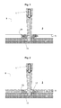
- Fig. 1 shows an adverse process in which there is an air layer between the workpiece and polymer matrix.
- Fig. 2 shows an advantageous method in which a liquid film between the workpiece and polymer matrix is located.
- a laser beam 1 is directed onto a workpiece 3 in the form of a glass substrate to be marked or labeled on a surface 5.
- a polymer matrix 7 is arranged at a distance. Between polymer matrix 7 and workpiece 3 is therefore an air gap.
- the air gap can be deliberately arranged or unconsciously by a roughness, unevenness, Moisture or dirt on the surface 5 of the workpiece or the polymer matrix 7 conditional.
- the workpiece 3 is transparent to the wavelength of the laser beam 1, whereas the polymer matrix 7 mainly absorbs the laser beam 1.
- the laser beam 1 enters the workpiece 3 via a surface 9 of the workpiece 3 which is opposite to the surface 5 to be marked, passes through it and strikes the polymer matrix 7, which absorbs the laser beam 1 and heats up until the thermal energy is so high in that the polymer matrix 7 is pulverized.
- a reaction space 11 which is open towards the air gap arises within the polymer matrix 7, in which educts are present in the pulverized material, which are ready for a desired reaction.
- the educts in this example are titanium dioxide and pure carbon in the form of carbon black, wherein the titanium dioxide is to be reduced at a local temperature generated by the radiation of 1700 ° C to 2200 ° C to titanium carbide as a product for deposition as marking or lettering.
- the reaction space 11 since the reaction space 11 is open to the air gap, the pulverization causes a strong development of smoke 13 and other undesirable by-products.
- the abraded material escapes prematurely with the smoke 13 and other by-products from the reaction chamber 11 into the air gap, without causing a reaction to titanium carbide and deposition on the surface 5 of the workpiece 3.
- the surface 5 of the workpiece 3 is only soiled with smoke and other undesirable by-products.
- FIG. 2 shows an advantageous embodiment of the method, in which between the surface 5 of the workpiece 3 and the polymer matrix 7, a liquid film 15 is arranged.
- the surface 5 of the workpiece 3 or the polymer matrix 7 with a liquid amount of 0.1 ml via a pipette drizzled and distributed in an area of 5 cm x 5 cm. Due to the surface tension, it may be necessary to create a uniform liquid film by movement of the glass plate or by an air jet or to make the liquid wetting by additives.
- the fluid is demineralized water, which is commonly used in the chemical and pharmaceutical industries.
- the polymer matrix is applied as a film material to the liquid film 15 so that a liquid film 15 is formed with a film thickness of 20 .mu.m to 100 .mu.m. It is also possible to apply the liquid to the polymer matrix 7 and to produce the surface tension caused by the placement of the workpiece 3 in the size of 48 x 14 mm, a uniform distribution of the liquid.
- the film thickness can be determined by a spacer between polymer film 7 and glass 3. If possible, care must be taken that the film layer is distributed homogeneously and without air buildup at the interfaces.
- a solid state laser (not shown) emitting a wavelength of 1064 nm is used.
- a fiber-coupled diode laser is used, as this is offered by the company Panasonic Electric Works Europe AG in Germany under the trade name "SunX LP-V10".
- the laser radiation used is therefore the wavelength of 1064 nm, for which glass and water are permeable.
- the laser beam 1 passes through this medium and passes from the glass 3 to the water 15 at the interface. Also, water has no absorption capacity at this wavelength and allows the laser beam to strike the polymer matrix 7 with virtually no loss.
- the liquid film 15 evaporates and forms a tunnel-like bubble, which propagates to the surface 5 of the workpiece 3.
- the explosive shock wave titanium carbide is thrown onto the surface 5 of the workpiece 3, whereupon the titanium carbide deposits locally limited.
- the polymer matrix 7 is detached from the glass plate 3 and the smear-containing and particle-containing liquid film 15 is removed, wherein the deposited titanium carbide permanently remains as a marking or inscription 17 on the glass surface 5.
Landscapes
- Chemical & Material Sciences (AREA)
- Engineering & Computer Science (AREA)
- Chemical Kinetics & Catalysis (AREA)
- Materials Engineering (AREA)
- Organic Chemistry (AREA)
- Mechanical Engineering (AREA)
- Metallurgy (AREA)
- General Chemical & Material Sciences (AREA)
- Geochemistry & Mineralogy (AREA)
- Toxicology (AREA)
- Health & Medical Sciences (AREA)
- Life Sciences & Earth Sciences (AREA)
- Optics & Photonics (AREA)
- Physics & Mathematics (AREA)
- Ceramic Engineering (AREA)
- Plasma & Fusion (AREA)
- Laser Beam Processing (AREA)
- Thermal Transfer Or Thermal Recording In General (AREA)
- Treatments Of Macromolecular Shaped Articles (AREA)
- Exposure And Positioning Against Photoresist Photosensitive Materials (AREA)
Abstract
Description
- Die vorliegende Erfindung betrifft ein Verfahren zum Markieren oder Beschriften eines Werkstücks mit energiereicher Strahlung, insbesondere mit einem Laserstrahl, wobei das Werkstück für die Strahlungswellenlänge transparent ist, und wobei eine Polymermatrix derart in der Nähe des Werkstücks angeordnet wird, dass die Strahlung das Werkstück durchläuft, bevor sie auf die Polymermatrix trifft.
- Es ist bekannt, dass die Verwendung einer Laserstrahlung zur Materialbearbeitung eines Werkstücks grundlegend auf einer Absorption der Strahlung und einer Energieumwandlung mit nachfolgenden Prozessen wie Verdampfen, Ionisieren, partikulärem Abtragen und photochemischen Vorgängen basiert. Dabei können diese Prozesse im Werkstück selbst stattfinden, sodass Markierungen oder Beschriftungen beispielsweise in Form einer Gravur erzielt werden, oder ein anderes Material lokal auf dem Werkstück abgeschieden wird, beispielsweise im Rahmen von Laserstrahlverdampfen (engl. pulsed laser deposition, PLD). Varianten des Laserstrahlverdampfens finden insbesondere bei Werkstücken statt, deren Material transparent für die Wellenlänge der verwendeten Laserstrahlung ist.
- Beispielsweise wird die absorbierende Polymermatrix in direktem Kontakt mit dem transparenten Werkstück angeordnet, sodass der Laserstrahl das Werkstück durchläuft und beim Auftreffen auf die Grenzfläche zwischen Werkstück und Polymermatrix das Material der Polymermatrix verdampft und sich auf der Oberfläche des Werkstücks als Markierung oder Beschriftung abscheidet.
- Die diesbezüglich bekannten Verfahren haben mehrere Nachteile. Einerseits muss für eine möglichst hohe Auflösung der Markierung oder Beschriftung der Abstand zwischen Werkstück und Polymermatrix möglichst gering sein, damit sich das verdampfte Material auf möglichst kleiner Fläche auf dem Werkstück abscheidet. Hierzu kann beispielsweise eine Polymermatrix in Form einer Transferfolie auf das Werkstück aufgeklebt werden. Falls allerdings eine raue, feuchte, unebene oder verschmutzte Oberfläche des Werkstücks beschriftet werden soll, liegt zumindest lokal häufig kein direkter Kontakt zwischen Polymermatrix und Werkstück vor. Dies kann durch Einschluss von Luftblasen oder anderen flüssigen oder festen Verunreinigungen oder Unebenheiten bedingt sein. Ein Abstand zwischen Polymermatrix und Werkstück bringt dann mehrere Nachteile mit sich. Zum einen gibt es zwei zusätzliche Grenzflächen zwischen Werkstück (optisch dicht) und Luft (optisch dünn) einerseits und Luft (optisch dünn) und Polymermatrix (optisch dicht) andererseits. Dies führt zu unerwünschten Verlusten durch Streuung und Reflexion, wobei ein Teil der Leistung der Laserstrahlung nicht für den gewünschten Verdampfungsprozess zur Verfügung steht, sondern in unerwünschter oder sogar schädigender Weise Bereiche des Werkstücks und/oder der Polymermatrix aufheizt. Zum anderen verteilt sich das abgetragene Material der Polymermatrix auf einen umso größeren Flächenbereich, je größer der Abstand zwischen Polymermatrix und Werkstück ist. Damit wird die Auflösung der Markierung oder Beschriftung schlechter. Im Übrigen ist der Anteil der Menge des auf dem Werkstück abgeschiedenen Materials von der Menge des von der Polymermatrix abgetragenen Materials umso kleiner, je größer der Abstand zwischen Polymermatrix und Werkstück ist. Außerdem kann es zur Erzeugung eines bestimmten Reaktionsprodukts, das als Markierung oder Beschriftung dienen soll, notwendig sein, dass sich in der Polymermatrix bereitgestellte Edukte in einem geschlossenen Reaktionsraum zu dem Produkt reagieren. Durch eine Öffnung zu einem Luftspalt zwischen Polymermatrix und Werkstück kann die Bildung eines solchen Reaktionsraums nicht erreicht werden. Schließlich entsteht beim Materialabtrag an der Polymermatrix so genannter Schmauch, der unerwünschte Nebenprodukte enthält, die ebenfalls aus der Polymermatrix stammen. Möglichst wenig dieses Schmauchs soll sich als Debris in oder um die Markierung oder Beschriftung am Werkstück mischen. Die Schmauchentwicklung ist bei Lufteinschluss zwischen Polymermatrix und Werkstück größer und verursacht unsaubere Ergebnisse.
- Außer einem Verfahren mit einer festen Polymermatrix sind Laserverfahren bekannt, die auf der Erhöhung der oberflächennahen Absorption von Laserstrahlung durch eine Flüssigkeit basieren. Dabei wird bewusst ein absorbierendes Medium verwendet, üblicherweise eine organische Flüssigkeit. Das transparente Werkstück steht dabei an der zu bearbeitenden Rückseite in Kontakt mit der Flüssigkeit, die Lasereinstrahlung erfolgt durch die Vorderseite. Durch das Absorbieren der Laserstrahlung in der Flüssigkeit entsteht über den Wärmetransport aus der erhitzten Flüssigkeit ein schneller Temperaturanstieg bis über den Schmelz- und Verdampfungspunkt der Glasmatrix. Dieses als "laser-induced backside wet etching" (LIBWE) bezeichnete Verfahren führt zum Materialabtrag an der Glasoberfläche und wird zur Mikrostrukturierung bzw. Mikrogravierung von Glas verwendet.
- Wird eine benetzende Absorberflüssigkeit gewählt, so kann ein aus oben genannten Gründen unerwünschter Lufteinschluss zwischen Flüssigkeit und Werkstück zwar vermieden werden. Nachteilig an einer Flüssigkeit als Absorber ist jedoch, dass damit kein lokalisierter Materialabtrag und kein anschließendes lokalisiertes Abscheiden auf dem Werkstück erzielt werden kann, sondern nur ein durch Wärmeübertragung erzeugter Materialabtrag am Werkstück, also beispielsweise nur eine Gravur.
- Aufgabe der vorliegenden Erfindung ist es daher, ein verbessertes Verfahren zum Markieren oder Beschriften eines Werkstücks mit energiereicher Strahlung, insbesondere mit einem Laserstrahl, bereitzustellen, bei dem die Nachteile der bekannten Verfahren überwunden werden und auch raue, feuchte, unebene oder verschmutzte Oberflächen des Werkstücks mit hoher Qualität und Auflösung markiert oder beschriftet werden können.
- Gelöst wird diese Aufgabe durch ein Verfahren gemäß Anspruch 1. Bevorzugte Ausführungsformen sind Gegenstand der abhängigen Unteransprüche.
- Gemäß der vorliegenden Erfindung wird ein Verfahren zum Markieren oder Beschriften eines Werkstücks mit energiereicher Strahlung, insbesondere mit einem Laserstrahl, bereitgestellt. Das Werkstück ist dabei für die Strahlungswellenlänge transparent und eine Polymermatrix wird derart in der Nähe des Werkstücks angeordnet, dass die Strahlung das Werkstück durchläuft, bevor sie auf die Polymermatrix trifft. Das Verfahren zeichnet sich dadurch aus, dass zwischen der Polymermatrix und dem Werkstück ein Flüssigkeitsfilm angeordnet wird, der in Kontakt mit der Polymermatrix und dem Werkstück steht.
- Als Polymermatrix wird vorliegend jede Matrix basierend auf polymeren Bestandteilen bezeichnet. Neben den polymeren Bestandteilen kann die Matrix auch beliebige nicht polymere Bestandteile enthalten, wobei lediglich der Hauptbestandteil polymerer Art sein sollte. Insbesondere bezeichnet der Begriff "Polymermatrix" auch eine Mischung von Grundpolymeren. In besonders bevorzugter Ausgestaltung handelt es sich bei der Polymermatrix um eine duroplastische Polymermatrix. Es hat sich gezeigt, dass insbesondere Duroplaste besonders geeignet sind, um ein Werkstück zu markieren oder zu beschriften.
- Durch die erfindungsgemäße Anordnung des Flüssigkeitsfilms werden mehrere Nachteile des Standes der Technik überwunden. Zum einen wird bei einer zu markierenden oder zu beschriftenden rauen, feuchten, unebenen oder verschmutzten Oberfläche des Werkstücks ein Abstand zwischen Werkstück und Polymermatrix durch die Flüssigkeit ausgefüllt. Wenn der vorzugsweise benetzende Flüssigkeitsfilm eine ähnliche Brechzahl wie das Werkstück hat, wird die optisch raue Oberfläche geglättet, sodass der Laserstrahl beim Austritt aus dem Werkstück ohne durch die optisch raue Oberfläche hervorgerufene störende Totalreflexionen und Streuungen und mit einem erheblich verringerten Reflexionsgrad durchlaufen kann. Des Weiteren schränkt der Flüssigkeitsfilm die Ausweitung der Fläche ein, auf der sich das Material der Polymermatrix abscheidet. Durch den hohen Energieeintrag verdampft nämlich lokal der Flüssigkeitsfilm und bildet eine tunnelartige Blase, durch die sich das abgetragene Material seitlich begrenzt auf das Werkstück zu bewegt. Die Auflösung wird also trotz eines Abstands zwischen Werkstück und Polymermatrix nicht wesentlich beeinträchtigt. Außerdem verhindert der Flüssigkeitsfilm die Entstehung von Schmauch bzw. wird der Schmauch im Flüssigkeitsfilm gelöst oder suspendiert. Damit wird die Qualität und Reinheit der Markierung und Beschriftung wesentlich verbessert. Auch gegenüber einem direkten Kontakt zwischen Werkstück und Polymermatrix hat das erfindungsgemäße Verfahren einen Vorteil, nämlich die Funktion des Flüssigkeitsfilms als Wärmeisolationsschicht oder Wärmeableiter, der eine unerwünschte Erwärmung des Werkstücks minimiert. Der Flüssigkeitsfilm ist vorzugsweise möglichst transparent für die Laserstrahlung und nimmt daher selbst kaum Laserstrahlungsenergie auf, sondern nur die Wärme der erhitzten Polymermatrix. Diese wird durch Wärmeleitung und Konvektion unter Bewegung durch die lokale Verdampfung der Flüssigkeit abtransportiert und nicht lokal konzentriert auf das Werkstück übertragen.
- Damit an den Grenzflächen zwischen Werkstück und dem Medium möglichst wenig Reflexion stattfindet, ist es vorteilhaft, wenn das flüssige oder viskoelastische Medium eine ähnliche Brechzahl wie das Material des Werkstücks hat. Es hat sich gezeigt, dass mit einem Differenzbetrag der Brechzahlen von weniger als 0,5 ausreichend gute Ergebnisse erzielt werden.
- Als Strahlungsquelle wird vorzugsweise ein Laser verwendet, der sich zum Markieren, Beschriften oder Gravieren von Werkstücken eignet. Dies ist beispielsweise ein fasergekoppelter Festkörper-Diodenlaser wie etwa ein FAYb-Faserlaser (Fiber Amplified Ytterbium) mit einer Wellenlänge von 1064 nm und einer mittleren Leistung von 12 bis 15 W. Da also Strahlung im Wellenlängenbereich von 600 nm - 1500 nm verwendet wird, ist es von Vorteil, wenn das flüssige oder viskoelastische Medium in dem Wellenlängenbereich von 600 nm - 1500 nm keine Absorption zeigt oder einen Absorptionsgrad von weniger als 10% hat. Dies gilt ebenso für das Material des Werkstücks, das vorzugsweise ein Glassubstrat ist. Entgegengesetzt zu dem beschriebenen LIBWE-Verfahren, wird hier also eine Flüssigkeit verwendet, die ein geringes oder kein Absorptionsvermögen bei der verwendeten Wellenlänge besitzt.
- In einer bevorzugten Ausführungsform des erfindungsgemäßen Verfahrens wird durch die Strahlung ein Materialabtrag an der Polymermatrix hervorgerufen und der Flüssigkeitsfilm nimmt abgetragene Bestandteile der Polymermatrix und/oder daraus entstehende Produkte auf.
- Die Polymermatrix kann zum Beispiel einen Titanspender sowie einen Kohlenstoffspender aufweisen. Als Titanspender dient dabei reines Titan oder eine Titanverbindung, die eine Affinität hat, unter Energieeinwirkung kurzzeitig freies Titan als Edukt bereitzustellen. Gegebenenfalls kann die Bereitstellung des freien Titans auch über den Weg eines titanhaltigen Zwischenprodukts erfolgen. Der Kohlenstoffspender stellt insbesondere unter Energieeinstrahlung freien Kohlenstoff bereit. Bei dem Kohlenstoffspender kann es sich um eine Kohlenstoffverbindung und/oder um freien, nicht gebundenen Kohlenstoff handeln. Der Kohlenstoffspender kann dabei durch die Polymermatrix selbst bereitgestellt werden, es kann aber auch eine zusätzliche Kohlenstoffkomponente, beispielsweise in Form von Ruß, vorhanden sein. Zudem kann die Polymermatrix auch weitere Komponenten wie zum Beispiel Polymere, Absorber etc. enthalten. Durch die Strahlung kommt es zum Bereitstellen der Edukte Titan und Kohlenstoff, beispielsweise durch ein Aufbrechen einer Titanverbindung sowie einer Kohlenstoffverbindung, und es bildet sich unter Einwirkung von Strahlung als gewünschtes Produkt Titancarbid. Vorzugsweise wird bei lokaler Temperatur von 1700°C bis 2200°C Titandioxid mit Ruß oder reinstem Graphit zu Titancarbid und Kohlenmonoxid reduziert. Die Strahlung bewirkt dabei die für die Reaktion notwendige Temperatur im Reaktionsraum.
- Die Polymermatrix ist derart ausgebildet, dass sie auf die Laserbestrahlung überwiegend mit Pulverisierung reagiert, wodurch die einzelnen Edukte, insbesondere Titan und Kohlenstoff, freigesetzt werden und für die Reaktion zu Titancarbid zur Verfügung stehen.
- Des weiteren hat es sich als vorteilhaft herausgestellt, wenn für den Flüssigkeitsfilm eine Flüssigkeit gewählt wird, die in dem Wellenlängenbereich von 600 - 1500 nm keine Absorption zeigt oder einen Absorptionsgrad von weniger als 10% hat und Strahlung im Wellenlängenbereich von 600 - 1500 nm verwendet wird. Es kann für den Flüssigkeitsfilm ein Sol, Gel oder eine viskoelastische Substanz gewählt werden, wobei der Flüssigkeitsfilm eine Schichtdicke von 250 nm - 10 mm aufweisen kann.
- Die Flüssigkeit kann auch selbst Bestandteile enthalten, die als Edukte oder Katalysatoren für erwünschte Reaktionen bereitgestellt werden. In dem Flüssigkeitsfilm können sich dafür ggf. Ionen lösen, die als Edukte oder Katalysatoren für eine gewünschte Reaktion zu einem Produkt bereitstehen, wobei sich das Produkt dann unter Einwirkung energiereicher Strahlung auf dem Werkstück abscheiden kann.
- Der Flüssigkeitsfilm ändert vorzugsweise unter Einwirkung der Strahlung lokal seinen Aggregatszustand und wird insbesondere gasförmig. Damit wird ein räumlich begrenzter tunnelartiger Raum zum Abscheiden des abgetragenen Materials oder der Produkte daraus auf möglichst kleiner Fläche des Werkstücks geschaffen.
- Im Folgenden wird eine bevorzugte Ausführungsform des Verfahrens anhand der beigefügten Figuren genauer erläutert.
-
Fig. 1 zeigt ein nachteiliges Verfahren, bei dem sich eine Luftschicht zwischen Werkstück und Polymermatrix befindet. -
Fig. 2 zeigt ein vorteilhaftes Verfahren, bei dem sich ein Flüssigkeitsfilm zwischen Werkstück und Polymermatrix befindet. - In
Fig. 1 ist gezeigt wie ein Laserstrahl 1 auf ein Werkstück 3 in Form eines Glassubstrats gerichtet ist, das auf einer Oberfläche 5 markiert oder beschriftet werden soll. In der Nähe der Oberfläche 5 des Werkstücks 3 ist mit einem Abstand eine Polymermatrix 7 angeordnet. Zwischen Polymermatrix 7 und Werkstück 3 ist also ein Luftspalt. Der Luftspalt kann bewusst angeordnet sein oder unbewusst durch eine Rauigkeit, Unebenheit, Feuchtigkeit oder Schmutz auf der Oberfläche 5 des Werkstücks oder der Polymermatrix 7 bedingt sein. Das Werkstück 3 ist für die Wellenlänge des Laserstrahls 1 transparent, wogegen die Polymermatrix 7 den Laserstrahl 1 hauptsächlich absorbiert. Der Laserstrahl 1 tritt über eine Oberfläche 9 des Werkstücks 3, die der zu markierenden Oberfläche 5 gegenüberliegt, in das Werkstück 3 ein, durchläuft es und trifft auf die Polymermatrix 7, die den Laserstrahl 1 absorbiert und sich aufheizt bis die thermische Energie so groß ist, dass die Polymermatrix 7 pulverisiert. - Durch die Pulverisierung entsteht ein zum Luftspalt hin offener Reaktionsraum 11 innerhalb der Polymermatrix 7, in dem sich im pulverisierten Material Edukte befinden, die für eine gewünschte Reaktion bereitstehen. Die Edukte sind in diesem Beispiel Titandioxid und reiner Kohlenstoff in Form von Ruß, wobei das Titandioxid bei einer durch die Strahlung erzeugten lokalen Temperatur von 1700°C bis 2200°C zu Titancarbid als Produkt zur Abscheidung als Markierung oder Beschriftung reduziert werden soll. Da der Reaktionsraum 11 jedoch zum Luftspalt hin offen ist, wird mit der Pulverisierung eine starke Entwicklung von Schmauch 13 und anderen unerwünschten Nebenprodukten hervorgerufen. Das abgetragene Material entweicht vorzeitig mit dem Schmauch 13 und anderen Nebenprodukten aus dem Reaktionsraum 11 in den Luftspalt, ohne dass es zu einer Reaktion zu Titancarbid und zur Abscheidung auf der Oberfläche 5 des Werkstücks 3 kommt. Die Oberfläche 5 des Werkstücks 3 wird lediglich mit Schmauch und anderen unerwünschten Nebenprodukten verschmutzt.
-
Figur 2 zeigt eine vorteilhafte Ausführungsform des Verfahrens, bei dem zwischen der Oberfläche 5 des Werkstücks 3 und der Polymermatrix 7 ein Flüssigkeitsfilm 15 angeordnet ist. Dazu wurde die Oberfläche 5 des Werkstücks 3 oder die Polymermatrix 7 mit einer Flüssigkeitsmenge von 0,1 ml über eine Pipette beträufelt und in einem Bereich von 5 cm x 5 cm verteilt. Aufgrund der Oberflächenspannung ist es möglicherweise erforderlich, durch Bewegung der Glasplatte oder durch einen Luftstrahl einen gleichmäßigen Flüssigkeitsfilm zu erzeugen oder durch Zusätze die Flüssigkeit benetzend zu machen. Bei der Flüssigkeit handelt es sich um demineralisiertes Wasser, welches häufig in der chemischen und pharmazeutischen Industrie Verwendung findet. Danach wird die Polymermatrix als Folienmaterial so auf den Flüssigkeitsfilm 15 appliziert, dass ein Flüssigkeitsfilm 15 mit einer Filmdicke von 20 µm bis 100 µm ausbildet. Es ist dazu auch möglich, die Flüssigkeit auf die Polymermatrix 7 aufzutragen und den durch die Oberflächenspannung entstandenen Tropfen durch das Auflegen des Werkstücks 3 in der Größe von 48 x 14 mm eine gleichmäßige Verteilung der Flüssigkeit zu erzeugen. Die Filmdicke kann durch einen Distanzhalter zwischen Polymerfolie 7 und Glas 3 bestimmt werden. Es ist nach Möglichkeit darauf zu achten, dass die Filmschicht homogen und ohne Luftanhaftungen an den Grenzflächen verteilt ist. - Zur Erzeugung der Laserstrahlung wird ein Feststoffkörperlaser (nicht gezeigt) verwendet, der eine Wellenlänge von 1064 nm emittiert. Vorzugweise wird ein fasergekoppelter Diodenlaser verwendet, wie dieser von der Firma Panasonic Electric Works Europe AG in Deutschland unter dem Handelsnamen "SunX LP-V10" angeboten wird. Bei der verwendeten Laserstrahlung handelt es sich also um die Wellenlänge von 1064 nm, für die Glas und Wasser durchlässig ist.
- Da das Glas einen kleinen Absorptionskoeffizienten besitzt, durchläuft der Laserstrahl 1 dieses Medium und geht an der Grenzfläche vom Glas 3 zum Wasser 15 über. Auch Wasser besitzt bei der dieser Wellenlänge kein Absorptionsvermögen und lässt den Laserstrahl nahezu verlustfrei auf die Polymermatrix 7 treffen.
- Bei der Laserstrahl-Wechselwirkung mit der Polymermatrix 7 reagiert diese wie bereits im Verfahren von
Figur 1 mit Pulverisierung. Über die sich ausbildende Schockwelle, bedingt durch zusätzlich gasförmige Expansion werden Schmauch 13 und Nebenprodukte in die Flüssigkeitsschicht 15 katapultiert und darin gelöst bzw. suspendiert. Der in der Polymermatrix 7 entstehende Reaktionsraum 11 ist nach oben hin zunächst durch den Flüssigkeitsfilm 15 begrenzt, sodass sich das pulverisierte Material der Polymermatrix 7 unter Einwirkung des Laserstrahls 1 auf 1700°C bis 2200°C im Reaktionsraum 11 aufheizt und Titancarbid als Produkt aus durch die pulverisierte Polymermatrix 7 bereitgestellten Edukten Titandioxid und Kohlenstoff entstehen kann. Bei diesem Vorgang verdampft lokal auch der Flüssigkeitsfilm 15 und bildet eine tunnelartige Blase, die sich bis zur Oberfläche 5 des Werkstücks 3 ausbreitet. Durch die explosionsartige Schockwelle wird Titancarbid auf die Oberfläche 5 des Werkstücks 3 geschleudert, worauf sich das Titancarbid lokal begrenzt abscheidet. Durch seitliches Verschieben des Laserstrahls 1 oder des Werkstücks 3 samt Polymermatrix 7 und Flüssigkeitsfilm 15 kann dann eine im Wesentlichen zweidimensionale Struktur von Titancarbid auf der Glasoberfläche 5 abgeschieden werden. - Nach diesem Prozess wird die Polymermatrix 7 von der Glasplatte 3 abgelöst und der schmauch- und partikelhaltige Flüssigkeitsfilm 15 entfernt, wobei das abgeschiedene Titancarbid als Markierung oder Beschriftung 17 auf der Glasoberfläche 5 dauerhaft verbleibt.
Claims (7)
- Verfahren zum Markieren oder Beschriften eines Werkstücks (3) mit energiereicher Strahlung, insbesondere mit einem Laserstrahl (1), wobei das Werkstück (3) für die Strahlungswellenlänge transparent ist, und wobei eine Polymermatrix (7) derart in der Nähe des Werkstücks (3) angeordnet wird, dass die Strahlung das Werkstück (3) durchläuft, bevor sie auf die Polymermatrix (7) trifft, dadurch gekennzeichnet, dass zwischen der Polymermatrix (7) und dem Werkstück (3) ein Flüssigkeitsfilm (15) angeordnet wird, der in Kontakt mit der Polymermatrix (7) und dem Werkstück (3) steht.
- Verfahren nach Anspruch 1, wobei durch die Strahlung ein Materialabtrag an der Polymermatrix (7) hervorgerufen wird und der Flüssigkeitsfilm (15) abgetragene Bestandteile der Polymermatrix (7) und/oder daraus entstehende Produkte aufnimmt.
- Verfahren nach Anspruch 1 oder 2, wobei für den Flüssigkeitsfilm (15) eine Flüssigkeit gewählt wird, die in dem Wellenlängenbereich von 600 - 1500 nm keine Absorption zeigt oder einen Absorptionsgrad von weniger als 10% hat, und Strahlung im Wellenlängenbereich von 600 - 1500 nm verwendet wird.
- Verfahren nach einem der vorhergehenden Ansprüche, wobei für den Flüssigkeitsfilm (15) ein Sol, Gel oder eine viskoelastische Substanz gewählt wird.
- Verfahren nach einem der vorhergehenden Ansprüche, wobei der Flüssigkeitsfilm (15) eine Schichtdicke von 250 nm - 10 mm aufweist.
- Verfahren nach einem der vorhergehenden Ansprüche, wobei sich in dem Flüssigkeitsfilm (15) Ionen lösen, die als Edukte für eine gewünschte Reaktion zu einem Produkt bereitstehen, wobei sich das Produkt unter Einwirkung energiereicher Strahlung, insbesondere eines Laserstrahls (1), auf dem Werkstück (3) abscheidet.
- Verfahren nach einem der vorhergehenden Ansprüche, wobei der Flüssigkeitsfilm (15) unter Einwirkung der Strahlung lokal seinen Aggregatszustand ändert, insbesondere gasförmig wird.
Applications Claiming Priority (1)
| Application Number | Priority Date | Filing Date | Title |
|---|---|---|---|
| DE102008059757A DE102008059757A1 (de) | 2008-12-01 | 2008-12-01 | Verfahren zum Markieren oder Beschriften eines Werkstücks |
Publications (3)
| Publication Number | Publication Date |
|---|---|
| EP2191976A2 true EP2191976A2 (de) | 2010-06-02 |
| EP2191976A3 EP2191976A3 (de) | 2010-06-09 |
| EP2191976B1 EP2191976B1 (de) | 2011-06-15 |
Family
ID=42027650
Family Applications (1)
| Application Number | Title | Priority Date | Filing Date |
|---|---|---|---|
| EP09176050A Not-in-force EP2191976B1 (de) | 2008-12-01 | 2009-11-16 | Verfahren zum Markieren oder Beschriften eines Werkstücks |
Country Status (10)
| Country | Link |
|---|---|
| US (1) | US8575511B2 (de) |
| EP (1) | EP2191976B1 (de) |
| JP (1) | JP2010128506A (de) |
| KR (1) | KR101633430B1 (de) |
| CN (1) | CN101746154B (de) |
| AT (1) | ATE512802T1 (de) |
| CA (1) | CA2682857A1 (de) |
| DE (1) | DE102008059757A1 (de) |
| ES (1) | ES2366826T3 (de) |
| TW (1) | TWI490126B (de) |
Families Citing this family (11)
| Publication number | Priority date | Publication date | Assignee | Title |
|---|---|---|---|---|
| DE102008059756A1 (de) * | 2008-12-01 | 2010-06-10 | Tesa Se | Verfahren zum Markieren oder Beschriften eines Werkstücks |
| DE102009054518A1 (de) | 2009-12-10 | 2011-06-16 | Continental Teves Ag & Co. Ohg | Getriebe für einen Winkelsensor |
| DE102012205702B3 (de) * | 2012-04-05 | 2013-05-23 | Schaeffler Technologies AG & Co. KG | Verfahren zum Markieren von Bauteilen |
| CN104442018B (zh) * | 2013-09-23 | 2017-05-24 | 南京永耀激光科技有限公司 | 载玻片的激光打标方法及装置 |
| DE102015210286A1 (de) | 2015-06-03 | 2016-12-08 | 3D-Micromac Ag | Verfahren und Vorrichtung zur Herstellung eines strukturierten Elements sowie strukturiertes Element |
| DE102016204848B4 (de) * | 2016-03-23 | 2020-01-02 | InnoLas Photonics GmbH | Verfahren zum Mikrostrukturieren eines Substrates |
| DE102019121827A1 (de) * | 2019-08-13 | 2021-02-18 | Trumpf Laser- Und Systemtechnik Gmbh | Laserätzen mit variierender Ätzselektivität |
| CN111497455A (zh) * | 2020-05-08 | 2020-08-07 | 江苏耀鑫精密设备科技有限公司 | 一种激光反射喷涂组件及其工艺 |
| CN112620971A (zh) * | 2020-12-02 | 2021-04-09 | 深圳市杰普特光电股份有限公司 | 一种激光加工装置及激光加工方法 |
| CN114799539A (zh) * | 2022-06-27 | 2022-07-29 | 中国华能集团清洁能源技术研究院有限公司 | 一种激光划刻方法 |
| US12337415B2 (en) * | 2023-05-31 | 2025-06-24 | Applied Materials, Inc. | Method and apparatus for laser texturing a component |
Family Cites Families (13)
| Publication number | Priority date | Publication date | Assignee | Title |
|---|---|---|---|---|
| US5171650A (en) * | 1990-10-04 | 1992-12-15 | Graphics Technology International, Inc. | Ablation-transfer imaging/recording |
| EP0391848B1 (de) * | 1989-04-06 | 1993-09-01 | Ciba-Geigy Ag | Laserbeschriftung von keramischen Materialien, Glasuren, keramischen Gläsern und Gläsern |
| US4960050A (en) * | 1989-07-07 | 1990-10-02 | Union Carbide Coatings Service Technology Corp. | Liquid transfer article having a vapor deposited protective parylene film |
| US6709720B2 (en) * | 1997-03-21 | 2004-03-23 | Kabushiki Kaisha Yaskawa Denki | Marking method and marking material |
| DE19824349C2 (de) * | 1998-05-30 | 2000-06-15 | Beiersdorf Ag | Verfahren zur Herstellung einer laserbeschriftbaren Glasscheibe oder eines Verbundglases |
| US6479208B1 (en) * | 2001-10-04 | 2002-11-12 | Infosight Corporation | Marking of hot glass using a carrier ribbon bearing a laser ablated coating pattern |
| SG122749A1 (en) * | 2001-10-16 | 2006-06-29 | Inst Data Storage | Method of laser marking and apparatus therefor |
| US6855463B2 (en) * | 2002-08-27 | 2005-02-15 | Photronics, Inc. | Photomask having an intermediate inspection film layer |
| US7026259B2 (en) * | 2004-01-21 | 2006-04-11 | International Business Machines Corporation | Liquid-filled balloons for immersion lithography |
| EP2399833B1 (de) * | 2005-08-29 | 2012-10-03 | Sinclair Systems International, LLC. | Automatisch Etikettiermaschine und Verfahren zum automatischen Anbringen von Etiketten |
| DE102005055174B8 (de) * | 2005-11-18 | 2007-07-26 | Leibniz-Institut für Oberflächenmodifizierung e.V. | Verfahren zum Abtrag von lichtdurchlässigen Materialien mit Laserstrahlung und Vorrichtung hierfür |
| JP2007275920A (ja) * | 2006-04-05 | 2007-10-25 | Seiko Epson Corp | 基体の製造方法、表示装置、電気光学装置、電子機器 |
| US20090181313A1 (en) * | 2008-01-14 | 2009-07-16 | Tesa Ag | Pigment layer and method especially for a durable inscription of glass using a high energy radiation |
-
2008
- 2008-12-01 DE DE102008059757A patent/DE102008059757A1/de not_active Withdrawn
-
2009
- 2009-10-19 CA CA2682857A patent/CA2682857A1/en not_active Abandoned
- 2009-10-23 TW TW098135864A patent/TWI490126B/zh not_active IP Right Cessation
- 2009-11-16 AT AT09176050T patent/ATE512802T1/de active
- 2009-11-16 ES ES09176050T patent/ES2366826T3/es active Active
- 2009-11-16 EP EP09176050A patent/EP2191976B1/de not_active Not-in-force
- 2009-11-19 CN CN2009102228609A patent/CN101746154B/zh not_active Expired - Fee Related
- 2009-11-23 US US12/623,800 patent/US8575511B2/en not_active Expired - Fee Related
- 2009-11-30 JP JP2009272309A patent/JP2010128506A/ja not_active Withdrawn
- 2009-11-30 KR KR1020090116712A patent/KR101633430B1/ko not_active Expired - Fee Related
Also Published As
| Publication number | Publication date |
|---|---|
| CA2682857A1 (en) | 2010-06-01 |
| KR20100062934A (ko) | 2010-06-10 |
| CN101746154B (zh) | 2013-11-06 |
| ES2366826T3 (es) | 2011-10-25 |
| ATE512802T1 (de) | 2011-07-15 |
| US8575511B2 (en) | 2013-11-05 |
| DE102008059757A1 (de) | 2010-06-02 |
| US20100133245A1 (en) | 2010-06-03 |
| EP2191976A3 (de) | 2010-06-09 |
| KR101633430B1 (ko) | 2016-06-24 |
| TWI490126B (zh) | 2015-07-01 |
| JP2010128506A (ja) | 2010-06-10 |
| TW201022046A (en) | 2010-06-16 |
| EP2191976B1 (de) | 2011-06-15 |
| CN101746154A (zh) | 2010-06-23 |
Similar Documents
| Publication | Publication Date | Title |
|---|---|---|
| EP2191976B1 (de) | Verfahren zum Markieren oder Beschriften eines Werkstücks | |
| EP2191975B1 (de) | Verfahren zum Markieren oder Beschriften eines Werkstücks | |
| EP2322353B1 (de) | Verfahren zum Aufbringen einer dauerhaften Prozessmarke auf einem Produkt, insbesondere Glas | |
| EP2144728B1 (de) | Verfahren zum einbringen einer struktur in eine oberfläche eines transparenten werkstücks | |
| EP1871566B1 (de) | Verfahren zum feinpolieren/-strukturieren wärmeempflindlicher dielektrischer materialien mittels laserstrahlung | |
| DE102008025583A1 (de) | Pigmentschicht und Verfahren zur dauerhaften Beschriftung eines Substrats mittels energiereicher Strahlung | |
| EP4166271A1 (de) | Verfahren zum erzeugen von mindestens einer zumindest abschnittweise gewölbten oder gebogenen festkörperschicht | |
| DE102008056136A1 (de) | Lasermarkierverfahren, Lasermarkiervorrichtung und Optikelement | |
| Deepak Kallepalli et al. | Long range nanostructuring of silicon surfaces by photonic nanojets from microsphere Langmuir films | |
| EP1138516B1 (de) | Verfahren zum Einbringen wenigstens einer Innengravur in einen flachen Körper und Vorrichtung zum Durchführen des Verfahrens | |
| EP1728770B1 (de) | Verfahren zur Markierung von Objektoberflächen | |
| EP4242180B1 (de) | Verfahren zum markieren von glastafeln, vorzugsweise von einscheiben-sicherheitsglastafeln | |
| DE102020215234B4 (de) | Verfahren zum Löschen einer laserinduzierten Markierung von Glastafeln sowie Verfahren und Vorrichtungen zum Markieren und Entmarkieren von Glastafeln | |
| EP1379477A1 (de) | Verfahren zur herstellung farbiger strukturen eines glases | |
| DE19637255C1 (de) | Verfahren zum indirekten Beschriften von transparenten Materialien | |
| DE102006023940B4 (de) | Verfahren zur Nanostrukturierung eines Substrats | |
| DE10162111A1 (de) | Verfahren und Vorrichtung zur Veränderung der komplexen Brechzahl mittels elektromagnetischer Strahlung im Inneren von für diese Strahlung durchlässigen Bauteilen | |
| DE102008026727B3 (de) | Trägersystem für die Lasermikrodissektion und den laserinduzierten Transport von biologischem Material und lebenden Zellen | |
| DE102008048342A1 (de) | SERS-Substrat, Verfahren zu seiner Herstellung und Verfahren zum Detektieren eines Analyten mittels SERS | |
| EP2078614B1 (de) | Pigmentschicht und Verfahren zur dauerhaften Beschriftung eines Substrats mittels energiereicher Strahlung | |
| EP4271849B1 (de) | Beschichtungsverfahren und silizium enthaltende beschichtung | |
| LU103058B1 (de) | Oberflächenstrukturiertes substrat mit einem schwarzmarkierungsbereich | |
| DE4125500A1 (de) | Verfahren zum bearbeiten und insbesondere zum markieren von oberflaechen | |
| EP2045091A2 (de) | Anordnung und Verfahren zur Beschriftung einer Oberfläche eines Substrats | |
| DE102013216475A1 (de) | Anorganischer festkörper-werkstoff und schneidenwerkzeug |
Legal Events
| Date | Code | Title | Description |
|---|---|---|---|
| PUAI | Public reference made under article 153(3) epc to a published international application that has entered the european phase |
Free format text: ORIGINAL CODE: 0009012 |
|
| PUAL | Search report despatched |
Free format text: ORIGINAL CODE: 0009013 |
|
| AK | Designated contracting states |
Kind code of ref document: A2 Designated state(s): AT BE BG CH CY CZ DE DK EE ES FI FR GB GR HR HU IE IS IT LI LT LU LV MC MK MT NL NO PL PT RO SE SI SK SM TR |
|
| AX | Request for extension of the european patent |
Extension state: AL BA RS |
|
| AK | Designated contracting states |
Kind code of ref document: A3 Designated state(s): AT BE BG CH CY CZ DE DK EE ES FI FR GB GR HR HU IE IS IT LI LT LU LV MC MK MT NL NO PL PT RO SE SI SK SM TR |
|
| AX | Request for extension of the european patent |
Extension state: AL BA RS |
|
| RIC1 | Information provided on ipc code assigned before grant |
Ipc: C23C 14/28 20060101ALI20100504BHEP Ipc: B41M 5/26 20060101AFI20100325BHEP Ipc: C23C 14/04 20060101ALI20100504BHEP Ipc: C23C 14/06 20060101ALI20100504BHEP |
|
| 17P | Request for examination filed |
Effective date: 20101209 |
|
| GRAP | Despatch of communication of intention to grant a patent |
Free format text: ORIGINAL CODE: EPIDOSNIGR1 |
|
| RIC1 | Information provided on ipc code assigned before grant |
Ipc: C23C 14/06 20060101ALI20110120BHEP Ipc: C23C 14/04 20060101ALI20110120BHEP Ipc: C23C 14/28 20060101ALI20110120BHEP Ipc: B41M 5/26 20060101AFI20110120BHEP |
|
| GRAS | Grant fee paid |
Free format text: ORIGINAL CODE: EPIDOSNIGR3 |
|
| GRAA | (expected) grant |
Free format text: ORIGINAL CODE: 0009210 |
|
| AK | Designated contracting states |
Kind code of ref document: B1 Designated state(s): AT BE BG CH CY CZ DE DK EE ES FI FR GB GR HR HU IE IS IT LI LT LU LV MC MK MT NL NO PL PT RO SE SI SK SM TR |
|
| REG | Reference to a national code |
Ref country code: GB Ref legal event code: FG4D Free format text: NOT ENGLISH Ref country code: CH Ref legal event code: EP |
|
| REG | Reference to a national code |
Ref country code: IE Ref legal event code: FG4D Free format text: LANGUAGE OF EP DOCUMENT: GERMAN |
|
| REG | Reference to a national code |
Ref country code: DE Ref legal event code: R096 Ref document number: 502009000792 Country of ref document: DE Effective date: 20110728 |
|
| REG | Reference to a national code |
Ref country code: RO Ref legal event code: EPE |
|
| REG | Reference to a national code |
Ref country code: SE Ref legal event code: TRGR |
|
| REG | Reference to a national code |
Ref country code: NL Ref legal event code: VDEP Effective date: 20110615 |
|
| REG | Reference to a national code |
Ref country code: ES Ref legal event code: FG2A Ref document number: 2366826 Country of ref document: ES Kind code of ref document: T3 Effective date: 20111025 |
|
| PG25 | Lapsed in a contracting state [announced via postgrant information from national office to epo] |
Ref country code: LT Free format text: LAPSE BECAUSE OF FAILURE TO SUBMIT A TRANSLATION OF THE DESCRIPTION OR TO PAY THE FEE WITHIN THE PRESCRIBED TIME-LIMIT Effective date: 20110615 Ref country code: HR Free format text: LAPSE BECAUSE OF FAILURE TO SUBMIT A TRANSLATION OF THE DESCRIPTION OR TO PAY THE FEE WITHIN THE PRESCRIBED TIME-LIMIT Effective date: 20110615 Ref country code: NO Free format text: LAPSE BECAUSE OF FAILURE TO SUBMIT A TRANSLATION OF THE DESCRIPTION OR TO PAY THE FEE WITHIN THE PRESCRIBED TIME-LIMIT Effective date: 20110915 |
|
| PG25 | Lapsed in a contracting state [announced via postgrant information from national office to epo] |
Ref country code: FI Free format text: LAPSE BECAUSE OF FAILURE TO SUBMIT A TRANSLATION OF THE DESCRIPTION OR TO PAY THE FEE WITHIN THE PRESCRIBED TIME-LIMIT Effective date: 20110615 Ref country code: SI Free format text: LAPSE BECAUSE OF FAILURE TO SUBMIT A TRANSLATION OF THE DESCRIPTION OR TO PAY THE FEE WITHIN THE PRESCRIBED TIME-LIMIT Effective date: 20110615 Ref country code: CY Free format text: LAPSE BECAUSE OF FAILURE TO SUBMIT A TRANSLATION OF THE DESCRIPTION OR TO PAY THE FEE WITHIN THE PRESCRIBED TIME-LIMIT Effective date: 20110615 Ref country code: GR Free format text: LAPSE BECAUSE OF FAILURE TO SUBMIT A TRANSLATION OF THE DESCRIPTION OR TO PAY THE FEE WITHIN THE PRESCRIBED TIME-LIMIT Effective date: 20110916 Ref country code: LV Free format text: LAPSE BECAUSE OF FAILURE TO SUBMIT A TRANSLATION OF THE DESCRIPTION OR TO PAY THE FEE WITHIN THE PRESCRIBED TIME-LIMIT Effective date: 20110615 |
|
| PG25 | Lapsed in a contracting state [announced via postgrant information from national office to epo] |
Ref country code: NL Free format text: LAPSE BECAUSE OF FAILURE TO SUBMIT A TRANSLATION OF THE DESCRIPTION OR TO PAY THE FEE WITHIN THE PRESCRIBED TIME-LIMIT Effective date: 20110615 |
|
| REG | Reference to a national code |
Ref country code: IE Ref legal event code: FD4D |
|
| PG25 | Lapsed in a contracting state [announced via postgrant information from national office to epo] |
Ref country code: IE Free format text: LAPSE BECAUSE OF FAILURE TO SUBMIT A TRANSLATION OF THE DESCRIPTION OR TO PAY THE FEE WITHIN THE PRESCRIBED TIME-LIMIT Effective date: 20110615 Ref country code: EE Free format text: LAPSE BECAUSE OF FAILURE TO SUBMIT A TRANSLATION OF THE DESCRIPTION OR TO PAY THE FEE WITHIN THE PRESCRIBED TIME-LIMIT Effective date: 20110615 Ref country code: IS Free format text: LAPSE BECAUSE OF FAILURE TO SUBMIT A TRANSLATION OF THE DESCRIPTION OR TO PAY THE FEE WITHIN THE PRESCRIBED TIME-LIMIT Effective date: 20111015 Ref country code: PT Free format text: LAPSE BECAUSE OF FAILURE TO SUBMIT A TRANSLATION OF THE DESCRIPTION OR TO PAY THE FEE WITHIN THE PRESCRIBED TIME-LIMIT Effective date: 20111017 |
|
| REG | Reference to a national code |
Ref country code: HU Ref legal event code: AG4A Ref document number: E012216 Country of ref document: HU |
|
| PG25 | Lapsed in a contracting state [announced via postgrant information from national office to epo] |
Ref country code: SK Free format text: LAPSE BECAUSE OF FAILURE TO SUBMIT A TRANSLATION OF THE DESCRIPTION OR TO PAY THE FEE WITHIN THE PRESCRIBED TIME-LIMIT Effective date: 20110615 Ref country code: PL Free format text: LAPSE BECAUSE OF FAILURE TO SUBMIT A TRANSLATION OF THE DESCRIPTION OR TO PAY THE FEE WITHIN THE PRESCRIBED TIME-LIMIT Effective date: 20110615 |
|
| PLBE | No opposition filed within time limit |
Free format text: ORIGINAL CODE: 0009261 |
|
| STAA | Information on the status of an ep patent application or granted ep patent |
Free format text: STATUS: NO OPPOSITION FILED WITHIN TIME LIMIT |
|
| 26N | No opposition filed |
Effective date: 20120316 |
|
| BERE | Be: lapsed |
Owner name: TESA SE Effective date: 20111130 |
|
| PG25 | Lapsed in a contracting state [announced via postgrant information from national office to epo] |
Ref country code: MC Free format text: LAPSE BECAUSE OF NON-PAYMENT OF DUE FEES Effective date: 20111130 Ref country code: DK Free format text: LAPSE BECAUSE OF FAILURE TO SUBMIT A TRANSLATION OF THE DESCRIPTION OR TO PAY THE FEE WITHIN THE PRESCRIBED TIME-LIMIT Effective date: 20110615 |
|
| REG | Reference to a national code |
Ref country code: DE Ref legal event code: R097 Ref document number: 502009000792 Country of ref document: DE Effective date: 20120316 |
|
| PG25 | Lapsed in a contracting state [announced via postgrant information from national office to epo] |
Ref country code: BE Free format text: LAPSE BECAUSE OF NON-PAYMENT OF DUE FEES Effective date: 20111130 |
|
| PG25 | Lapsed in a contracting state [announced via postgrant information from national office to epo] |
Ref country code: MK Free format text: LAPSE BECAUSE OF FAILURE TO SUBMIT A TRANSLATION OF THE DESCRIPTION OR TO PAY THE FEE WITHIN THE PRESCRIBED TIME-LIMIT Effective date: 20110615 Ref country code: MT Free format text: LAPSE BECAUSE OF FAILURE TO SUBMIT A TRANSLATION OF THE DESCRIPTION OR TO PAY THE FEE WITHIN THE PRESCRIBED TIME-LIMIT Effective date: 20110615 |
|
| PG25 | Lapsed in a contracting state [announced via postgrant information from national office to epo] |
Ref country code: SM Free format text: LAPSE BECAUSE OF FAILURE TO SUBMIT A TRANSLATION OF THE DESCRIPTION OR TO PAY THE FEE WITHIN THE PRESCRIBED TIME-LIMIT Effective date: 20110615 |
|
| PG25 | Lapsed in a contracting state [announced via postgrant information from national office to epo] |
Ref country code: LU Free format text: LAPSE BECAUSE OF NON-PAYMENT OF DUE FEES Effective date: 20111116 |
|
| PG25 | Lapsed in a contracting state [announced via postgrant information from national office to epo] |
Ref country code: BG Free format text: LAPSE BECAUSE OF FAILURE TO SUBMIT A TRANSLATION OF THE DESCRIPTION OR TO PAY THE FEE WITHIN THE PRESCRIBED TIME-LIMIT Effective date: 20110915 |
|
| PG25 | Lapsed in a contracting state [announced via postgrant information from national office to epo] |
Ref country code: TR Free format text: LAPSE BECAUSE OF FAILURE TO SUBMIT A TRANSLATION OF THE DESCRIPTION OR TO PAY THE FEE WITHIN THE PRESCRIBED TIME-LIMIT Effective date: 20110615 |
|
| REG | Reference to a national code |
Ref country code: CH Ref legal event code: PL |
|
| PG25 | Lapsed in a contracting state [announced via postgrant information from national office to epo] |
Ref country code: LI Free format text: LAPSE BECAUSE OF NON-PAYMENT OF DUE FEES Effective date: 20131130 Ref country code: CH Free format text: LAPSE BECAUSE OF NON-PAYMENT OF DUE FEES Effective date: 20131130 |
|
| REG | Reference to a national code |
Ref country code: FR Ref legal event code: PLFP Year of fee payment: 7 |
|
| REG | Reference to a national code |
Ref country code: DE Ref legal event code: R081 Ref document number: 502009000792 Country of ref document: DE Owner name: TESA SE, DE Free format text: FORMER OWNER: TESA SE, 20253 HAMBURG, DE |
|
| REG | Reference to a national code |
Ref country code: AT Ref legal event code: MM01 Ref document number: 512802 Country of ref document: AT Kind code of ref document: T Effective date: 20141116 |
|
| PG25 | Lapsed in a contracting state [announced via postgrant information from national office to epo] |
Ref country code: AT Free format text: LAPSE BECAUSE OF NON-PAYMENT OF DUE FEES Effective date: 20141116 |
|
| REG | Reference to a national code |
Ref country code: HU Ref legal event code: HC9C Owner name: TESA SE, DE Free format text: FORMER OWNER(S): TESA SE, DE |
|
| REG | Reference to a national code |
Ref country code: FR Ref legal event code: PLFP Year of fee payment: 8 |
|
| REG | Reference to a national code |
Ref country code: FR Ref legal event code: CA Effective date: 20170201 |
|
| REG | Reference to a national code |
Ref country code: FR Ref legal event code: PLFP Year of fee payment: 9 |
|
| PGFP | Annual fee paid to national office [announced via postgrant information from national office to epo] |
Ref country code: HU Payment date: 20171115 Year of fee payment: 9 |
|
| PGFP | Annual fee paid to national office [announced via postgrant information from national office to epo] |
Ref country code: SE Payment date: 20171120 Year of fee payment: 9 Ref country code: IT Payment date: 20171124 Year of fee payment: 9 |
|
| PGFP | Annual fee paid to national office [announced via postgrant information from national office to epo] |
Ref country code: CZ Payment date: 20181114 Year of fee payment: 10 |
|
| REG | Reference to a national code |
Ref country code: SE Ref legal event code: EUG |
|
| PG25 | Lapsed in a contracting state [announced via postgrant information from national office to epo] |
Ref country code: SE Free format text: LAPSE BECAUSE OF NON-PAYMENT OF DUE FEES Effective date: 20181117 |
|
| PG25 | Lapsed in a contracting state [announced via postgrant information from national office to epo] |
Ref country code: HU Free format text: LAPSE BECAUSE OF NON-PAYMENT OF DUE FEES Effective date: 20181117 |
|
| PG25 | Lapsed in a contracting state [announced via postgrant information from national office to epo] |
Ref country code: IT Free format text: LAPSE BECAUSE OF NON-PAYMENT OF DUE FEES Effective date: 20181116 |
|
| PG25 | Lapsed in a contracting state [announced via postgrant information from national office to epo] |
Ref country code: RO Free format text: LAPSE BECAUSE OF NON-PAYMENT OF DUE FEES Effective date: 20191116 Ref country code: CZ Free format text: LAPSE BECAUSE OF NON-PAYMENT OF DUE FEES Effective date: 20191116 |
|
| PGFP | Annual fee paid to national office [announced via postgrant information from national office to epo] |
Ref country code: FR Payment date: 20201120 Year of fee payment: 12 Ref country code: GB Payment date: 20201119 Year of fee payment: 12 Ref country code: DE Payment date: 20201119 Year of fee payment: 12 |
|
| REG | Reference to a national code |
Ref country code: ES Ref legal event code: FD2A Effective date: 20210531 |
|
| PG25 | Lapsed in a contracting state [announced via postgrant information from national office to epo] |
Ref country code: ES Free format text: LAPSE BECAUSE OF NON-PAYMENT OF DUE FEES Effective date: 20191117 |
|
| REG | Reference to a national code |
Ref country code: DE Ref legal event code: R119 Ref document number: 502009000792 Country of ref document: DE |
|
| GBPC | Gb: european patent ceased through non-payment of renewal fee |
Effective date: 20211116 |
|
| PG25 | Lapsed in a contracting state [announced via postgrant information from national office to epo] |
Ref country code: GB Free format text: LAPSE BECAUSE OF NON-PAYMENT OF DUE FEES Effective date: 20211116 Ref country code: DE Free format text: LAPSE BECAUSE OF NON-PAYMENT OF DUE FEES Effective date: 20220601 |
|
| PG25 | Lapsed in a contracting state [announced via postgrant information from national office to epo] |
Ref country code: FR Free format text: LAPSE BECAUSE OF NON-PAYMENT OF DUE FEES Effective date: 20211130 |