EP2192009A1 - Dispositif d'identification pour un système d'accès électronique et un dispositif d'immobilisation électronique - Google Patents
Dispositif d'identification pour un système d'accès électronique et un dispositif d'immobilisation électronique Download PDFInfo
- Publication number
- EP2192009A1 EP2192009A1 EP08169940A EP08169940A EP2192009A1 EP 2192009 A1 EP2192009 A1 EP 2192009A1 EP 08169940 A EP08169940 A EP 08169940A EP 08169940 A EP08169940 A EP 08169940A EP 2192009 A1 EP2192009 A1 EP 2192009A1
- Authority
- EP
- European Patent Office
- Prior art keywords
- electronic
- identification transmitter
- antenna
- coupling network
- access system
- Prior art date
- Legal status (The legal status is an assumption and is not a legal conclusion. Google has not performed a legal analysis and makes no representation as to the accuracy of the status listed.)
- Granted
Links
Images
Classifications
-
- B—PERFORMING OPERATIONS; TRANSPORTING
- B60—VEHICLES IN GENERAL
- B60R—VEHICLES, VEHICLE FITTINGS, OR VEHICLE PARTS, NOT OTHERWISE PROVIDED FOR
- B60R25/00—Fittings or systems for preventing or indicating unauthorised use or theft of vehicles
- B60R25/01—Fittings or systems for preventing or indicating unauthorised use or theft of vehicles operating on vehicle systems or fittings, e.g. on doors, seats or windscreens
- B60R25/04—Fittings or systems for preventing or indicating unauthorised use or theft of vehicles operating on vehicle systems or fittings, e.g. on doors, seats or windscreens operating on the propulsion system, e.g. engine or drive motor
-
- B—PERFORMING OPERATIONS; TRANSPORTING
- B60—VEHICLES IN GENERAL
- B60R—VEHICLES, VEHICLE FITTINGS, OR VEHICLE PARTS, NOT OTHERWISE PROVIDED FOR
- B60R25/00—Fittings or systems for preventing or indicating unauthorised use or theft of vehicles
- B60R25/20—Means to switch the anti-theft system on or off
- B60R25/24—Means to switch the anti-theft system on or off using electronic identifiers containing a code not memorised by the user
-
- G—PHYSICS
- G07—CHECKING-DEVICES
- G07C—TIME OR ATTENDANCE REGISTERS; REGISTERING OR INDICATING THE WORKING OF MACHINES; GENERATING RANDOM NUMBERS; VOTING OR LOTTERY APPARATUS; ARRANGEMENTS, SYSTEMS OR APPARATUS FOR CHECKING NOT PROVIDED FOR ELSEWHERE
- G07C9/00—Individual registration on entry or exit
- G07C9/00174—Electronically operated locks; Circuits therefor; Nonmechanical keys therefor, e.g. passive or active electrical keys or other data carriers without mechanical keys
- G07C9/00944—Details of construction or manufacture
-
- G—PHYSICS
- G07—CHECKING-DEVICES
- G07C—TIME OR ATTENDANCE REGISTERS; REGISTERING OR INDICATING THE WORKING OF MACHINES; GENERATING RANDOM NUMBERS; VOTING OR LOTTERY APPARATUS; ARRANGEMENTS, SYSTEMS OR APPARATUS FOR CHECKING NOT PROVIDED FOR ELSEWHERE
- G07C9/00—Individual registration on entry or exit
- G07C9/20—Individual registration on entry or exit involving the use of a pass
- G07C9/22—Individual registration on entry or exit involving the use of a pass in combination with an identity check of the pass holder
- G07C9/25—Individual registration on entry or exit involving the use of a pass in combination with an identity check of the pass holder using biometric data, e.g. fingerprints, iris scans or voice recognition
- G07C9/257—Individual registration on entry or exit involving the use of a pass in combination with an identity check of the pass holder using biometric data, e.g. fingerprints, iris scans or voice recognition electronically
-
- G—PHYSICS
- G07—CHECKING-DEVICES
- G07C—TIME OR ATTENDANCE REGISTERS; REGISTERING OR INDICATING THE WORKING OF MACHINES; GENERATING RANDOM NUMBERS; VOTING OR LOTTERY APPARATUS; ARRANGEMENTS, SYSTEMS OR APPARATUS FOR CHECKING NOT PROVIDED FOR ELSEWHERE
- G07C9/00—Individual registration on entry or exit
- G07C9/00174—Electronically operated locks; Circuits therefor; Nonmechanical keys therefor, e.g. passive or active electrical keys or other data carriers without mechanical keys
- G07C2009/00753—Electronically operated locks; Circuits therefor; Nonmechanical keys therefor, e.g. passive or active electrical keys or other data carriers without mechanical keys operated by active electrical keys
- G07C2009/00769—Electronically operated locks; Circuits therefor; Nonmechanical keys therefor, e.g. passive or active electrical keys or other data carriers without mechanical keys operated by active electrical keys with data transmission performed by wireless means
- G07C2009/00793—Electronically operated locks; Circuits therefor; Nonmechanical keys therefor, e.g. passive or active electrical keys or other data carriers without mechanical keys operated by active electrical keys with data transmission performed by wireless means by Hertzian waves
Definitions
- the invention relates to an identification transmitter for an electronic access system and an electronic immobilizer of a motor vehicle with LF antennas for communication with the electronic access system or the electronic immobilizer and with at least one circuit which is connected to the LF antennas.
- Identification transmitters for electronic access systems also referred to as Passive-EntrylPassiv-Go systems, are known in many variants from the printed prior art and the daily practice. With an electronic access system, it is possible to open or lock the vehicle without active intervention of a user of a motor vehicle. Also, identification transmitter for electronic immobilizers are known. The identification transmitters enable authentication and identification of the user carrying the ID transmitter. If an authorization exists for the identified user, he can cancel the electronic immobilizer and start the vehicle.
- the approach is known to use an identification transmitter with four different LF antennas, wherein three of the antennas are provided for the functions of the electronic access systems and one of the antennas for the functions of the electronic immobilizer. The processing of the signals received via the LF antenna via a downstream circuit.
- the approach is known to use an integrated circuit that takes over the functions for the electronic immobilizer and the electronic access system. In this approach, three LF antennas are provided, one of which functions for the electronic immobilizer and the electronic access system takes over while the other two LF antennas only perform functions for the electronic access system.
- the first approach involves a great deal of effort, since many components are needed. These components require a relatively large amount of space and also entail high costs.
- the second approach resulted in a technically elegant solution, the vehicle-side solutions required further changes. These further changes are necessary because the previous electronic immobilizers can not communicate with the identifiers constructed according to the second approach.
- the invention is therefore based on the object to propose an identification transmitter, which is also suitable for an electronic access system and for an electronic immobilizer, gets along with as few components and cooperates with the previous electronic immobilizers.
- the identification transmitter has two integrated circuits as circuits, of which provides a first functions for the electronic immobilizer and a second functions for the electronic access system. Furthermore, the inventive identification transmitter has as LF antennas three LF antennas, of which a first antenna provide functions for the electronic immobilizer as well as for the electronic access system and a second and a third antenna functions for the electronic access system.
- the first integrated circuit, as well as the second integrated circuit, may be known integrated circuits already used in electronic immobilizer or electronic access system identification sensors of a motor vehicle.
- the integrated circuits of such identification transmitter are now advantageously used in the identification transmitter according to the invention.
- For receiving signals of the motor vehicle are according to the invention partly used the same LF antennas.
- the invention on the one hand, a high degree of integration of the circuits is possible and, on the other hand, known circuits can continue to be used.
- the LF antennas can be used for different functions and thus components can be saved.
- the first integrated circuit operates in the large signal range compared to the second integrated circuit.
- the second integrated circuit typically operates in the small signal range.
- the coupling network enables independent operation of the two integrated circuits in parallel on the same LF antenna, namely on the first antenna, without causing interference.
- components for decoupling and for suppressing noise can be provided in the coupling network, which prevent a disruptive reaction of the first integrated circuit on the second integrated circuit and the second integrated circuit on the first integrated circuit.
- the switching network may include, for example, a two-port input and a two-port output.
- the input is connected in parallel to the first antenna.
- the connections of the input of the coupling network can be connected via a first resistance element or a second resistance element at least indirectly to one connection each of the output of the coupling network. This means that each terminal of the input is connected at least indirectly via the first resistance element or the second resistance component to a terminal of the output.
- These resistance elements are particularly useful if there is a short circuit at the output of the coupling network in the region of the second integrated circuit. A reaction of such a short circuit on the first integrated circuit can be achieved by such resistance elements be reduced or prevented, so that the operation of the immobilizer remains possible.
- each terminal of the input of the coupling network is connected via a capacitor at least indirectly to a terminal of the output.
- a capacitor advantageously be connected in series with the first or second resistance element.
- the coupling network may have a third resistance element parallel to its output. This third resistance element is then connected to the terminals of the output of the coupling network.
- the ohmic resistance of this third resistance element is advantageously smaller than an input resistance of the second integrated circuit to which the output of the coupling network is connected.
- Such a third resistance element serves as a bleeder, for example, couplings from outside, z. As by electrostatic discharges or other Influenzerscheinept, counteract and thereby induced balancing currents in the identification transmitter, so that the input of the second integrated circuit is not burdened with such currents.
- the resistance of the third resistance element is preferably high compared to the resistance of the first and / or second resistance element.
- the capacitance of the capacitors can be between 50 to 200 nF, in particular about 100 nF.
- the impedance of the capacitors (C1, C2) may be less than 100 ohms at an operating frequency.
- the three LF antennas may also be combined in an antenna comprising three orthogonal coils.
- the Indian FIG. 1 illustrated inventive ID transmitter ID includes a first integrated circuit IC1, which provides functions for an electronic immobilizer.
- a second integrated circuit IC2 includes functions for an electronic access system of a motor vehicle. Both integrated circuits IC1, IC2 are connected via receiving antennas to the motor vehicle for wireless communication.
- the receiving antennas are three LF antennas, namely a first antenna LF1, a second antenna LF2 and a third antenna LF3.
- the first integrated circuit is connected to the first antenna LF1.
- the first integrated circuit IC1 is further connected via a matching network MN to a transmitting antenna LA, via which signals can be sent to the motor vehicle.
- a user can influence the function of the identification transmitter ID.
- the operation buttons B are connected to the first integrated circuit IC1.
- the first integrated circuit IC1 is further connected to a status LED S which can indicate the status of the electronic immobilizer.
- the second integrated circuit is connected to the first antenna LF1.
- a coupling network CN is connected between the second integrated circuit IC2 and the first antenna LF1 and thus the first integrated circuit IC1.
- the coupling network CN prevents mutual reaction of the first integrated circuit IC1 on the second integrated circuit IC2 and vice versa.
- external influencing influences on the integrated Circuits IC1, IC2 are suppressed.
- the second integrated circuit IC2 is further connected to the second antenna LF2 and the third antenna LF3.
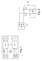
- the coupling network CN is designed as a so-called two-port or as a so-called quadrupole ( FIG. 2 ).
- a first gate is formed by a two-port input.
- the input is parallel to the first antenna LF1, which is shown in the equivalent circuit diagram as a parallel connection of a coil L1 and a capacitor C1.
- the output forming the second gate is connected to the second integrated circuit IC2 (not in FIG FIG. 2 shown).
- a series connection of a first resistance element R1 and a first capacitor C2 is provided between a first terminal of the input and a first terminal of the output.
- a same series connection of a second resistance element R2 and a second capacitor C3 is provided.
- the first resistance element R1 and the second resistance element R2 have a same electrical resistance.
- the first capacitor C2 and the second capacitor C3 have a same capacity.
- Parallel to the output of the coupling network CN a third resistance element R3 is connected.
Landscapes
- Engineering & Computer Science (AREA)
- Mechanical Engineering (AREA)
- Physics & Mathematics (AREA)
- General Physics & Mathematics (AREA)
- Manufacturing & Machinery (AREA)
- Human Computer Interaction (AREA)
- Lock And Its Accessories (AREA)
Priority Applications (1)
| Application Number | Priority Date | Filing Date | Title |
|---|---|---|---|
| EP08169940A EP2192009B1 (fr) | 2008-11-26 | 2008-11-26 | Dispositif d'identification pour un système d'accès électronique et un dispositif d'immobilisation électronique |
Applications Claiming Priority (1)
| Application Number | Priority Date | Filing Date | Title |
|---|---|---|---|
| EP08169940A EP2192009B1 (fr) | 2008-11-26 | 2008-11-26 | Dispositif d'identification pour un système d'accès électronique et un dispositif d'immobilisation électronique |
Publications (2)
| Publication Number | Publication Date |
|---|---|
| EP2192009A1 true EP2192009A1 (fr) | 2010-06-02 |
| EP2192009B1 EP2192009B1 (fr) | 2012-05-30 |
Family
ID=40666939
Family Applications (1)
| Application Number | Title | Priority Date | Filing Date |
|---|---|---|---|
| EP08169940A Active EP2192009B1 (fr) | 2008-11-26 | 2008-11-26 | Dispositif d'identification pour un système d'accès électronique et un dispositif d'immobilisation électronique |
Country Status (1)
| Country | Link |
|---|---|
| EP (1) | EP2192009B1 (fr) |
Citations (5)
| Publication number | Priority date | Publication date | Assignee | Title |
|---|---|---|---|---|
| EP1201514A1 (fr) * | 2000-04-26 | 2002-05-02 | Kabushiki Kaisha Tokai Rika Denki Seisakusho | Telecommande de vehicule |
| DE102005015594A1 (de) | 2005-04-05 | 2006-10-19 | Texas Instruments Deutschland Gmbh | Berührungsloses Zugangssystem und Wegfahrsperre mit unterschiedlichen Frequenzen unter Verwendung derselben Antennenspule |
| KR100769540B1 (ko) * | 2006-10-09 | 2007-10-23 | 충북대학교 산학협력단 | 무선식별 태그와 리더의 이중 구조를 갖는 루프형 안테나및 그를 이용한 근거리통신 송수신 시스템 |
| DE102006020422A1 (de) * | 2006-04-25 | 2007-10-31 | Atmel Germany Gmbh | Passive-Entry- und/oder Passive-Go-System sowie zugehöriges Betriebsverfahren |
| DE102007037491A1 (de) * | 2006-08-21 | 2008-03-27 | Denso Corp., Kariya | Funkschlüssel und Tür-Fernsteuersystem |
-
2008
- 2008-11-26 EP EP08169940A patent/EP2192009B1/fr active Active
Patent Citations (5)
| Publication number | Priority date | Publication date | Assignee | Title |
|---|---|---|---|---|
| EP1201514A1 (fr) * | 2000-04-26 | 2002-05-02 | Kabushiki Kaisha Tokai Rika Denki Seisakusho | Telecommande de vehicule |
| DE102005015594A1 (de) | 2005-04-05 | 2006-10-19 | Texas Instruments Deutschland Gmbh | Berührungsloses Zugangssystem und Wegfahrsperre mit unterschiedlichen Frequenzen unter Verwendung derselben Antennenspule |
| DE102006020422A1 (de) * | 2006-04-25 | 2007-10-31 | Atmel Germany Gmbh | Passive-Entry- und/oder Passive-Go-System sowie zugehöriges Betriebsverfahren |
| DE102007037491A1 (de) * | 2006-08-21 | 2008-03-27 | Denso Corp., Kariya | Funkschlüssel und Tür-Fernsteuersystem |
| KR100769540B1 (ko) * | 2006-10-09 | 2007-10-23 | 충북대학교 산학협력단 | 무선식별 태그와 리더의 이중 구조를 갖는 루프형 안테나및 그를 이용한 근거리통신 송수신 시스템 |
Also Published As
| Publication number | Publication date |
|---|---|
| EP2192009B1 (fr) | 2012-05-30 |
Similar Documents
| Publication | Publication Date | Title |
|---|---|---|
| DE102013101768A1 (de) | Transformator und elektrische Schaltung | |
| DE102011087116A1 (de) | Frequenzvervielfacher | |
| DE102016105359B4 (de) | Serieller Kapazitätstuner | |
| DE102005037579B4 (de) | Elektronische Steuereinheit | |
| EP2003659A1 (fr) | Induction monolithique intégrée | |
| DE112020001876T5 (de) | Elektronische Einrichtung | |
| EP3824561B1 (fr) | Dispositif pour un véhicule destiné à transmettre des données sans contact | |
| EP3462612A1 (fr) | Circuit d'antenne pour antennes de champ proche | |
| DE102005023234B4 (de) | Vorrichtungen und Verfahren zur Reduzierung der Strahlungsemission elektronischer Baugruppen | |
| EP2192009B1 (fr) | Dispositif d'identification pour un système d'accès électronique et un dispositif d'immobilisation électronique | |
| DE19635175A1 (de) | Telekommunikationsgerät mit als Ringschaltung ausgeführter Schaltvorrichtung | |
| DE102019134068A1 (de) | Hochfrequenzanpassungsvorrichtung für einen Reifendrucksensor | |
| WO2023148207A1 (fr) | Mélangeur électro-optique | |
| DE102018109540A1 (de) | Spule sowie Einrichtung zur drahtlosen Signalübertragung sowie ein Verfahren zur Herstellung einer derartigen Spule | |
| EP2178155B1 (fr) | Coupleur directif doté d'une compensation de la netteté d'orientation par adaptation ciblée des erreurs | |
| DE102008044845B4 (de) | Bias-Netzwerk | |
| DE112021005226T5 (de) | Elektronische steuervorrichtung | |
| DE60123091T2 (de) | Tragbarer Empfänger mit zwei Antennen | |
| DE102010062462A1 (de) | Antennensystem, Sendeanordnung und Verfahren zum Betrieb einer Sendeanordnung | |
| WO2009000434A1 (fr) | Coupleur orienté à netteté d'orientation compensée inductivement | |
| DE102017218623A1 (de) | Antennenmodul für ein RFID-Lesegerät | |
| DE102004027839A1 (de) | Antennenstruktur | |
| DE102008048107A1 (de) | Flexible Antennendiagnose für integrierte Scheibenantennen am Heizfeld | |
| DE102018211016A1 (de) | Schaltung zur signaltechnischen Verbindung, Vorrichtung zur induktiven Übertragung von Energie sowie zur Signalübertragung sowie Verfahren zur Herstellung | |
| DE102004038837A1 (de) | Elektronisches Diebstahlschutzsystem mit korrelierten Sende-/Empfangsantennen |
Legal Events
| Date | Code | Title | Description |
|---|---|---|---|
| PUAI | Public reference made under article 153(3) epc to a published international application that has entered the european phase |
Free format text: ORIGINAL CODE: 0009012 |
|
| AK | Designated contracting states |
Kind code of ref document: A1 Designated state(s): AT BE BG CH CY CZ DE DK EE ES FI FR GB GR HR HU IE IS IT LI LT LU LV MC MT NL NO PL PT RO SE SI SK TR |
|
| AX | Request for extension of the european patent |
Extension state: AL BA MK RS |
|
| 17P | Request for examination filed |
Effective date: 20101116 |
|
| 17Q | First examination report despatched |
Effective date: 20101229 |
|
| AKX | Designation fees paid |
Designated state(s): AT BE BG CH CY CZ DE DK EE ES FI FR GB GR HR HU IE IS IT LI LT LU LV MC MT NL NO PL PT RO SE SI SK TR |
|
| GRAP | Despatch of communication of intention to grant a patent |
Free format text: ORIGINAL CODE: EPIDOSNIGR1 |
|
| GRAS | Grant fee paid |
Free format text: ORIGINAL CODE: EPIDOSNIGR3 |
|
| GRAA | (expected) grant |
Free format text: ORIGINAL CODE: 0009210 |
|
| AK | Designated contracting states |
Kind code of ref document: B1 Designated state(s): AT BE BG CH CY CZ DE DK EE ES FI FR GB GR HR HU IE IS IT LI LT LU LV MC MT NL NO PL PT RO SE SI SK TR |
|
| REG | Reference to a national code |
Ref country code: GB Ref legal event code: FG4D Free format text: NOT ENGLISH |
|
| REG | Reference to a national code |
Ref country code: CH Ref legal event code: EP |
|
| REG | Reference to a national code |
Ref country code: AT Ref legal event code: REF Ref document number: 559922 Country of ref document: AT Kind code of ref document: T Effective date: 20120615 |
|
| REG | Reference to a national code |
Ref country code: IE Ref legal event code: FG4D Free format text: LANGUAGE OF EP DOCUMENT: GERMAN |
|
| REG | Reference to a national code |
Ref country code: DE Ref legal event code: R096 Ref document number: 502008007308 Country of ref document: DE Effective date: 20120726 |
|
| REG | Reference to a national code |
Ref country code: NL Ref legal event code: VDEP Effective date: 20120530 |
|
| REG | Reference to a national code |
Ref country code: LT Ref legal event code: MG4D Effective date: 20120523 |
|
| PG25 | Lapsed in a contracting state [announced via postgrant information from national office to epo] |
Ref country code: SE Free format text: LAPSE BECAUSE OF FAILURE TO SUBMIT A TRANSLATION OF THE DESCRIPTION OR TO PAY THE FEE WITHIN THE PRESCRIBED TIME-LIMIT Effective date: 20120530 Ref country code: CY Free format text: LAPSE BECAUSE OF FAILURE TO SUBMIT A TRANSLATION OF THE DESCRIPTION OR TO PAY THE FEE WITHIN THE PRESCRIBED TIME-LIMIT Effective date: 20120530 Ref country code: NO Free format text: LAPSE BECAUSE OF FAILURE TO SUBMIT A TRANSLATION OF THE DESCRIPTION OR TO PAY THE FEE WITHIN THE PRESCRIBED TIME-LIMIT Effective date: 20120830 Ref country code: IS Free format text: LAPSE BECAUSE OF FAILURE TO SUBMIT A TRANSLATION OF THE DESCRIPTION OR TO PAY THE FEE WITHIN THE PRESCRIBED TIME-LIMIT Effective date: 20120930 Ref country code: FI Free format text: LAPSE BECAUSE OF FAILURE TO SUBMIT A TRANSLATION OF THE DESCRIPTION OR TO PAY THE FEE WITHIN THE PRESCRIBED TIME-LIMIT Effective date: 20120530 Ref country code: LT Free format text: LAPSE BECAUSE OF FAILURE TO SUBMIT A TRANSLATION OF THE DESCRIPTION OR TO PAY THE FEE WITHIN THE PRESCRIBED TIME-LIMIT Effective date: 20120530 |
|
| PG25 | Lapsed in a contracting state [announced via postgrant information from national office to epo] |
Ref country code: GR Free format text: LAPSE BECAUSE OF FAILURE TO SUBMIT A TRANSLATION OF THE DESCRIPTION OR TO PAY THE FEE WITHIN THE PRESCRIBED TIME-LIMIT Effective date: 20120831 Ref country code: HR Free format text: LAPSE BECAUSE OF FAILURE TO SUBMIT A TRANSLATION OF THE DESCRIPTION OR TO PAY THE FEE WITHIN THE PRESCRIBED TIME-LIMIT Effective date: 20120530 Ref country code: SI Free format text: LAPSE BECAUSE OF FAILURE TO SUBMIT A TRANSLATION OF THE DESCRIPTION OR TO PAY THE FEE WITHIN THE PRESCRIBED TIME-LIMIT Effective date: 20120530 Ref country code: LV Free format text: LAPSE BECAUSE OF FAILURE TO SUBMIT A TRANSLATION OF THE DESCRIPTION OR TO PAY THE FEE WITHIN THE PRESCRIBED TIME-LIMIT Effective date: 20120530 |
|
| PG25 | Lapsed in a contracting state [announced via postgrant information from national office to epo] |
Ref country code: CZ Free format text: LAPSE BECAUSE OF FAILURE TO SUBMIT A TRANSLATION OF THE DESCRIPTION OR TO PAY THE FEE WITHIN THE PRESCRIBED TIME-LIMIT Effective date: 20120530 Ref country code: RO Free format text: LAPSE BECAUSE OF FAILURE TO SUBMIT A TRANSLATION OF THE DESCRIPTION OR TO PAY THE FEE WITHIN THE PRESCRIBED TIME-LIMIT Effective date: 20120530 Ref country code: EE Free format text: LAPSE BECAUSE OF FAILURE TO SUBMIT A TRANSLATION OF THE DESCRIPTION OR TO PAY THE FEE WITHIN THE PRESCRIBED TIME-LIMIT Effective date: 20120530 Ref country code: SK Free format text: LAPSE BECAUSE OF FAILURE TO SUBMIT A TRANSLATION OF THE DESCRIPTION OR TO PAY THE FEE WITHIN THE PRESCRIBED TIME-LIMIT Effective date: 20120530 Ref country code: DK Free format text: LAPSE BECAUSE OF FAILURE TO SUBMIT A TRANSLATION OF THE DESCRIPTION OR TO PAY THE FEE WITHIN THE PRESCRIBED TIME-LIMIT Effective date: 20120530 Ref country code: NL Free format text: LAPSE BECAUSE OF FAILURE TO SUBMIT A TRANSLATION OF THE DESCRIPTION OR TO PAY THE FEE WITHIN THE PRESCRIBED TIME-LIMIT Effective date: 20120530 |
|
| PG25 | Lapsed in a contracting state [announced via postgrant information from national office to epo] |
Ref country code: IT Free format text: LAPSE BECAUSE OF FAILURE TO SUBMIT A TRANSLATION OF THE DESCRIPTION OR TO PAY THE FEE WITHIN THE PRESCRIBED TIME-LIMIT Effective date: 20120530 Ref country code: PL Free format text: LAPSE BECAUSE OF FAILURE TO SUBMIT A TRANSLATION OF THE DESCRIPTION OR TO PAY THE FEE WITHIN THE PRESCRIBED TIME-LIMIT Effective date: 20120530 Ref country code: PT Free format text: LAPSE BECAUSE OF FAILURE TO SUBMIT A TRANSLATION OF THE DESCRIPTION OR TO PAY THE FEE WITHIN THE PRESCRIBED TIME-LIMIT Effective date: 20121001 |
|
| PLBE | No opposition filed within time limit |
Free format text: ORIGINAL CODE: 0009261 |
|
| STAA | Information on the status of an ep patent application or granted ep patent |
Free format text: STATUS: NO OPPOSITION FILED WITHIN TIME LIMIT |
|
| PG25 | Lapsed in a contracting state [announced via postgrant information from national office to epo] |
Ref country code: ES Free format text: LAPSE BECAUSE OF FAILURE TO SUBMIT A TRANSLATION OF THE DESCRIPTION OR TO PAY THE FEE WITHIN THE PRESCRIBED TIME-LIMIT Effective date: 20120910 |
|
| 26N | No opposition filed |
Effective date: 20130301 |
|
| BERE | Be: lapsed |
Owner name: HELLA KGAA HUECK & CO. Effective date: 20121130 |
|
| REG | Reference to a national code |
Ref country code: CH Ref legal event code: PL |
|
| REG | Reference to a national code |
Ref country code: DE Ref legal event code: R097 Ref document number: 502008007308 Country of ref document: DE Effective date: 20130301 |
|
| PG25 | Lapsed in a contracting state [announced via postgrant information from national office to epo] |
Ref country code: BG Free format text: LAPSE BECAUSE OF FAILURE TO SUBMIT A TRANSLATION OF THE DESCRIPTION OR TO PAY THE FEE WITHIN THE PRESCRIBED TIME-LIMIT Effective date: 20120830 Ref country code: LI Free format text: LAPSE BECAUSE OF NON-PAYMENT OF DUE FEES Effective date: 20121130 Ref country code: CH Free format text: LAPSE BECAUSE OF NON-PAYMENT OF DUE FEES Effective date: 20121130 |
|
| REG | Reference to a national code |
Ref country code: IE Ref legal event code: MM4A |
|
| PG25 | Lapsed in a contracting state [announced via postgrant information from national office to epo] |
Ref country code: BE Free format text: LAPSE BECAUSE OF NON-PAYMENT OF DUE FEES Effective date: 20121130 |
|
| PG25 | Lapsed in a contracting state [announced via postgrant information from national office to epo] |
Ref country code: IE Free format text: LAPSE BECAUSE OF NON-PAYMENT OF DUE FEES Effective date: 20121126 |
|
| PG25 | Lapsed in a contracting state [announced via postgrant information from national office to epo] |
Ref country code: MT Free format text: LAPSE BECAUSE OF FAILURE TO SUBMIT A TRANSLATION OF THE DESCRIPTION OR TO PAY THE FEE WITHIN THE PRESCRIBED TIME-LIMIT Effective date: 20120530 |
|
| PG25 | Lapsed in a contracting state [announced via postgrant information from national office to epo] |
Ref country code: TR Free format text: LAPSE BECAUSE OF FAILURE TO SUBMIT A TRANSLATION OF THE DESCRIPTION OR TO PAY THE FEE WITHIN THE PRESCRIBED TIME-LIMIT Effective date: 20120530 Ref country code: MC Free format text: LAPSE BECAUSE OF NON-PAYMENT OF DUE FEES Effective date: 20121130 |
|
| PG25 | Lapsed in a contracting state [announced via postgrant information from national office to epo] |
Ref country code: LU Free format text: LAPSE BECAUSE OF NON-PAYMENT OF DUE FEES Effective date: 20121126 |
|
| PG25 | Lapsed in a contracting state [announced via postgrant information from national office to epo] |
Ref country code: HU Free format text: LAPSE BECAUSE OF FAILURE TO SUBMIT A TRANSLATION OF THE DESCRIPTION OR TO PAY THE FEE WITHIN THE PRESCRIBED TIME-LIMIT Effective date: 20081126 |
|
| REG | Reference to a national code |
Ref country code: AT Ref legal event code: MM01 Ref document number: 559922 Country of ref document: AT Kind code of ref document: T Effective date: 20131126 |
|
| PG25 | Lapsed in a contracting state [announced via postgrant information from national office to epo] |
Ref country code: AT Free format text: LAPSE BECAUSE OF NON-PAYMENT OF DUE FEES Effective date: 20131126 |
|
| REG | Reference to a national code |
Ref country code: FR Ref legal event code: PLFP Year of fee payment: 8 |
|
| REG | Reference to a national code |
Ref country code: FR Ref legal event code: PLFP Year of fee payment: 9 |
|
| REG | Reference to a national code |
Ref country code: FR Ref legal event code: PLFP Year of fee payment: 10 |
|
| REG | Reference to a national code |
Ref country code: DE Ref legal event code: R081 Ref document number: 502008007308 Country of ref document: DE Owner name: HELLA GMBH & CO. KGAA, DE Free format text: FORMER OWNER: HELLA KGAA HUECK & CO., 59557 LIPPSTADT, DE |
|
| REG | Reference to a national code |
Ref country code: FR Ref legal event code: PLFP Year of fee payment: 11 |
|
| PGFP | Annual fee paid to national office [announced via postgrant information from national office to epo] |
Ref country code: ES Payment date: 20181203 Year of fee payment: 8 |
|
| GBPC | Gb: european patent ceased through non-payment of renewal fee |
Effective date: 20191126 |
|
| PG25 | Lapsed in a contracting state [announced via postgrant information from national office to epo] |
Ref country code: GB Free format text: LAPSE BECAUSE OF NON-PAYMENT OF DUE FEES Effective date: 20191126 |
|
| REG | Reference to a national code |
Ref country code: DE Ref legal event code: R084 Ref document number: 502008007308 Country of ref document: DE |
|
| PGFP | Annual fee paid to national office [announced via postgrant information from national office to epo] |
Ref country code: FR Payment date: 20250930 Year of fee payment: 18 |
|
| PGFP | Annual fee paid to national office [announced via postgrant information from national office to epo] |
Ref country code: DE Payment date: 20250930 Year of fee payment: 18 |