EP2192308A2 - Procédé et dispositif de réglage d'admission de fluide pour un actionneur hydraulique - Google Patents
Procédé et dispositif de réglage d'admission de fluide pour un actionneur hydraulique Download PDFInfo
- Publication number
- EP2192308A2 EP2192308A2 EP09014790A EP09014790A EP2192308A2 EP 2192308 A2 EP2192308 A2 EP 2192308A2 EP 09014790 A EP09014790 A EP 09014790A EP 09014790 A EP09014790 A EP 09014790A EP 2192308 A2 EP2192308 A2 EP 2192308A2
- Authority
- EP
- European Patent Office
- Prior art keywords
- pressure
- speed
- control
- signal
- coefficient
- Prior art date
- Legal status (The legal status is an assumption and is not a legal conclusion. Google has not performed a legal analysis and makes no representation as to the accuracy of the status listed.)
- Granted
Links
Images

Classifications
-
- F—MECHANICAL ENGINEERING; LIGHTING; HEATING; WEAPONS; BLASTING
- F15—FLUID-PRESSURE ACTUATORS; HYDRAULICS OR PNEUMATICS IN GENERAL
- F15B—SYSTEMS ACTING BY MEANS OF FLUIDS IN GENERAL; FLUID-PRESSURE ACTUATORS, e.g. SERVOMOTORS; DETAILS OF FLUID-PRESSURE SYSTEMS, NOT OTHERWISE PROVIDED FOR
- F15B11/00—Servomotor systems without provision for follow-up action; Circuits therefor
- F15B11/02—Systems essentially incorporating special features for controlling the speed or actuating force of an output member
-
- F—MECHANICAL ENGINEERING; LIGHTING; HEATING; WEAPONS; BLASTING
- F15—FLUID-PRESSURE ACTUATORS; HYDRAULICS OR PNEUMATICS IN GENERAL
- F15B—SYSTEMS ACTING BY MEANS OF FLUIDS IN GENERAL; FLUID-PRESSURE ACTUATORS, e.g. SERVOMOTORS; DETAILS OF FLUID-PRESSURE SYSTEMS, NOT OTHERWISE PROVIDED FOR
- F15B9/00—Servomotors with follow-up action, e.g. obtained by feed-back control, i.e. in which the position of the actuated member conforms with that of the controlling member
- F15B9/02—Servomotors with follow-up action, e.g. obtained by feed-back control, i.e. in which the position of the actuated member conforms with that of the controlling member with servomotors of the reciprocatable or oscillatable type
- F15B9/04—Servomotors with follow-up action, e.g. obtained by feed-back control, i.e. in which the position of the actuated member conforms with that of the controlling member with servomotors of the reciprocatable or oscillatable type controlled by varying the output of a pump with variable capacity
-
- F—MECHANICAL ENGINEERING; LIGHTING; HEATING; WEAPONS; BLASTING
- F15—FLUID-PRESSURE ACTUATORS; HYDRAULICS OR PNEUMATICS IN GENERAL
- F15B—SYSTEMS ACTING BY MEANS OF FLUIDS IN GENERAL; FLUID-PRESSURE ACTUATORS, e.g. SERVOMOTORS; DETAILS OF FLUID-PRESSURE SYSTEMS, NOT OTHERWISE PROVIDED FOR
- F15B2211/00—Circuits for servomotor systems
- F15B2211/20—Fluid pressure source, e.g. accumulator or variable axial piston pump
- F15B2211/205—Systems with pumps
- F15B2211/20507—Type of prime mover
- F15B2211/20515—Electric motor
-
- F—MECHANICAL ENGINEERING; LIGHTING; HEATING; WEAPONS; BLASTING
- F15—FLUID-PRESSURE ACTUATORS; HYDRAULICS OR PNEUMATICS IN GENERAL
- F15B—SYSTEMS ACTING BY MEANS OF FLUIDS IN GENERAL; FLUID-PRESSURE ACTUATORS, e.g. SERVOMOTORS; DETAILS OF FLUID-PRESSURE SYSTEMS, NOT OTHERWISE PROVIDED FOR
- F15B2211/00—Circuits for servomotor systems
- F15B2211/20—Fluid pressure source, e.g. accumulator or variable axial piston pump
- F15B2211/205—Systems with pumps
- F15B2211/2053—Type of pump
- F15B2211/20546—Type of pump variable capacity
-
- F—MECHANICAL ENGINEERING; LIGHTING; HEATING; WEAPONS; BLASTING
- F15—FLUID-PRESSURE ACTUATORS; HYDRAULICS OR PNEUMATICS IN GENERAL
- F15B—SYSTEMS ACTING BY MEANS OF FLUIDS IN GENERAL; FLUID-PRESSURE ACTUATORS, e.g. SERVOMOTORS; DETAILS OF FLUID-PRESSURE SYSTEMS, NOT OTHERWISE PROVIDED FOR
- F15B2211/00—Circuits for servomotor systems
- F15B2211/60—Circuit components or control therefor
- F15B2211/63—Electronic controllers
- F15B2211/6303—Electronic controllers using input signals
- F15B2211/6306—Electronic controllers using input signals representing a pressure
- F15B2211/6309—Electronic controllers using input signals representing a pressure the pressure being a pressure source supply pressure
-
- F—MECHANICAL ENGINEERING; LIGHTING; HEATING; WEAPONS; BLASTING
- F15—FLUID-PRESSURE ACTUATORS; HYDRAULICS OR PNEUMATICS IN GENERAL
- F15B—SYSTEMS ACTING BY MEANS OF FLUIDS IN GENERAL; FLUID-PRESSURE ACTUATORS, e.g. SERVOMOTORS; DETAILS OF FLUID-PRESSURE SYSTEMS, NOT OTHERWISE PROVIDED FOR
- F15B2211/00—Circuits for servomotor systems
- F15B2211/60—Circuit components or control therefor
- F15B2211/63—Electronic controllers
- F15B2211/6303—Electronic controllers using input signals
- F15B2211/6333—Electronic controllers using input signals representing a state of the pressure source, e.g. swash plate angle
-
- F—MECHANICAL ENGINEERING; LIGHTING; HEATING; WEAPONS; BLASTING
- F15—FLUID-PRESSURE ACTUATORS; HYDRAULICS OR PNEUMATICS IN GENERAL
- F15B—SYSTEMS ACTING BY MEANS OF FLUIDS IN GENERAL; FLUID-PRESSURE ACTUATORS, e.g. SERVOMOTORS; DETAILS OF FLUID-PRESSURE SYSTEMS, NOT OTHERWISE PROVIDED FOR
- F15B2211/00—Circuits for servomotor systems
- F15B2211/60—Circuit components or control therefor
- F15B2211/665—Methods of control using electronic components
- F15B2211/6656—Closed loop control, i.e. control using feedback
Definitions
- the invention relates to a method and a control device for controlling a pressure medium supply for a hydraulic actuator.
- an electric motor drives a pump, which supplies the cylinder with a hydraulic pressure medium according to a pressure / volume flow control.
- a pump which supplies the cylinder with a hydraulic pressure medium according to a pressure / volume flow control.
- a method for controlling a pressure medium supply for a hydraulic actuator of a -z.B. cyclic working - machine provided.
- the actuator is supplied by a variable displacement pump with a pressure medium quantity, wherein the variable displacement pump in turn by a speed-controlled motor -. an electric motor - is driven.
- a signal indicative of the pressure of the pressure medium quantity is fed back to a regulator for driving the variable displacement pump.
- the controller has a comparator and a control amplifier. Parallel to this pressure control circuit, the motor is driven by a speed signal.
- a speed profile for adjusting the speed of the electric motor can be created within a work cycle of the machine to form the speed signal, as is the case EP 1 236 558 B1 describes.
- the electric motor is operated according to the determined speed profile. But it can also be a speed signal from a higher-level control loop or an external control can be specified.
- the properties of the regulator amplifier of the pressure regulator are varied according to the speed signal.
- the control quality of the controller can be left constant at different speeds. As a result, the deterioration of the control quality can be counteracted at reduced speed. Without the corresponding variation of the characteristics of the control amplifiers, the loop gain would also decrease at reduced speed. This may increase a permanent control deviation, or the damping of the control loop will be worse, causing disturbances that affect the control loop, more noticeable. By varying the characteristics of the control amplifier this is counteracted.
- the gain of the variable gain amplifier is adjusted as a function of the rotational speed. With a change in the gain of the control amplifier and the loop gain is changed, whereby this can be kept substantially constant even at different speeds.
- the gain of the variable gain amplifier is increased to leave the loop gain substantially constant.
- disturbances at low speed do not lead to a much larger control deviation than at high speed.
- the pressure regulator has a differentiating element with a coefficient KD for differentiating the signal, which indicates the pressure of the pressure medium quantity.
- the coefficient KD of the differentiating element is set as a function of the rotational speed.
- the coefficient of the differentiator is set to higher values to counteract a drop in damping at low speeds.
- the method is particularly suitable in a plastic processing machine in which liquid plastic is injected into a mold.
- Other applications may be presses, in particular press brakes. In such machines, the same operations are often repeated so that the pressure medium requirement is the same for each working cycle.
- the invention also relates to a control device for controlling a pressure medium supply for a hydraulic actuator of a - eg cyclically operating - machine.
- the actuator of one of a speed-controlled motor - for example, an electric motor, possibly, for example, an internal combustion engine, a diesel engine, a gasoline engine - powered variable displacement pump supplied with a pressure medium.
- the pressure regulator for driving the variable displacement pump and a pressure transducer for converting the pressure of the pressure medium quantity into a feedback signal for the pressure regulator are provided.
- the control device may also include a device for establishing a speed profile for adjusting the speed of the motor during a cycle of the machine and an adjuster for operating the motor according to the determined speed profile in the working cycles of the machine.
- the speed of the motor can also be controlled and adjusted by means of a control device supplied speed signal.
- the control device includes a control adjustment device for adjusting the characteristics of the pressure regulator in accordance with the speed signal. The control device thus makes it possible to leave the control quality substantially constant over a large speed range.
- the pressure regulator comprises a comparator and a variable gain control amplifier, wherein the gain of the variable gain amplifier is adjusted in response to the speed signal. This adjusts the loop gain and thus also the control deviation. Preferably, the gain of the control amplifier is increased when reducing the speed.
- the pressure regulator has a differentiating element with a coefficient KD for differentiating that signal which indicates the pressure of the pressure medium quantity.
- the control adjusting device is set to adjust the coefficient of the differentiating element in response to the rotational speed signal.
- the coefficient KD of the differentiator is set to higher values.
- the invention also relates to an assembly of a control device according to the invention and an actuator whose supply is provided with a hydraulic pressure by means of the control device.
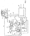
- FIG. 1 shows an actuator of a production machine and the control used to provide hydraulic pressure means for this actuator.
- Actuator 11 is a cylinder for a cyclical manufacturing machine that injects liquid plastic into a mold.
- a duty cycle is divided into several consecutive sections of the cycle, which differ in terms of the required amount of pressure. Each of these sections is a work process. Operations include, for example, "close tool”, “inject plastic”, “open the tool”, “wait for a hold phase”, or the like.
- variable displacement pump 13 conveys pressure medium into the line 16 from a tank 15, whereupon the hydraulic fluid in the line 16 has a pressure p.
- the valve 17 is provided between the conduit 16 and the actuator 11. This valve 17 controls the volume flow from the variable displacement pump 13 to the cylinder 11 and from there back to the tank 15.
- the valve 17 is electrically controlled by a higher-level control 25 with the signal u1, which is conducted via the line 27.
- a Wegemessumformer 21 measures the position of the piston rod of the cylinder 11, converts this position into an electrical signal s1, which is output via the line 23 to the higher-level controller 25.
- a control device which includes the means for controlling the pressure medium supply 10, the pressure transducer 40, the actuator 31, the transmitter 32, the frequency converter 33, the electric motor 14, the shaft 34 and the variable displacement pump 13 contains.
- the device 10 receives from the higher-level controller 25 a setpoint for the pressure ps and a setpoint for the volume flow Qs.
- the setpoints ps and Qs correspond to a pressure volumetric flow profile P (t) / Q (t) stored in the higher-level controller.
- the device 10 receives a cycle start signal yt0 indicating when a new cycle begins.
- the device 10 receives the signal pi from the pressure transducer 40, which converts the pressure p in the line 16 into a corresponding electrical signal pi.
- the device 10 outputs a desired value for the rotational speed ns and an output signal for the delivery volume yVF.
- the signal ns receives the frequency converter 33, which accordingly drives the electric motor 14 at a frequency f such that the rotational speed n of the electric motor 14 is equal to the target value for the rotational speed ns.
- the rotational movement of the electric motor is transmitted via the shaft 34 to the variable displacement pump 13.
- the speed n of the electric motor 14 is not measured and fed back, the speed n is thus controlled in the open circuit.
- the actuator 31 receives the output signal yVF from the device 10 and controls the delivery volume VF of the variable displacement pump 13.
- the transducer 32 outputs an electrical signal indicative of the actual value of the delivery volume VFi of the variable displacement pump 13.
- the device 10 includes a pump controller 41, a motor controller 42, a multiplier 44, and a calculator 45.
- the multiplier 44 is implemented as a proportional element with a controllable gain KQ.
- the arithmetic unit 45 receives as an input signal the setpoint value for the speed ns and outputs its reciprocal value to its output as the signal KQ.
- the multiplier receives at its inputs the setpoint for the volume flow QS and the signal KQ.
- the multiplier 44 thus forms from the desired value QS for the volume flow to be supplied to the cylinder, taking into account the rotational speed n of the electric motor 14, a target value VFs for the delivery volume of the variable displacement pump 13.
- the pump regulator 41 receives as input the actual value for the delivery volume VFi, the actual Value for the pressure pi, the setpoint for the delivery volume VFs and the setpoint for the pressure ps and outputs at its output the output signal for the delivery volume yVF.
- FIG. 2 shows details of the pump controller 41 FIG. 1 ,
- the pressure regulator 41 has a first summation element 48, a second summation element 51, a delivery volume regulator 49, a pressure regulator 52 and a minimum value selection element 50.
- the first summation element 48 forms from the desired value VFs and the actual value VFi a control difference, which is supplied to the delivery volume controller 49 as an input signal.
- the output signal of the delivery volume controller 49 is added to the minimum value selection element 50 as the first input signal.
- the second summation element 51 receives the desired value for the pressure ps and the actual value for the pressure pi, from which the control difference for the pressure is formed by subtraction and output to the pressure regulator 52.
- the pressure regulator 52 outputs as an output the value yp to the minimum value selector 50 which receives the value yp at its second input.
- the minimum value selector element 50 selects the smaller of the two input signals yVF1 and yp and forwards this minimum value as manipulated variable yVF for the delivery volume VF to the actuator 31. Both the regulation of the delivery volume VF and the regulation of the pressure p takes place with the aid of adjusting the delivery volume of the variable displacement pump 13.
- the transmission characteristics of the delivery flow regulator 49 and the pressure regulator 52 each have a proportional and a differential component.
- a pressure / volume flow profile p (t) / Q (t) for the pressure medium supply of the cylinder 11 is stored.
- a speed profile n (t) for the electric motor is as in the document EP 1 236 558 B1 created.
- a speed profile n (t) is created for the electric motor 14, which specifies the course of the rotational speed n during a production cycle.
- the electric motor 14 is first operated at the constant speed nmax.
- the control of the cylinder 11 supplied volume flow is carried out solely by the pump controller 41.
- the pump controller 41 ensures that the variable displacement pump 13 to the cylinder 11, the volume flow which is required to the by the pressure / flow profile p (t) / Q (t) specified values. This volume flow is also referred to below as the volume flow requirement QA.
- nmax the highest speed with which the electric motor 14 is to be operated in the production cycles. This speed is usually the rated speed of the electric motor 14th
- the optimization process has a series of learning cycles in which the variable displacement pump 13 is driven at the constant speed nmax.
- a first learning cycle the duration of a manufacturing cycle is determined by measuring the time between two cycle start pulses. From the duration of a production cycle and the number of memory locations available in the motor controller 42 for storing values, the time interval ⁇ t for the detection of the values to be stored is determined.
- the actual values VFi of the delivery volume are detected at a distance of ⁇ t and stored in the engine control unit 42. The values stored there form a delivery volume profile VFI (t).
- the actual values pi of the pressure are detected and stored in the engine controller 42.
- the stored values form a pressure profile pi (t).
- a volume flow demand profile QA (t) is obtained.
- a speed profile n (t) is obtained. It is advisable to choose the constant value so that it is close to the nominal value of the delivery volume VF of the variable displacement pump 13.
- the constant value is chosen such that it corresponds to approximately 90% of the nominal value of the delivery volume VF of the variable displacement pump 13. This value is denoted below by VFgO.
- the stored value of the volume flow demand QA can be replaced by the speed value n calculated from it. If one controls the speed of the electric motor 14 in accordance with the speed profile n (t) determined in this way, the delivery volume VF of the variable displacement pump 13 would adjust to the value VFgO under ideal conditions. In practice, however, the delivery volume VF of the variable displacement pump 13 is not constant during a cycle, in particular because the speed n of the electric motor 14 can not be changed as fast as the delivery volume VF of the variable displacement pump 13. In addition, in particular with regard to the lubrication of Variable 13, the cooling of the electric motor 14 and the maximum torque of the electric motor 14 its speed n may not be arbitrarily reduced.
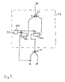
- FIG. 3 shows details of the pressure regulator 52 in a schematic overview.
- the pressure regulator 52 includes a differentiating member 521, a proportional member 522, a summing member 524, and an adjusting block 523.
- the proportional member 522 receives the control difference for the pressure from the second summing member 51 of the pressure regulator 41. This control difference is multiplied by the coefficient Kp and the result of this Multiplication to a first input of the summation 524 out.
- the differentiator 521 receives the actual value for the pressure pi, which is derived in the differentiator 521 and multiplied by the factor KD, which is the coefficient of the differentiator 521.
- the result of this multiplication is fed to the second input of the summation element 524.
- the summer 524 subtracts the value at its second input from the value at its first input and outputs the result of this difference as the output yp.
- the adjustment block 523 receives at its input the setpoint for the speed ns and outputs at its outputs values with which the coefficients Kp and KD are varied.
- a value table is stored in the adjustment block 523, which indicates how large the factors Kp and KD are in the different value ranges of the setpoint speed ns. For example, in a speed range of 600 to 800 rpm, the factor Kp is set twice as large as in the speed range of 1300 to 1500 rpm. Accordingly, the factor KD is increased in the low speed range in comparison to the high speed range.
Landscapes
- Engineering & Computer Science (AREA)
- Physics & Mathematics (AREA)
- Fluid Mechanics (AREA)
- Mechanical Engineering (AREA)
- General Engineering & Computer Science (AREA)
- Fluid-Pressure Circuits (AREA)
Applications Claiming Priority (1)
| Application Number | Priority Date | Filing Date | Title |
|---|---|---|---|
| DE102008059659 | 2008-11-29 |
Publications (3)
| Publication Number | Publication Date |
|---|---|
| EP2192308A2 true EP2192308A2 (fr) | 2010-06-02 |
| EP2192308A3 EP2192308A3 (fr) | 2014-05-07 |
| EP2192308B1 EP2192308B1 (fr) | 2015-07-08 |
Family
ID=41786481
Family Applications (1)
| Application Number | Title | Priority Date | Filing Date |
|---|---|---|---|
| EP09014790.1A Active EP2192308B1 (fr) | 2008-11-29 | 2009-11-27 | Procédé et dispositif de réglage d'admission de fluide pour un actionneur hydraulique |
Country Status (2)
| Country | Link |
|---|---|
| EP (1) | EP2192308B1 (fr) |
| DE (1) | DE102009055979A1 (fr) |
Cited By (1)
| Publication number | Priority date | Publication date | Assignee | Title |
|---|---|---|---|---|
| CN103846152A (zh) * | 2014-03-19 | 2014-06-11 | 湖州市千金宝云机械铸件有限公司 | 立式粉碎机 |
Families Citing this family (2)
| Publication number | Priority date | Publication date | Assignee | Title |
|---|---|---|---|---|
| AT11578U1 (de) | 2010-03-26 | 2011-01-15 | Engel Austria Gmbh | Hydraulische antriebseinheit für eine spritzgiessmaschine |
| EP4381198A1 (fr) * | 2021-08-05 | 2024-06-12 | Illinois Tool Works, Inc. | Unité hydraulique pour essai de matériau |
Family Cites Families (2)
| Publication number | Priority date | Publication date | Assignee | Title |
|---|---|---|---|---|
| DE4335403C1 (de) * | 1993-10-18 | 1994-12-15 | Karl Hehl | Hydraulikeinrichtung |
| DE10110398A1 (de) * | 2001-03-03 | 2002-09-26 | Mannesmann Rexroth Ag | Verfahren zur Regelung der Druckmittelzufuhr zu einem hydraulisch betätigten Aktor |
-
2009
- 2009-11-27 DE DE102009055979A patent/DE102009055979A1/de not_active Withdrawn
- 2009-11-27 EP EP09014790.1A patent/EP2192308B1/fr active Active
Cited By (1)
| Publication number | Priority date | Publication date | Assignee | Title |
|---|---|---|---|---|
| CN103846152A (zh) * | 2014-03-19 | 2014-06-11 | 湖州市千金宝云机械铸件有限公司 | 立式粉碎机 |
Also Published As
| Publication number | Publication date |
|---|---|
| EP2192308A3 (fr) | 2014-05-07 |
| EP2192308B1 (fr) | 2015-07-08 |
| DE102009055979A1 (de) | 2010-06-02 |
Similar Documents
| Publication | Publication Date | Title |
|---|---|---|
| EP2192309B1 (fr) | Procédé et circuit de réglage destinés au réglage d'une alimentation en fluide sous pression pour un actionneur hydraulique | |
| EP1236558B1 (fr) | Methode de régulation de l'alimentation en fluide d'un actionneur hydraulique | |
| DE112018003927B4 (de) | Verfahren zur Regelung des Ausgangsdrucks eines Hydraulikantriebsystems, Verwendung des Verfahrens und Hydraulikantriebssystem | |
| EP0782671B1 (fr) | DISPOSITIF POUR l'ENTREINEMENT CONTROLE D'AU MOINS UN ARBRE HYDRAULIQUE | |
| EP0649722B1 (fr) | Dispositif hydraulique | |
| EP2929193B1 (fr) | Procédé permettant de faire fonctionner un dispositif hydraulique muni d'une pompe et d'un servomoteur, et dispositif hydraulique associé | |
| DE102009018071B4 (de) | Verfahren und Regelvorrichtung zur Regelung einer Druckmittelzufuhr für einen hydraulischen Aktor | |
| DE102011013151A1 (de) | Verfahren zur Kühlmittelversorgung, Schaltanordnung und Werkzeugmaschine | |
| DE102008019501A1 (de) | Elektrohydraulische Steueranordnung | |
| EP1930594B1 (fr) | Procédé de régulation d'une pompe hydraulique et unité de commande électronique | |
| EP2192308B1 (fr) | Procédé et dispositif de réglage d'admission de fluide pour un actionneur hydraulique | |
| EP1568874B1 (fr) | Procédé et système de commande de débit volumétrique dans un système d'injection de carburant d' un moteur à combustion interne | |
| DE102011012714A1 (de) | Hydraulische Antriebseinheit für Spritzgießmaschine | |
| DE102020213262A1 (de) | Verfahren zum Betreiben eines hydraulischen Antriebs | |
| EP4081871B1 (fr) | Procédé de commande d'un système partiellement électronique | |
| EP4426953A1 (fr) | Procédé de surveillance d'un système hydraulique | |
| DE102004048120A1 (de) | Verfahren zur Optimierung der Betriebsweise einer in einem Antriebsstrang eines Fahrzeuges integrierten hydrodynamischen Komponente | |
| AT518106B1 (de) | Hydraulische Antriebseinheit und Verfahren zum Betreiben | |
| DE102011008923B4 (de) | Verfahren zum Steuern und/oder Regeln einer Hydraulische Antriebseinheit, Hydraulische Antriebseinheit sowie Spritzgießmaschine | |
| AT394825B (de) | Steuerungseinrichtung fuer hydraulisch beaufschlagbare maschinenteile einer spritzgiessmaschine | |
| EP2593679A2 (fr) | Groupe hydraulique | |
| DE10312698A1 (de) | Einrichtung zur ablösenden Regelung von Druck und Förderstrom eines hydraulischen Druckmittels | |
| DE102024128902A1 (de) | Nahrungsmittel-Verarbeitungsmaschine | |
| DE19603251C1 (de) | Verfahren und Vorrichtung zum Betreiben des hydraulischen Betriebssystems einer Kunststoffverarbeitungsmaschine | |
| DE2900224A1 (de) | Hydraulische regeleinrichtung |
Legal Events
| Date | Code | Title | Description |
|---|---|---|---|
| PUAI | Public reference made under article 153(3) epc to a published international application that has entered the european phase |
Free format text: ORIGINAL CODE: 0009012 |
|
| AK | Designated contracting states |
Kind code of ref document: A2 Designated state(s): AT BE BG CH CY CZ DE DK EE ES FI FR GB GR HR HU IE IS IT LI LT LU LV MC MK MT NL NO PL PT RO SE SI SK SM TR |
|
| AX | Request for extension of the european patent |
Extension state: AL BA RS |
|
| PUAL | Search report despatched |
Free format text: ORIGINAL CODE: 0009013 |
|
| AK | Designated contracting states |
Kind code of ref document: A3 Designated state(s): AT BE BG CH CY CZ DE DK EE ES FI FR GB GR HR HU IE IS IT LI LT LU LV MC MK MT NL NO PL PT RO SE SI SK SM TR |
|
| AX | Request for extension of the european patent |
Extension state: AL BA RS |
|
| RIC1 | Information provided on ipc code assigned before grant |
Ipc: F15B 11/02 20060101AFI20140402BHEP Ipc: F15B 9/04 20060101ALI20140402BHEP |
|
| 17P | Request for examination filed |
Effective date: 20141107 |
|
| RBV | Designated contracting states (corrected) |
Designated state(s): AT BE BG CH CY CZ DE DK EE ES FI FR GB GR HR HU IE IS IT LI LT LU LV MC MK MT NL NO PL PT RO SE SI SK SM TR |
|
| GRAP | Despatch of communication of intention to grant a patent |
Free format text: ORIGINAL CODE: EPIDOSNIGR1 |
|
| RIC1 | Information provided on ipc code assigned before grant |
Ipc: F15B 9/04 20060101ALI20150227BHEP Ipc: F15B 11/02 20060101AFI20150227BHEP |
|
| INTG | Intention to grant announced |
Effective date: 20150325 |
|
| GRAS | Grant fee paid |
Free format text: ORIGINAL CODE: EPIDOSNIGR3 |
|
| GRAA | (expected) grant |
Free format text: ORIGINAL CODE: 0009210 |
|
| AK | Designated contracting states |
Kind code of ref document: B1 Designated state(s): AT BE BG CH CY CZ DE DK EE ES FI FR GB GR HR HU IE IS IT LI LT LU LV MC MK MT NL NO PL PT RO SE SI SK SM TR |
|
| REG | Reference to a national code |
Ref country code: GB Ref legal event code: FG4D Free format text: NOT ENGLISH |
|
| REG | Reference to a national code |
Ref country code: AT Ref legal event code: REF Ref document number: 735644 Country of ref document: AT Kind code of ref document: T Effective date: 20150715 Ref country code: CH Ref legal event code: EP |
|
| REG | Reference to a national code |
Ref country code: IE Ref legal event code: FG4D Free format text: LANGUAGE OF EP DOCUMENT: GERMAN |
|
| REG | Reference to a national code |
Ref country code: DE Ref legal event code: R096 Ref document number: 502009011209 Country of ref document: DE |
|
| REG | Reference to a national code |
Ref country code: NL Ref legal event code: MP Effective date: 20150708 |
|
| REG | Reference to a national code |
Ref country code: LT Ref legal event code: MG4D |
|
| PG25 | Lapsed in a contracting state [announced via postgrant information from national office to epo] |
Ref country code: LT Free format text: LAPSE BECAUSE OF FAILURE TO SUBMIT A TRANSLATION OF THE DESCRIPTION OR TO PAY THE FEE WITHIN THE PRESCRIBED TIME-LIMIT Effective date: 20150708 Ref country code: LV Free format text: LAPSE BECAUSE OF FAILURE TO SUBMIT A TRANSLATION OF THE DESCRIPTION OR TO PAY THE FEE WITHIN THE PRESCRIBED TIME-LIMIT Effective date: 20150708 Ref country code: NO Free format text: LAPSE BECAUSE OF FAILURE TO SUBMIT A TRANSLATION OF THE DESCRIPTION OR TO PAY THE FEE WITHIN THE PRESCRIBED TIME-LIMIT Effective date: 20151008 Ref country code: GR Free format text: LAPSE BECAUSE OF FAILURE TO SUBMIT A TRANSLATION OF THE DESCRIPTION OR TO PAY THE FEE WITHIN THE PRESCRIBED TIME-LIMIT Effective date: 20151009 Ref country code: FI Free format text: LAPSE BECAUSE OF FAILURE TO SUBMIT A TRANSLATION OF THE DESCRIPTION OR TO PAY THE FEE WITHIN THE PRESCRIBED TIME-LIMIT Effective date: 20150708 |
|
| PG25 | Lapsed in a contracting state [announced via postgrant information from national office to epo] |
Ref country code: PT Free format text: LAPSE BECAUSE OF FAILURE TO SUBMIT A TRANSLATION OF THE DESCRIPTION OR TO PAY THE FEE WITHIN THE PRESCRIBED TIME-LIMIT Effective date: 20151109 Ref country code: PL Free format text: LAPSE BECAUSE OF FAILURE TO SUBMIT A TRANSLATION OF THE DESCRIPTION OR TO PAY THE FEE WITHIN THE PRESCRIBED TIME-LIMIT Effective date: 20150708 Ref country code: ES Free format text: LAPSE BECAUSE OF FAILURE TO SUBMIT A TRANSLATION OF THE DESCRIPTION OR TO PAY THE FEE WITHIN THE PRESCRIBED TIME-LIMIT Effective date: 20150708 Ref country code: IS Free format text: LAPSE BECAUSE OF FAILURE TO SUBMIT A TRANSLATION OF THE DESCRIPTION OR TO PAY THE FEE WITHIN THE PRESCRIBED TIME-LIMIT Effective date: 20151108 Ref country code: HR Free format text: LAPSE BECAUSE OF FAILURE TO SUBMIT A TRANSLATION OF THE DESCRIPTION OR TO PAY THE FEE WITHIN THE PRESCRIBED TIME-LIMIT Effective date: 20150708 Ref country code: SE Free format text: LAPSE BECAUSE OF FAILURE TO SUBMIT A TRANSLATION OF THE DESCRIPTION OR TO PAY THE FEE WITHIN THE PRESCRIBED TIME-LIMIT Effective date: 20150708 |
|
| REG | Reference to a national code |
Ref country code: DE Ref legal event code: R097 Ref document number: 502009011209 Country of ref document: DE |
|
| PG25 | Lapsed in a contracting state [announced via postgrant information from national office to epo] |
Ref country code: CZ Free format text: LAPSE BECAUSE OF FAILURE TO SUBMIT A TRANSLATION OF THE DESCRIPTION OR TO PAY THE FEE WITHIN THE PRESCRIBED TIME-LIMIT Effective date: 20150708 Ref country code: EE Free format text: LAPSE BECAUSE OF FAILURE TO SUBMIT A TRANSLATION OF THE DESCRIPTION OR TO PAY THE FEE WITHIN THE PRESCRIBED TIME-LIMIT Effective date: 20150708 Ref country code: DK Free format text: LAPSE BECAUSE OF FAILURE TO SUBMIT A TRANSLATION OF THE DESCRIPTION OR TO PAY THE FEE WITHIN THE PRESCRIBED TIME-LIMIT Effective date: 20150708 Ref country code: SK Free format text: LAPSE BECAUSE OF FAILURE TO SUBMIT A TRANSLATION OF THE DESCRIPTION OR TO PAY THE FEE WITHIN THE PRESCRIBED TIME-LIMIT Effective date: 20150708 Ref country code: IT Free format text: LAPSE BECAUSE OF FAILURE TO SUBMIT A TRANSLATION OF THE DESCRIPTION OR TO PAY THE FEE WITHIN THE PRESCRIBED TIME-LIMIT Effective date: 20150708 |
|
| PLBE | No opposition filed within time limit |
Free format text: ORIGINAL CODE: 0009261 |
|
| STAA | Information on the status of an ep patent application or granted ep patent |
Free format text: STATUS: NO OPPOSITION FILED WITHIN TIME LIMIT |
|
| PG25 | Lapsed in a contracting state [announced via postgrant information from national office to epo] |
Ref country code: RO Free format text: LAPSE BECAUSE OF FAILURE TO SUBMIT A TRANSLATION OF THE DESCRIPTION OR TO PAY THE FEE WITHIN THE PRESCRIBED TIME-LIMIT Effective date: 20150708 |
|
| 26N | No opposition filed |
Effective date: 20160411 |
|
| PG25 | Lapsed in a contracting state [announced via postgrant information from national office to epo] |
Ref country code: MC Free format text: LAPSE BECAUSE OF FAILURE TO SUBMIT A TRANSLATION OF THE DESCRIPTION OR TO PAY THE FEE WITHIN THE PRESCRIBED TIME-LIMIT Effective date: 20150708 Ref country code: LU Free format text: LAPSE BECAUSE OF FAILURE TO SUBMIT A TRANSLATION OF THE DESCRIPTION OR TO PAY THE FEE WITHIN THE PRESCRIBED TIME-LIMIT Effective date: 20151127 |
|
| REG | Reference to a national code |
Ref country code: CH Ref legal event code: PL |
|
| GBPC | Gb: european patent ceased through non-payment of renewal fee |
Effective date: 20151127 |
|
| PG25 | Lapsed in a contracting state [announced via postgrant information from national office to epo] |
Ref country code: CH Free format text: LAPSE BECAUSE OF NON-PAYMENT OF DUE FEES Effective date: 20151130 Ref country code: LI Free format text: LAPSE BECAUSE OF NON-PAYMENT OF DUE FEES Effective date: 20151130 |
|
| REG | Reference to a national code |
Ref country code: IE Ref legal event code: MM4A |
|
| REG | Reference to a national code |
Ref country code: FR Ref legal event code: ST Effective date: 20160729 |
|
| PG25 | Lapsed in a contracting state [announced via postgrant information from national office to epo] |
Ref country code: SI Free format text: LAPSE BECAUSE OF FAILURE TO SUBMIT A TRANSLATION OF THE DESCRIPTION OR TO PAY THE FEE WITHIN THE PRESCRIBED TIME-LIMIT Effective date: 20150708 |
|
| PG25 | Lapsed in a contracting state [announced via postgrant information from national office to epo] |
Ref country code: IE Free format text: LAPSE BECAUSE OF NON-PAYMENT OF DUE FEES Effective date: 20151127 Ref country code: GB Free format text: LAPSE BECAUSE OF NON-PAYMENT OF DUE FEES Effective date: 20151127 |
|
| PG25 | Lapsed in a contracting state [announced via postgrant information from national office to epo] |
Ref country code: FR Free format text: LAPSE BECAUSE OF NON-PAYMENT OF DUE FEES Effective date: 20151130 |
|
| PG25 | Lapsed in a contracting state [announced via postgrant information from national office to epo] |
Ref country code: IT Free format text: LAPSE BECAUSE OF FAILURE TO SUBMIT A TRANSLATION OF THE DESCRIPTION OR TO PAY THE FEE WITHIN THE PRESCRIBED TIME-LIMIT Effective date: 20151127 |
|
| PG25 | Lapsed in a contracting state [announced via postgrant information from national office to epo] |
Ref country code: SM Free format text: LAPSE BECAUSE OF FAILURE TO SUBMIT A TRANSLATION OF THE DESCRIPTION OR TO PAY THE FEE WITHIN THE PRESCRIBED TIME-LIMIT Effective date: 20150708 Ref country code: BG Free format text: LAPSE BECAUSE OF FAILURE TO SUBMIT A TRANSLATION OF THE DESCRIPTION OR TO PAY THE FEE WITHIN THE PRESCRIBED TIME-LIMIT Effective date: 20150708 Ref country code: HU Free format text: LAPSE BECAUSE OF FAILURE TO SUBMIT A TRANSLATION OF THE DESCRIPTION OR TO PAY THE FEE WITHIN THE PRESCRIBED TIME-LIMIT; INVALID AB INITIO Effective date: 20091127 |
|
| PG25 | Lapsed in a contracting state [announced via postgrant information from national office to epo] |
Ref country code: CY Free format text: LAPSE BECAUSE OF FAILURE TO SUBMIT A TRANSLATION OF THE DESCRIPTION OR TO PAY THE FEE WITHIN THE PRESCRIBED TIME-LIMIT Effective date: 20150708 Ref country code: NL Free format text: LAPSE BECAUSE OF FAILURE TO SUBMIT A TRANSLATION OF THE DESCRIPTION OR TO PAY THE FEE WITHIN THE PRESCRIBED TIME-LIMIT Effective date: 20150708 |
|
| PG25 | Lapsed in a contracting state [announced via postgrant information from national office to epo] |
Ref country code: BE Free format text: LAPSE BECAUSE OF NON-PAYMENT OF DUE FEES Effective date: 20151130 |
|
| PG25 | Lapsed in a contracting state [announced via postgrant information from national office to epo] |
Ref country code: MT Free format text: LAPSE BECAUSE OF FAILURE TO SUBMIT A TRANSLATION OF THE DESCRIPTION OR TO PAY THE FEE WITHIN THE PRESCRIBED TIME-LIMIT Effective date: 20150708 Ref country code: TR Free format text: LAPSE BECAUSE OF FAILURE TO SUBMIT A TRANSLATION OF THE DESCRIPTION OR TO PAY THE FEE WITHIN THE PRESCRIBED TIME-LIMIT Effective date: 20150708 |
|
| PG25 | Lapsed in a contracting state [announced via postgrant information from national office to epo] |
Ref country code: MK Free format text: LAPSE BECAUSE OF FAILURE TO SUBMIT A TRANSLATION OF THE DESCRIPTION OR TO PAY THE FEE WITHIN THE PRESCRIBED TIME-LIMIT Effective date: 20150708 |
|
| P01 | Opt-out of the competence of the unified patent court (upc) registered |
Effective date: 20230509 |
|
| PGFP | Annual fee paid to national office [announced via postgrant information from national office to epo] |
Ref country code: AT Payment date: 20251117 Year of fee payment: 17 |
|
| PGFP | Annual fee paid to national office [announced via postgrant information from national office to epo] |
Ref country code: DE Payment date: 20260126 Year of fee payment: 17 |