EP2192380A2 - Procédé de mesure d'un objet utilisant une machine de mesure de coordonnées et machine de mesure de coordonnées - Google Patents
Procédé de mesure d'un objet utilisant une machine de mesure de coordonnées et machine de mesure de coordonnées Download PDFInfo
- Publication number
- EP2192380A2 EP2192380A2 EP20100002412 EP10002412A EP2192380A2 EP 2192380 A2 EP2192380 A2 EP 2192380A2 EP 20100002412 EP20100002412 EP 20100002412 EP 10002412 A EP10002412 A EP 10002412A EP 2192380 A2 EP2192380 A2 EP 2192380A2
- Authority
- EP
- European Patent Office
- Prior art keywords
- axis
- ray sensor
- ray
- measuring machine
- coordinate measuring
- Prior art date
- Legal status (The legal status is an assumption and is not a legal conclusion. Google has not performed a legal analysis and makes no representation as to the accuracy of the status listed.)
- Withdrawn
Links
- 238000000034 method Methods 0.000 title claims description 43
- 238000005259 measurement Methods 0.000 claims description 103
- 238000003325 tomography Methods 0.000 claims description 28
- 230000005855 radiation Effects 0.000 claims description 27
- 239000002131 composite material Substances 0.000 claims description 4
- 230000033001 locomotion Effects 0.000 claims description 3
- 230000003287 optical effect Effects 0.000 abstract description 33
- 230000001953 sensory effect Effects 0.000 abstract 1
- 238000012937 correction Methods 0.000 description 25
- 238000012545 processing Methods 0.000 description 22
- 238000004364 calculation method Methods 0.000 description 13
- 238000010586 diagram Methods 0.000 description 10
- 230000008569 process Effects 0.000 description 10
- 239000000463 material Substances 0.000 description 8
- 238000002591 computed tomography Methods 0.000 description 7
- 238000011161 development Methods 0.000 description 7
- 230000018109 developmental process Effects 0.000 description 7
- 101150102323 PDYN gene Proteins 0.000 description 6
- 230000005540 biological transmission Effects 0.000 description 6
- 239000013598 vector Substances 0.000 description 5
- 238000010521 absorption reaction Methods 0.000 description 4
- 238000005516 engineering process Methods 0.000 description 4
- 101150062613 pkn1 gene Proteins 0.000 description 4
- 239000011358 absorbing material Substances 0.000 description 3
- 238000011156 evaluation Methods 0.000 description 3
- 230000009467 reduction Effects 0.000 description 3
- 239000011435 rock Substances 0.000 description 3
- 239000000523 sample Substances 0.000 description 3
- 238000012935 Averaging Methods 0.000 description 2
- XEEYBQQBJWHFJM-UHFFFAOYSA-N Iron Chemical compound [Fe] XEEYBQQBJWHFJM-UHFFFAOYSA-N 0.000 description 2
- 101150003899 PKN2 gene Proteins 0.000 description 2
- 229910000831 Steel Inorganic materials 0.000 description 2
- 230000008859 change Effects 0.000 description 2
- 238000010276 construction Methods 0.000 description 2
- 230000001419 dependent effect Effects 0.000 description 2
- 238000001514 detection method Methods 0.000 description 2
- 239000010438 granite Substances 0.000 description 2
- 238000007689 inspection Methods 0.000 description 2
- 230000003595 spectral effect Effects 0.000 description 2
- 239000010959 steel Substances 0.000 description 2
- 238000013519 translation Methods 0.000 description 2
- 229920001817 Agar Polymers 0.000 description 1
- WHXSMMKQMYFTQS-UHFFFAOYSA-N Lithium Chemical compound [Li] WHXSMMKQMYFTQS-UHFFFAOYSA-N 0.000 description 1
- 238000012952 Resampling Methods 0.000 description 1
- 230000002745 absorbent Effects 0.000 description 1
- 239000002250 absorbent Substances 0.000 description 1
- 230000006978 adaptation Effects 0.000 description 1
- 238000013459 approach Methods 0.000 description 1
- 239000002969 artificial stone Substances 0.000 description 1
- 238000013144 data compression Methods 0.000 description 1
- 230000007547 defect Effects 0.000 description 1
- 238000013461 design Methods 0.000 description 1
- 230000001066 destructive effect Effects 0.000 description 1
- 230000009977 dual effect Effects 0.000 description 1
- 230000000694 effects Effects 0.000 description 1
- 238000001914 filtration Methods 0.000 description 1
- 238000002594 fluoroscopy Methods 0.000 description 1
- 238000005286 illumination Methods 0.000 description 1
- 238000010191 image analysis Methods 0.000 description 1
- 230000006872 improvement Effects 0.000 description 1
- 238000009434 installation Methods 0.000 description 1
- 230000010354 integration Effects 0.000 description 1
- 229910052742 iron Inorganic materials 0.000 description 1
- 229910052744 lithium Inorganic materials 0.000 description 1
- 239000000203 mixture Substances 0.000 description 1
- 238000005457 optimization Methods 0.000 description 1
- 239000002986 polymer concrete Substances 0.000 description 1
- 238000003672 processing method Methods 0.000 description 1
- 238000011084 recovery Methods 0.000 description 1
- 230000003068 static effect Effects 0.000 description 1
- 239000000126 substance Substances 0.000 description 1
- 230000009897 systematic effect Effects 0.000 description 1
Images


Classifications
-
- G—PHYSICS
- G01—MEASURING; TESTING
- G01B—MEASURING LENGTH, THICKNESS OR SIMILAR LINEAR DIMENSIONS; MEASURING ANGLES; MEASURING AREAS; MEASURING IRREGULARITIES OF SURFACES OR CONTOURS
- G01B15/00—Measuring arrangements characterised by the use of electromagnetic waves or particle radiation, e.g. by the use of microwaves, X-rays, gamma rays or electrons
-
- A—HUMAN NECESSITIES
- A61—MEDICAL OR VETERINARY SCIENCE; HYGIENE
- A61B—DIAGNOSIS; SURGERY; IDENTIFICATION
- A61B6/00—Apparatus or devices for radiation diagnosis; Apparatus or devices for radiation diagnosis combined with radiation therapy equipment
- A61B6/58—Testing, adjusting or calibrating thereof
- A61B6/582—Calibration
- A61B6/583—Calibration using calibration phantoms
-
- A—HUMAN NECESSITIES
- A61—MEDICAL OR VETERINARY SCIENCE; HYGIENE
- A61B—DIAGNOSIS; SURGERY; IDENTIFICATION
- A61B6/00—Apparatus or devices for radiation diagnosis; Apparatus or devices for radiation diagnosis combined with radiation therapy equipment
- A61B6/44—Constructional features of apparatus for radiation diagnosis
- A61B6/4417—Constructional features of apparatus for radiation diagnosis related to combined acquisition of different diagnostic modalities
-
- A—HUMAN NECESSITIES
- A61—MEDICAL OR VETERINARY SCIENCE; HYGIENE
- A61B—DIAGNOSIS; SURGERY; IDENTIFICATION
- A61B6/00—Apparatus or devices for radiation diagnosis; Apparatus or devices for radiation diagnosis combined with radiation therapy equipment
- A61B6/58—Testing, adjusting or calibrating thereof
- A61B6/582—Calibration
- A61B6/583—Calibration using calibration phantoms
- A61B6/584—Calibration using calibration phantoms determining position of components of the apparatus or device using images of the phantom
-
- G—PHYSICS
- G01—MEASURING; TESTING
- G01B—MEASURING LENGTH, THICKNESS OR SIMILAR LINEAR DIMENSIONS; MEASURING ANGLES; MEASURING AREAS; MEASURING IRREGULARITIES OF SURFACES OR CONTOURS
- G01B15/00—Measuring arrangements characterised by the use of electromagnetic waves or particle radiation, e.g. by the use of microwaves, X-rays, gamma rays or electrons
- G01B15/04—Measuring arrangements characterised by the use of electromagnetic waves or particle radiation, e.g. by the use of microwaves, X-rays, gamma rays or electrons for measuring contours or curvatures
-
- G—PHYSICS
- G01—MEASURING; TESTING
- G01N—INVESTIGATING OR ANALYSING MATERIALS BY DETERMINING THEIR CHEMICAL OR PHYSICAL PROPERTIES
- G01N23/00—Investigating or analysing materials by the use of wave or particle radiation, e.g. X-rays or neutrons, not covered by groups G01N3/00 – G01N17/00, G01N21/00 or G01N22/00
- G01N23/02—Investigating or analysing materials by the use of wave or particle radiation, e.g. X-rays or neutrons, not covered by groups G01N3/00 – G01N17/00, G01N21/00 or G01N22/00 by transmitting the radiation through the material
- G01N23/04—Investigating or analysing materials by the use of wave or particle radiation, e.g. X-rays or neutrons, not covered by groups G01N3/00 – G01N17/00, G01N21/00 or G01N22/00 by transmitting the radiation through the material and forming images of the material
- G01N23/046—Investigating or analysing materials by the use of wave or particle radiation, e.g. X-rays or neutrons, not covered by groups G01N3/00 – G01N17/00, G01N21/00 or G01N22/00 by transmitting the radiation through the material and forming images of the material using tomography, e.g. computed tomography [CT]
-
- G—PHYSICS
- G01—MEASURING; TESTING
- G01T—MEASUREMENT OF NUCLEAR OR X-RADIATION
- G01T7/00—Details of radiation-measuring instruments
- G01T7/005—Details of radiation-measuring instruments calibration techniques
-
- G—PHYSICS
- G01—MEASURING; TESTING
- G01T—MEASUREMENT OF NUCLEAR OR X-RADIATION
- G01T7/00—Details of radiation-measuring instruments
- G01T7/08—Means for conveying samples received
- G01T7/10—Means for conveying samples received using turntables
-
- G—PHYSICS
- G01—MEASURING; TESTING
- G01N—INVESTIGATING OR ANALYSING MATERIALS BY DETERMINING THEIR CHEMICAL OR PHYSICAL PROPERTIES
- G01N2223/00—Investigating materials by wave or particle radiation
- G01N2223/10—Different kinds of radiation or particles
- G01N2223/1006—Different kinds of radiation or particles different radiations, e.g. X and alpha
-
- G—PHYSICS
- G01—MEASURING; TESTING
- G01N—INVESTIGATING OR ANALYSING MATERIALS BY DETERMINING THEIR CHEMICAL OR PHYSICAL PROPERTIES
- G01N2223/00—Investigating materials by wave or particle radiation
- G01N2223/30—Accessories, mechanical or electrical features
- G01N2223/33—Accessories, mechanical or electrical features scanning, i.e. relative motion for measurement of successive object-parts
- G01N2223/3306—Accessories, mechanical or electrical features scanning, i.e. relative motion for measurement of successive object-parts object rotates
-
- G—PHYSICS
- G01—MEASURING; TESTING
- G01N—INVESTIGATING OR ANALYSING MATERIALS BY DETERMINING THEIR CHEMICAL OR PHYSICAL PROPERTIES
- G01N2223/00—Investigating materials by wave or particle radiation
- G01N2223/40—Imaging
- G01N2223/419—Imaging computed tomograph
-
- G—PHYSICS
- G01—MEASURING; TESTING
- G01N—INVESTIGATING OR ANALYSING MATERIALS BY DETERMINING THEIR CHEMICAL OR PHYSICAL PROPERTIES
- G01N23/00—Investigating or analysing materials by the use of wave or particle radiation, e.g. X-rays or neutrons, not covered by groups G01N3/00 – G01N17/00, G01N21/00 or G01N22/00
- G01N23/02—Investigating or analysing materials by the use of wave or particle radiation, e.g. X-rays or neutrons, not covered by groups G01N3/00 – G01N17/00, G01N21/00 or G01N22/00 by transmitting the radiation through the material
- G01N23/06—Investigating or analysing materials by the use of wave or particle radiation, e.g. X-rays or neutrons, not covered by groups G01N3/00 – G01N17/00, G01N21/00 or G01N22/00 by transmitting the radiation through the material and measuring the absorption
- G01N23/083—Investigating or analysing materials by the use of wave or particle radiation, e.g. X-rays or neutrons, not covered by groups G01N3/00 – G01N17/00, G01N21/00 or G01N22/00 by transmitting the radiation through the material and measuring the absorption the radiation being X-rays
Definitions
- the invention relates to a method for measuring an object with a coordinate measuring machine with an X-ray sensor system comprising an X-ray source and at least one X-ray detecting X-ray sensor. Also, the invention relates to a coordinate measuring machine for measuring an object with an X-ray sensor as the first sensor comprising an X-ray source, at least one X-ray detecting X-ray sensor.
- coordinate measuring machines For measuring the geometry of workpieces, coordinate measuring machines with various sensors are known. As such sensors, optical and tactile sensors are described (DE.Z .: The Library of Technology, vol. 248 ). Also known is the use of computer tomographs for determining workpiece geometries, in particular defects. So will in the DE-A-103 31 419 a combination of both devices described.
- a computer tomograph is firmly attached to the basic structure of the coordinate measuring machine. In this case, the position of the measurement object is determined by means of classical coordinate measurement technology sensors and then positioned in the measurement range of the computer tomograph.
- the problem remains that the measuring objects can have a greater extent than the measuring range of the computer tomograph. Since this is rigidly attached to the basic structure of the coordinate measuring machine, it is not possible to assemble several computed tomography images.
- a method for determining the thickness of workpieces is known.
- the X-ray radiation passing through a component to be measured strikes a detector.
- the component can be rotated by means of a manipulator and raised and lowered.
- a computer tomograph computer provides a stack of grayscale images which are stitched together to form a three-dimensional voxel data set. From this, the wall thickness of the component is then calculated.
- a coordinate measuring machine with a multi-sensor system comprising a tactile-working sensor, a laser sensor and a video sensor, wherein according to the measurement tasks using one of the sensors takes place.
- the EP-A-1 389 263 in front is replaced with a computer tomograph.
- a radiation protection housing is arranged around the measuring arrangement, that is independent of this, the z. B. made of lead or lead layers containing composite material.
- the radiation protection housing has the exclusive task of absorbing the X-ray radiation produced in the computer tomograph. Due to the additional housing, the overall measuring arrangement is bulky. An unwanted weight increase and high costs are further consequences.
- an aircraft fuselage inspection system that includes an X-ray source emanating from a crane within the fuselage and a sensor also external to the fuselage from a crane. To determine the position of the sensor, a triangulation method is used.
- a measuring device after the DE-A-100 01 239 sees next to a position detector a non-optical measuring system such as an AFM (Atomic Force Microscope), which are rigidly connected to each other via a support element.
- AFM Acoustic Force Microscope
- a multi-sensor head after the DE-A-44 45 331 includes a vertical axis on which several sensors can be mounted.
- An X-ray inspection system provides the ability to independently adjust an X-ray detector along three axes.
- the present invention is based on the object to develop a method and a coordinate measuring machine for measuring an object with at least one X-ray sensor as the first sensor such that even larger objects can be measured without problems. Furthermore, in comparison to the prior art, a higher measurement reliability should be achievable. Furthermore, on a simple instruction a geometric Calibration of the X-ray sensor (computer tomographs) are enabled. The device should be constructed compact, while at the same time a shielding against X-rays should be ensured. High measuring densities through simple measures and high measuring speeds should be feasible. Furthermore, an improvement of the resolution and a reduction of the signal / noise ratio should be made possible. The measurement of objects that produce only a low contrast with respect to X-ray radiation, should be feasible with sufficient accuracy.
- the invention provides procedural u. a. that several sections of the measurement object are sequentially detected by the known methods of tomography and for the entire set of composite radiographic images, the 3D reconstruction is carried out, wherein preferably larger measurement objects than conditionally measured by the field of view of the tomograph.
- a coordinate measuring machine of the type mentioned in the introduction is also characterized in that the X-ray sensor system can be positioned in the x, y and / or z direction relative to the object and the axis of rotation of the object is on a travel axis for widening the measuring area along the axis of rotation is arranged and that the axis of rotation of the object is arranged on a travel axis for extending the measuring range along the axis of rotation.
- a coordinate measuring machine for measuring an object with an X-ray sensor as the first sensor comprising an X-ray source and at least one X-ray detecting X-ray sensor and - if present - a second sensor such as tactile and / or optical sensors in x-, y- and / or z-direction of the coordinate measuring machine is positioned relative to the object, proposed, which is characterized in that the X-ray sensor according to the second sensor in the coordinate measuring machine can be positioned.
- the X-ray sensor is equivalent to the second one Sensors arranged in the coordinate measuring machine, in principle, the same components or hardware and software can be used for positioning the X-ray sensor and evaluating their measurement data, which are also used for the other sensors principle in principle.
- the second sensor itself may in turn comprise more than one sensor.
- the X-ray sensor (computer tomograph) is not fixed to the coordinate measuring machine, but is fully integrated as a sensor in the coordinate measuring machine.
- the transmitter and receiver of the computer tomograph are arranged in the coordinate measuring machine, as is usually realized in transmitted light illumination and image processing sensor.
- X-ray receiver and - if available - image processing sensor or mechanical button can be arranged on a mechanical axis movable. It is also possible to use separate axes for each sensor.
- the respective radiation sources for light and X-ray radiation are arranged opposite the respective sensor.
- the construction according to the invention makes it possible to record several sections of the measurement object, for high-precision measurement, also in high resolution, one after the other by the known methods of tomography (rotation of the part and recording of several radiographic images). Subsequently, the 3D construction can be done for the entire set of composite radiographic images. It is thus possible to measure larger measurement objects than by the field of view of the tomograph conditionally.
- a plurality of tomographic images including the coordinate measuring machine or the coordinate system of the measuring device, are arranged adjacent to one another, which are also recorded in different relative positions between the measuring object and the X-ray sensor system, in particular different magnifications, the regions of the measuring object not completely overlapping or not overlapping ,
- the measurement results which are recorded at a higher magnification, are preferably used in the areas of overlap were used.
- the assignment of the results in different magnifications is possible because the magnification adjustment is done with CNC axes and pre-measured.
- X-ray sensors and image processing sensors and tactile sensors usually measure in a common coordinate system so that the measurement results can be directly related to each other.
- the invention u. a. that the shield or at least a portion of this is designed as a functional component for the required metrological structure of the coordinate measuring machine.
- This may be z. B. to recordings of mechanical axis or these themselves, base plates, bearings, etc., without thereby limiting the invention.
- the shielding required for the radiation protection is wholly or partially taken over by functional components of the metrological structure of the coordinate measuring machine.
- the base plate and at least the rear wall of the housing of the coordinate measuring machine are dimensioned such or made of a material that at the same time the required shielding is achieved.
- base plate or a side wall can be designed accordingly. This is especially true provided that the relevant components for the shielding made of hard rock such as granite. But other materials, in particular artificial stones, which are possibly mixed with a corresponding radiation-absorbing material, can be used.
- the shield or these forming components of the coordinate measuring machine as wall installation site for functional components of the coordinate measuring machine. Consequently, the shielding components can be used at the same time for assembling functional components of the coordinate measuring machine, in particular the computer tomograph used, wherein the functional components can be mechanical axes or traversing axes and / or sensors and / or radiation or light sources.
- the components used for the shielding can be dimensioned larger than is necessary from a metrological or static point of view.
- the x-ray source are assigned a plurality of sensors whose irradiation angles pass through the object, wherein in particular for measuring the object n-sensors exposed to x-rays are assigned to the x-ray source, the x-ray source is between successive measurements relative to the object is adjustable by a base angle ⁇ and successive sensors are each rotated by an angle ⁇ / n to the adjacent sensor.
- the inventive arrangement comprises n detectors for the X-ray radiation, which are arranged so that with each detector or sensor in each case a transmission image is recorded with a different transmission angle, whereby a reduction of the required angular position for generating a tomogram is necessary.
- the x-ray sensors are adjusted by an angular difference with respect to one another, which results as follows.
- a base angle is used, which results as an integral multiple of the angular step used between the radiation source and the sensor on the one hand and the object to be measured on the other hand, wherein in particular the object is located on a turntable which is rotatable relative to the x-ray sensor system.
- the angle of the second sensor is increased by a value 1 / (number of sensors)
- the angle of the third sensor is increased by a value 2 / (number of sensors).
- the nth sensor is increased by (n-1) / (number of sensors).
- the x-ray sensors are adjusted by integer multiples of the angular step of the turntable, whereby the transmission time in the respective angular position can be shortened. Regardless, the multiple amount of X-rays is picked up by the multiple number of sensors, thereby reducing the signal-to-noise ratio.
- the voxel image is recalculated into an image of the original resolution by interpolating between multiple voxels. It is even possible, by further application of the same procedure under use certain algorithms to calculate additional voxels and thus achieve a higher resolution of the voxel image.
- a plurality of tomograms can be generated from the object by utilizing different spectral ranges of the X-ray radiation.
- the spectral range of the X-radiation is determined by the cathode voltage of the X-ray source.
- the measuring object with a cathode voltage of 50 kV and 90 kV and 130 kV is tomographed, and then from the differences in the measurement results at the different cathode voltages, d.
- a plurality of images can be taken, between which the sensor or the object is displaced by a distance which is smaller than the edge length of a sensitive element of the sensor.
- the invention provides that the object is penetrated by x-rays which run parallel to one another.
- the X-ray radiation is parallelized with the aid of suitable devices.
- the invention provides that the object is surrounded by a material which has a higher absorption than the object itself.
- a material which has a higher absorption than the object itself.
- the contrast of the tomographically determined 2-D radiographic images are improved by the fact that a pouring out of the measurement object is carried out with a heavier material.
- sufficiently negative images are obtained from the negative form of the measurement object, which in turn enable a representation of the measurement object.
- the rotation axis required for the acquisition of a tomogram for the rotation of the object can be arranged on a travel axis, whereby the measuring range is widened in the direction of the axis of rotation.
- the object can be adjusted in the direction of the axis of rotation.
- the track axis can also be arranged on the axis of rotation.
- a self-invented proposal for calibrating the X-ray sensor system in the coordinate measuring machine provides that excellent points of the object to be measured are measured with tactile and / or optical sensors and, therefrom, geometric features how diameters or distances are determined, which are used after determining the same geometry features with the X-ray sensor for calibration of the X-ray sensor.
- the measurement results obtained by the tactile and / or optical sensors can be used to obtain excellent points, such as edge regions of the measurement volume, for correcting the measurement point cloud generated by means of threshold value methods from the 3D voxel data.
- the threshold operation used after tomography results in the recovery of 3D point clouds, which may be represented in ASCI format or STL format.
- This point cloud is corrected between the tactile or optically determined measuring point in such a way that the deviations between tactile and / or optical measurement and the tomographic measurement become a minimum.
- an interpolation is carried out to determine the deviation.
- the positions of the voxels are changed by the correction value determined by tactile or optical countermeasurement, which are located at the material boundaries (margins of the measurement volume) of the tomographed object.
- Voxel positions lying between vertices are then corrected by interpolation between the measured correction positions.
- this voxel image is then resampled in a regular grid. This can be done by specifying a nominal grid for the voxel image and calculating a new voxel amplitude by interpolation for each point of the nominal grid from the surrounding voxel amplitudes.
- the invention provides that the position for X-ray source and X-ray detector are stored after a single calibration for certain magnification and Meßereichsan extracten with the associated calibration data and then software controlled arbitrarily retrievable without further recalibration for subsequent measurements.
- all setting parameters which are necessary for tomography with a specific magnification or a certain measuring range - this includes the position of the different axes of the tomography or coordinate measuring machine - as well as the magnification values and other calibration data assigned to these positions including correction values for the position of the axes with respect to the position measured value delivered by the associated path measuring systems can be metrologically recorded and stored in a single calibration process of the coordinate measuring machine. These stored values are then retrieved during normal operation of the coordinate measuring machine by pressing the operator or by calling from a CNC program, move the machines in the appropriate positions and used the associated calibration data in the subsequent measurement process.
- magnification and measuring range settings are automatically called up by the measuring program of the coordinate measuring machine and the corresponding hardware components of the device are positioned.
- the X-ray source and the X-ray detector are moved synchronously in order to change only the magnification and / or measuring range or that the X-ray source and the X-ray detector are moved independently of one another in order to change magnification and / or measuring range. Measurement results from different magnifications can be combined.
- the Drehstoffticianjustage can be realized by a calibration process and / or a corresponding correction of the rotation center offset in the software.
- a further development provides that the determination of the magnification for the tomography and / or the center of rotation in relation to the X-ray source and the X-ray detector is determined by means of a normal, which consists of at least two spheres.
- the normal consists of four balls.
- Pdyn (Pkyn1 * M2 + Pkyn2 * M1) / (M1 + M2) with Pdyn: Y-position of the axis of rotation on the detector for sphere n, Pkyl: Y-position of the sphere n ei rotation angle 0 °, Pkyn2: Y-position of the sphere n at 180 ° rotation angle, M1: medium magnification at 0 ° rotation angle, M2: medium magnification at 180 ° rotation angle.
- a further proposal provides that first a sample part of the measurement object type is scanned by means of X-rays (tomographic) and tactile and / or optical, a correction network for the correction of the tomographic measured values is calculated from the difference between the two measurements and the tomographic measurements are included in the measurement of series parts be corrected the once determined correction values.
- a calibrated part of a measurement object is tomographed, and a correction network for the correction of the tomographic measurement values is calculated from the measurement deviation during the measurement, and the tomographic measurements are matched with the previously adjusted correction values when measuring series parts.
- the tactile and / or optical measuring points can be determined for correction by an operator graphically on the point cloud determined by tomography and then measured automatically by the coordinate measuring machine.
- a further development provides that the tactile and / or optical measuring points for correction by an operator are graphically determined on the CAD model on which the part to be measured is based and then automatically measured by the coordinate measuring machine.
- the tactile and / or optical measuring points for correction by an automatic algorithm on the surface of the CAD model underlying the part to be measured can be measured approximately uniformly or evenly distributed by the coordinate measuring machine automatically.
- the tactile and / or optical measurement points for correction by an operator can be set graphically on the CAD model and automatically measured after loading the CAD model by the coordinate measuring machine.
- the invention further teaches that in the tomography process a calibration body, in particular an array of spheres, is tomographed and from this the relative position of the rotation axis to the coordinate measuring machine and / or the X-ray source and / or the X-ray sensor is determined and subsequently mathematically corrected.
- a calibration body in particular an array of spheres
- the position of the calibration on the axis of rotation with optical and / or tactile sensors are determined and used to correct the position of the axis of rotation.
- the calibration body as the at least two calibration balls in the holder, d. H. the turntable of the object to be measured are incorporated in a material which has a low absorption relative to X-radiation.
- the measurement object can be positioned on the turntable by the detection of the calibration, since the pivot point, ie the axis of rotation of the turntable can be determined by means of the calibration.
- the spatial position of the axis of rotation in relation to the X-ray source and X-ray detector can be determined by measurement with the X-ray sensor system and / or with the tactile sensor system and / or with the optical sensor system, and this positional deviation can be mathematically corrected during the tomography of measured objects.
- the position of the axis of rotation deviating from the nominal position is corrected by rotation and / or translation and / or distortion of the 2D individual images.
- the position of the axis of rotation deviating from the nominal position can be taken into account in the reconstruction algorithm.
- Another proposal of the invention provides that the measurement object is determined by using tactile and / or optical sensors and / or tomography in its position on the turntable of the measuring device and thus in the machine coordinate system and then in the 2D transmission mode at a measured position of the X-ray sensor Measurements can be measured with methods of image processing.
- the X-ray detector can be automatically controlled by the device software so that the detector is positioned during the actual tomography process in the beam cone of the X-ray source and outside these times outside the radiation cone in parking position.
- the irradiation load of the X-ray sensor is minimized and thus prolongs its life.
- image processing sensors and X-ray sensors of a multi-sensor coordinate measuring device are equipped with the same image processing hardware and the same image processing software or parts thereof.
- image processing methods known from image processing sensors can also be used for X-ray sensor systems.
- the invention provides that the 2D X-ray images before reconstruction of a distortion corrector and / or a Hellsignalkorrektur and / or a dark signal correction and / or a mathematical translation and / or a mathematical rotation and / or a resampling method and / or a linearity characteristic correction and / / or image-processing filtering.
- a coordinate measuring machine for the combined use of X-ray sensor and optical and tactile sensors is shown, gleichwenn the inventive Teaching in essential features is also suitable for a coordinate measuring machine, which includes no additional sensors in addition to the computer tomograph.
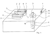
- a turntable 2 On a parallel to the X-axis of the coordinate measuring machine axis 18, a turntable 2 is arranged. On this there is a measuring object 3 and can thus be rotated about the axis of rotation 18 and are moved in the X direction by the axis 18 (double arrow). On a parallel to the Y-axis slide 4 two parallel to the Z-axis axes 5, 6 are arranged. On the mechanical axis 5 is a sensor 7 for X-radiation and an image processing sensor 8. On the mechanical axis 6 is additionally a tactile sensor 9. Opposite the X-ray sensor 7, an X-ray source 10 is arranged, which is either movable or fixedly mounted in the Y direction can be.
- the mechanical axes or slide, which run along the X, Y or Z axis of the coordinate measuring machine, are designed so that the sensors installed in or on the coordinate measuring machine respectively entire measuring range on the turntable 2 can cover.
- the integration of computed tomography (CT) into a multisensor coordinate measuring machine opens up completely new possibilities.
- a fast, non-destructive complete measurement with the tomography is combined with high-precision measurements of functional dimensions with tactile or optical sensors.
- the X-ray sensor system (sensor, radiation source) can be positioned in the coordinate measuring machine corresponding to the second sensor system (eg image processing sensor, transmitted or reflected light beam source or tactile sensor, optionally with associated image processing sensor), ie the X-ray sensor system is equivalent to the second sensor system is arranged.
- the x-ray sensor system with at least the tactile sensor system and / or the optical sensor system can be arranged on a common mechanical axis or arranged on a separate mechanical axis which operates in an analogous manner as the mechanical axes for the tactile and / or optical sensors.
- the workpiece 3 is placed on a turntable 2 and X-rayed.
- the sensor 7 z. B. in the form of a surface detector converts the X-ray image into a digital 2D image for further processing.
- the object 3 is rotated 360 ° and recorded X-ray images in several rotational positions.
- a 3D reconstruction of measuring points is performed, which describes the entire workpiece geometry to be measured.
- the field of application of the computer tomograph can be expanded.
- the image processing sensor 8 the fully automatic measurement of complicated, extremely low-contrast workpieces in transmitted and reflected light is possible. Touch probes enable highly accurate measurements of optically inaccessible features.
- the sensor 7 and the X-ray source 10 are adjusted synchronously, ie at a constant distance from one another to the object 3.
- a measuring range adjustment which may optionally be done automatically.
- the object 3 can be adjusted to the sensor 7, so as to allow adaptation to the workpiece size and the accuracy requirements. If the object 3 is moved towards the sensor 7, the result is a lower magnification, whereas a high magnification can be achieved when the object 3 is moved toward the x-ray source 10.
- the sensor can also be adjusted to the object 3.
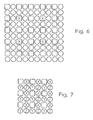
- the squares represent the pixels of a 2D image.
- the existing 2D image is z. B. converted by averaging from adjacent pixels into a lower resolution image with less pixel information (pixels shown as crosses).
- a 3D reconstruction is then carried out to calculate the three-dimensional voxel image.
- the voxel image which is in the Fig. 6 to be taken 2D representation is also simulated by crosses, calculated back into an image of the original resolution by interpolation between multiple voxels, so that - again in 2D representation - again results in a picture with squares.
- a further method according to the invention is to be illustrated by which the resolution in the tomogram can be increased.
- a plurality of images are taken, between which the sensor is moved to the object or the object to the sensor by a distance which is smaller than the edge length of a sensitive element of the sensor.
- the X-ray detector (sensor) used is characterized in its resolution by the pixels drawn as squares.
- a normal can be used, which in the embodiment of the Fig. 8 marked with 50.
- a carrier 54 made of a material which has a low absorption to X-rays.
- the carrier 54 at least two balls 56, 58 of X-ray strongly absorbing material such as steel are arranged.
- the normal 50 is then on a turntable 60, the turntable 2 of the Fig. 1 corresponds to a tomograph arranged.
- the turntable 60 is rotatable about an axis 62 which may coincide with the X-axis of the coordinate measuring machine.
- the Einmessvortician for determining the position of the axis of rotation 62 of the scanner within the coordinate measuring machine are now determined by measuring the positions of the balls 56, 58 relative to the X-ray sensor 7 in different rotational positions of the ball standard 50.
- magnification is to be determined, measurements at two different distances from the sensor 7 are necessary.
- the normal 50 may have two further balls 64, 66.
- Fig. 3 to 5 further inventive features of the teaching of the invention can be seen. It is in Fig. 3 also purely in principle a coordinate measuring machine 110 shown with a housing 112 which comprises a base plate 114, rear wall 116, side walls 118, 120 and a top wall 122, which is also referred to as a cover plate.
- the x-axis, y-axis and z-axis of the coordinate measuring machine are indicated in the drawing by reference numerals 124, 126 and 128.
- a holder 132 for a turntable 134 is adjustable, on which an object to be measured 136 is arranged.
- the turntable 134 is disposed on the x-axis 124.
- the x-axis can be arranged with the measurement object on the turntable.
- a receptacle 138 is displaceable. From the receptacle 138, a holder 140 slidably extends along the z-axis 128.
- an X-ray source 142 whose X-ray radiation passes through the object 136 arranged on the turntable 134, emanates from the baseplate 114.
- the X-radiation is itself detected by suitable sensors such as CCD sensors, which are sensitive to X-radiation.
- sensors 144 may be sensors that are common for coordinate measuring machines, ie z. B. tactile or optical sensors. Thus, both can be tomographed and measured tactilely or optically as with image processing sensors, laser distance sensors, etc.
- the invention provides that at least some of the supporting components exert shielding function. So z. B. the base plate 114 and / or the rear wall 116 may be dimensioned or formed such that the required shielding function is ensured.
- the corresponding walls 114, 116 exert the function required for the metrological structure, namely guidance in the exemplary embodiment for the x and y axes.
- hard rock such as granite or corresponding materials should be used.
- an artificial hard rock such as polymer concrete is conceivable that can be added to the extent necessary with X-ray absorbing material such as magnetic iron or the like.
- the housing 112 of the coordinate measuring machine 110 or parts thereof performs a dual function, namely that of the required shielding and that of functional components of the metrological structure. This results in a compact design.
- Fig. 4 In order to achieve a high measuring density or to have to accept only small irradiation times in the respective measuring position, without any losses being made with respect to the measuring accuracy, according to the representation of the Fig. 4 provided that simultaneously - ie in each measurement position of the object 136 - several tomograms is recorded at different transmission angles. So goes in Fig. 4 according to the statements according to Fig. 3 from the base plate 114 of the turntable 134, on which an unillustrated object to be measured is arranged, which is irradiated by originating from an X-ray source 148 X-ray radiation 150.
- the radiation is detected in the exemplary embodiment of a total of three X-ray sensors 152, 154, 156, so that there are three tomograms for different radiographic directions in a measuring position of the object.
- the sensors 152, 154, 156 are read out and obtained projection images for the tomogram.
- the angular position of the sensors 152, 154, 156 is designed such that the angles between the sensors 152, 154, 156 each differ by integer multiples of the angular step of the turntable 136 used in operating the computer tomograph, the second and the third Sensor 154, 156 to the previous first sensor 152 and second sensor 154 are arranged rotated by one third of the angular step.
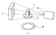
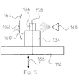
- Fig. 5 In order to record a plurality of tomograms of the object to be measured 136, wherein the angle between the rotation axis 158 of the turntable 154 and the X-radiation 150 is apparently changed, in the exemplary embodiment Fig. 5
- three sensors 160, 162, 164 are arranged at different angles to the main radiation direction of the X-ray source 148, which simulates the apparent pivoting of the X-radiation source to the axis of rotation 158.
- Fig. 5 drawn double arrow 166 is intended to symbolize that the turntable 134 along the axis of rotation 158 parallel to the X-axis is adjustable.
- a calibration body can preferably be tomographed in the form of spheres 300, 302 during tomography, whereby the relative position of the axis of rotation 158 of the turntable 134, on which the object to be measured 136 is arranged.
- the balls 300, 302 can be arranged in a receptacle 304, which shows a low absorption to X-rays, whereas the balls 300, 302 are highly absorbent and z. B. made of steel.
- the position of the rotation axis 158 can be easily determined for the coordinate measuring machine or for the x-ray source 10 or for the sensor 7 and then mathematically corrected.
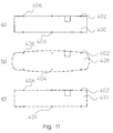
- measuring points are recorded on the measurement object by means of tactile and / or optical sensors and used to correct the measurement points determined with the X-ray sensor system.
- Fig. 11 a measurement object 400, which is measured tactilely and / or optically at selected points.
- Corresponding measuring points are identified by way of example with the reference numbers 402, 404, 406.
- tomography which then takes place in the same coordinate measuring machine, one obtains the shape altered by typical errors in tomography in the tomographed point cloud 408.
- B. tomography typical artifacts.
- the tomographed measuring points are determined on the basis of the measuring points which are more accurately measured with optical and / or tactile sensors and which are in Fig. 11b Once again marked, corrected in their position. In this case, an interpolation may have occurred between the tactile and optically measured measuring points. As a result, one then obtains a geometrically corrected tomographically measured point cloud 410, which corresponds better to the shape of the measurement object 400 than the original data of the tomogram. This shows a comparison of Fig. 11b and 11c ,
- the image processing sensor system for measuring with visible light can be coupled with the same image processing evaluation unit or the same image processing board as the X-ray sensor system, using the transmitted light method.
- Software controlled can then be switched between the two sensors and digitized and calculated in the same hardware.
- Fig. 10 illustrates in the image processing sensors 500 and an X-ray sensor system 502 are connected to the same image processing board 504 in order to be able to work in the manner described above.
Landscapes
- Health & Medical Sciences (AREA)
- Life Sciences & Earth Sciences (AREA)
- Physics & Mathematics (AREA)
- Engineering & Computer Science (AREA)
- Medical Informatics (AREA)
- General Physics & Mathematics (AREA)
- High Energy & Nuclear Physics (AREA)
- Molecular Biology (AREA)
- General Health & Medical Sciences (AREA)
- Nuclear Medicine, Radiotherapy & Molecular Imaging (AREA)
- Radiology & Medical Imaging (AREA)
- Pathology (AREA)
- Biomedical Technology (AREA)
- Heart & Thoracic Surgery (AREA)
- Veterinary Medicine (AREA)
- Public Health (AREA)
- Animal Behavior & Ethology (AREA)
- Biophysics (AREA)
- Surgery (AREA)
- Optics & Photonics (AREA)
- Electromagnetism (AREA)
- Spectroscopy & Molecular Physics (AREA)
- Analytical Chemistry (AREA)
- Pulmonology (AREA)
- Theoretical Computer Science (AREA)
- Immunology (AREA)
- Chemical & Material Sciences (AREA)
- Biochemistry (AREA)
- Analysing Materials By The Use Of Radiation (AREA)
- Length-Measuring Devices Using Wave Or Particle Radiation (AREA)
- Length Measuring Devices With Unspecified Measuring Means (AREA)
Applications Claiming Priority (4)
| Application Number | Priority Date | Filing Date | Title |
|---|---|---|---|
| DE102004026357.4A DE102004026357B4 (de) | 2004-05-26 | 2004-05-26 | Vorrichtung und Verfahren zum Messen eines Objektes |
| DE200410050257 DE102004050257A1 (de) | 2004-10-14 | 2004-10-14 | Anordnung und Verfahren zum Messen von Strukturen von Objekten |
| DE200510018447 DE102005018447A1 (de) | 2005-04-20 | 2005-04-20 | Verfahren zum Messen eines Objektes |
| EP05750966.3A EP1749190B1 (fr) | 2004-05-26 | 2005-05-24 | Procédé de mesure d'un objet utilisant un appareil de mesure de coordonnées incluant un tomodensitomètre |
Related Parent Applications (2)
| Application Number | Title | Priority Date | Filing Date |
|---|---|---|---|
| EP05750966.3A Division-Into EP1749190B1 (fr) | 2004-05-26 | 2005-05-24 | Procédé de mesure d'un objet utilisant un appareil de mesure de coordonnées incluant un tomodensitomètre |
| EP05750966.3 Division | 2005-05-24 |
Publications (2)
| Publication Number | Publication Date |
|---|---|
| EP2192380A2 true EP2192380A2 (fr) | 2010-06-02 |
| EP2192380A3 EP2192380A3 (fr) | 2010-06-23 |
Family
ID=34970088
Family Applications (3)
| Application Number | Title | Priority Date | Filing Date |
|---|---|---|---|
| EP20100002412 Withdrawn EP2192380A3 (fr) | 2004-05-26 | 2005-05-24 | Procédé de mesure d'un objet utilisant une machine de mesure de coordonnées et machine de mesure de coordonnées |
| EP20100184423 Withdrawn EP2282165A3 (fr) | 2004-05-26 | 2005-05-24 | Appareil de mesure de coordonnées et procédé de mesure d'un objet |
| EP05750966.3A Expired - Lifetime EP1749190B1 (fr) | 2004-05-26 | 2005-05-24 | Procédé de mesure d'un objet utilisant un appareil de mesure de coordonnées incluant un tomodensitomètre |
Family Applications After (2)
| Application Number | Title | Priority Date | Filing Date |
|---|---|---|---|
| EP20100184423 Withdrawn EP2282165A3 (fr) | 2004-05-26 | 2005-05-24 | Appareil de mesure de coordonnées et procédé de mesure d'un objet |
| EP05750966.3A Expired - Lifetime EP1749190B1 (fr) | 2004-05-26 | 2005-05-24 | Procédé de mesure d'un objet utilisant un appareil de mesure de coordonnées incluant un tomodensitomètre |
Country Status (4)
| Country | Link |
|---|---|
| US (2) | US8804905B2 (fr) |
| EP (3) | EP2192380A3 (fr) |
| JP (2) | JP5408873B2 (fr) |
| WO (1) | WO2005119174A1 (fr) |
Cited By (2)
| Publication number | Priority date | Publication date | Assignee | Title |
|---|---|---|---|---|
| DE102012113109A1 (de) | 2012-05-07 | 2013-11-07 | Werth Messtechnik Gmbh | Computertomograf |
| DE102014225111B4 (de) * | 2014-12-08 | 2021-04-15 | Siemens Healthcare Gmbh | Verfahren zum Vorbereiten eines Behandlungsraumes füreine Strahlentherapie |
Families Citing this family (77)
| Publication number | Priority date | Publication date | Assignee | Title |
|---|---|---|---|---|
| DE102004003941A1 (de) * | 2004-01-26 | 2005-08-11 | Carl Zeiss Industrielle Messtechnik Gmbh | Bestimmung von Koordinaten eines Werkstücks |
| US8804905B2 (en) * | 2004-05-26 | 2014-08-12 | Werth Messtechnik Gmbh | Coordinate measuring apparatus and method for measuring an object |
| DE102006022104B4 (de) * | 2006-05-11 | 2012-09-06 | Fraunhofer-Gesellschaft zur Förderung der angewandten Forschung e.V. | Vorrichtung zur dreidimensionalen Vermessung eines Festkörpers |
| DE102006022103B4 (de) * | 2006-05-11 | 2013-05-29 | Werth Messtechnik Gmbh | Verfahren zum Vermessen eines Festkörpers |
| DE102007021809A1 (de) * | 2007-04-20 | 2008-10-23 | Werth Messtechnik Gmbh | Verfahren und Vorrichtung zum dimensionellen Messen mit Koordinatenmessgeräten |
| US8224121B2 (en) * | 2007-06-15 | 2012-07-17 | The Boeing Company | System and method for assembling substantially distortion-free images |
| US20090213984A1 (en) * | 2008-02-26 | 2009-08-27 | United Technologies Corp. | Computed Tomography Systems and Related Methods Involving Post-Target Collimation |
| US7639777B2 (en) * | 2008-02-26 | 2009-12-29 | United Technologies Corp. | Computed tomography systems and related methods involving forward collimation |
| US20090225954A1 (en) * | 2008-03-06 | 2009-09-10 | United Technologies Corp. | X-Ray Collimators, and Related Systems and Methods Involving Such Collimators |
| US8238521B2 (en) * | 2008-03-06 | 2012-08-07 | United Technologies Corp. | X-ray collimators, and related systems and methods involving such collimators |
| US7876875B2 (en) * | 2008-04-09 | 2011-01-25 | United Technologies Corp. | Computed tomography systems and related methods involving multi-target inspection |
| US20090274264A1 (en) * | 2008-04-30 | 2009-11-05 | United Technologies Corp. | Computed Tomography Systems and Related Methods Involving Localized Bias |
| US7888647B2 (en) * | 2008-04-30 | 2011-02-15 | United Technologies Corp. | X-ray detector assemblies and related computed tomography systems |
| DE102009043823A1 (de) | 2008-08-28 | 2010-07-29 | Werth Messtechnik Gmbh | Verfahren und Anordnung zum Bestimmen von Strukturen oder Geometrien eines Messobjektes |
| US7775715B2 (en) * | 2008-08-28 | 2010-08-17 | United Technologies Corporation | Method of calibration for computed tomography scanners utilized in quality control applications |
| US8179132B2 (en) * | 2009-02-18 | 2012-05-15 | General Electric Company | Method and system for integrating eddy current inspection with a coordinate measuring device |
| WO2010094774A2 (fr) | 2009-02-20 | 2010-08-26 | Werth Messtechnik Gmbh | Procédé de mesure d'un objet |
| DE202009019014U1 (de) * | 2009-04-30 | 2015-08-31 | Wenzel Volumetrik Gmbh | Computertomographische Werkstückmessvorrichtung |
| US8020308B2 (en) * | 2009-05-29 | 2011-09-20 | General Electric Company | Non-destructive inspection system having self-aligning probe assembly |
| US8655033B2 (en) * | 2009-10-28 | 2014-02-18 | General Electric Company | Iterative reconstruction |
| NL2003840C2 (nl) * | 2009-11-20 | 2011-05-23 | Dirk Peter Leenheer | Werkwijze voor het maken van een numeriek drie-dimensionaal model van een structuur uit zachte en harde delen, drie-dimensionaal model en drager. |
| NL2005040C2 (nl) * | 2009-11-20 | 2011-05-24 | Dirk Peter Leenheer | Werkwijze voor het maken van een numeriek drie-dimensionaal model van een structuur uit zachte en harde delen, drie-dimensionaal model en drager. |
| WO2011064339A2 (fr) * | 2009-11-26 | 2011-06-03 | Werth Messtechnik Gmbh | Procédé et système de détermination tactile-optique de la géométrie d'un objet à mesurer |
| FR2978566B1 (fr) * | 2011-07-25 | 2016-10-28 | Commissariat Energie Atomique | Systeme d'imagerie pour l'imagerie d'objets a mouvement rapide |
| JP2014527663A (ja) * | 2011-07-29 | 2014-10-16 | ヘキサゴン メトロロジー,インコーポレイテッド | 座標測定系データ整理 |
| DE102011113611B3 (de) * | 2011-09-16 | 2012-10-04 | PTW-Freiburg Physikalisch-Technische Werkstätten Dr. Pychlau GmbH | Wasserphantom und Messsystem |
| FR2981450B1 (fr) * | 2011-10-17 | 2014-06-06 | Eads Europ Aeronautic Defence | Systeme et procede de controle de la qualite d'un objet |
| JP2014009976A (ja) * | 2012-06-28 | 2014-01-20 | Hitachi Ltd | 3次元形状計測用x線ct装置およびx線ct装置による3次元形状計測方法 |
| CN104661704B (zh) * | 2012-07-18 | 2017-04-12 | 普林斯顿大学托管委员会 | 多量级光谱纳米显微镜 |
| KR20140087246A (ko) * | 2012-12-28 | 2014-07-09 | 삼성전자주식회사 | 엑스선 영상 장치 및 그 제어 방법 |
| DE102013104490A1 (de) * | 2013-01-25 | 2014-07-31 | Werth Messtechnik Gmbh | Verfahren und Vorrichtung zur Bestimmung der Geometrie von Strukturen mittels Computertomografie |
| US9410905B2 (en) * | 2013-03-27 | 2016-08-09 | United Technologies Corporation | Non-destructive inspection of an article using cross-sections through internal feature |
| US10247682B2 (en) * | 2013-04-04 | 2019-04-02 | Illinois Tool Works Inc. | Helical computed tomography |
| JP6147852B2 (ja) * | 2013-05-10 | 2017-06-14 | 株式会社ニコン | X線装置及び構造物の製造方法 |
| EP3004796B1 (fr) | 2013-05-27 | 2017-03-22 | Carl Zeiss Industrielle Messtechnik GmbH | Dispositif et procédé d'étalonnage d'un appareil de mesure de coordonnées |
| JP6266937B2 (ja) | 2013-09-30 | 2018-01-24 | 株式会社トプコン | 回転レーザ出射装置およびレーザ測量システム |
| DE102014113977A1 (de) | 2013-10-22 | 2015-04-23 | Werth Messtechnik Gmbh | Verfahren zur Bestimmung zumindest eines Parameters bei der dimensionellen Messung mit einer Computertomografiesensorik |
| JP6210841B2 (ja) * | 2013-10-29 | 2017-10-11 | 地方独立行政法人東京都立産業技術研究センター | X線三次元測定装置及びx線三次元測定方法 |
| DE102014116595A1 (de) | 2013-11-15 | 2015-05-21 | Werth Messtechnik Gmbh | Vorrichtung und Verfahren zum Einsatz mehrerer Detektoren bei der dimensionellen Messung mit einer Computertomografiesensorik |
| DE102015101378A1 (de) | 2014-01-30 | 2015-07-30 | Werth Messtechnik Gmbh | Vorrichtung und Verfahren zur Messung von Charakteristika an bzw. von Werkstücken mit Computertomografie |
| FR3019651B1 (fr) * | 2014-04-08 | 2016-05-06 | Univ Joseph Fourier | Dispositif de mesure pour la correction de deplacements parasites dans un tomographe a rayons x |
| US20150286384A1 (en) * | 2014-04-08 | 2015-10-08 | Quality Vision International, Inc. | Method Of Establishing Multi-Sensor Measuring Machine Routines |
| US9750479B2 (en) * | 2014-06-27 | 2017-09-05 | Hexagon Metrology, Inc. | Three-dimensional x-ray CT calibration and verification apparatus and method |
| WO2016021030A1 (fr) | 2014-08-07 | 2016-02-11 | 株式会社ニコン | Appareil à rayons x et procédé de production de structure |
| WO2016055167A1 (fr) | 2014-10-10 | 2016-04-14 | Werth Messtechnik Gmbh | Procédé et dispositif de tomodensitométrie pour une pièce |
| DE102015121127A1 (de) | 2014-12-19 | 2016-06-23 | Werth Messtechnik Gmbh | Verfahren und Vorrichtung zur Computertomografie eines Werkstücks |
| EP3104118B1 (fr) | 2015-06-12 | 2019-02-27 | Hexagon Technology Center GmbH | Procédé permettant de commander un mécanisme d'entraînement d'une machine automatique comportant une caméra |
| US11112238B2 (en) | 2015-07-07 | 2021-09-07 | Quality Vision International Inc. | Method and apparatus for scanning object |
| WO2017070442A1 (fr) | 2015-10-23 | 2017-04-27 | Hexagon Metrology, Inc. | Jauge de tomodensitométrie tridimensionnelle |
| DE102017100594A1 (de) | 2016-01-14 | 2017-07-20 | Werth Messtechnik Gmbh | CT-Parameter-Automat |
| US10585051B2 (en) | 2016-05-24 | 2020-03-10 | Hexagon Metrology, Inc. | X-ray computed tomography gauge |
| JP6767045B2 (ja) | 2016-11-02 | 2020-10-14 | 株式会社ミツトヨ | 計測用x線ct装置と座標測定機の座標合せ治具 |
| DE102018105709A1 (de) | 2017-03-15 | 2018-09-20 | Werth Messtechnik Gmbh | Verfahren zur computertomografischen Messungen von Werkstücken |
| JP6805918B2 (ja) * | 2017-03-23 | 2020-12-23 | コニカミノルタ株式会社 | 放射線画像処理装置及び放射線画像撮影システム |
| CN113624169B (zh) | 2017-04-21 | 2024-07-23 | 株式会社岛津制作所 | 三维形状测量用x射线ct装置的长度测量误差评价用器具 |
| JP7082492B2 (ja) | 2018-01-19 | 2022-06-08 | 株式会社ミツトヨ | 計測用x線ct装置、及び、その干渉防止方法 |
| JP2019128163A (ja) * | 2018-01-19 | 2019-08-01 | 株式会社ミツトヨ | 計測用x線ct装置、及び、その校正方法 |
| US10354374B1 (en) * | 2018-02-27 | 2019-07-16 | James Edward Prindiville | Method of representing the internal conditions in computed tomography |
| CN109602428B (zh) * | 2018-11-05 | 2022-07-22 | 上海逸动医学科技有限公司 | 一种移动式双平面x光系统的立体动态定位系统 |
| TWI715899B (zh) | 2018-12-20 | 2021-01-11 | 財團法人工業技術研究院 | 量測程式編譯裝置與量測程式編譯方法 |
| US11733181B1 (en) | 2019-06-04 | 2023-08-22 | Saec/Kinetic Vision, Inc. | Imaging environment testing fixture and methods thereof |
| JP7286485B2 (ja) * | 2019-09-06 | 2023-06-05 | 株式会社ミツトヨ | 計測用x線ct装置 |
| JP7257924B2 (ja) * | 2019-09-09 | 2023-04-14 | 株式会社ミツトヨ | X線計測装置の校正方法 |
| JP7257925B2 (ja) * | 2019-09-10 | 2023-04-14 | 株式会社ミツトヨ | X線計測装置の校正方法 |
| WO2021087208A1 (fr) * | 2019-10-31 | 2021-05-06 | Smiths Detection Inc. | Système et procédé d'inspection de cargaison par tomodensitométrie au-dessous du sol |
| JP7257942B2 (ja) * | 2019-11-29 | 2023-04-14 | 日立Astemo株式会社 | 表面検査装置および形状矯正装置、並びに表面検査方法および形状矯正方法 |
| US11719651B2 (en) * | 2020-08-05 | 2023-08-08 | Faro Technologies, Inc. | Part inspection method using computed tomography |
| CN112731864B (zh) * | 2020-12-21 | 2022-01-21 | 北京理工大学 | 一种机床加工误差补偿方法、装置及零件加工机床 |
| US12298260B2 (en) * | 2021-07-08 | 2025-05-13 | Illinois Tool Works Inc. | Customizable axes of rotation for industrial radiography systems |
| CN113310422B (zh) * | 2021-07-29 | 2021-10-22 | 成都信息工程大学 | 一种工件特征间距的测量装置及测量方法 |
| CN114280083B (zh) * | 2021-12-16 | 2023-11-07 | 重庆日联科技有限公司 | 一种基于线阵相机自动cnc编程实现工业x光无损检测大尺寸平整铸件的检测方法 |
| DE102023103165A1 (de) | 2022-02-14 | 2023-08-17 | Werth Messtechnik Gmbh | Verfahren und Vorrichtung zur Computertomografie oder Laminografie |
| US11669959B1 (en) | 2022-04-14 | 2023-06-06 | Honeywell Federal Manufacturing & Technologies, Llc | Automated analysis of lattice structures using computed tomography |
| US11480533B1 (en) | 2022-04-14 | 2022-10-25 | Honeywell Federal Manufacturing & Technologies, Llc | Multi-scan computed tomography defect detectability |
| US20240005048A1 (en) * | 2022-06-29 | 2024-01-04 | Siemens Industry Software Inc. | Bounding box-based visualization of computer-aided design (cad) models via pixel color analyses |
| US20240310306A1 (en) * | 2023-03-13 | 2024-09-19 | The Boeing Company | X-ray line scan for foreign object debris detection |
| CN120635065B (zh) * | 2025-08-11 | 2025-10-14 | 深圳大学 | 一种基于x射线双目成像的混凝土骨料位置追踪系统及方法 |
Family Cites Families (68)
| Publication number | Priority date | Publication date | Assignee | Title |
|---|---|---|---|---|
| US5015A (en) * | 1847-03-13 | Mode of producing reciprocating and latkral motions | ||
| BE519407A (fr) | 1952-06-03 | 1900-01-01 | ||
| CH386133A (de) * | 1961-02-24 | 1964-12-31 | Forschungsanstalt Fuer Strahle | Verfahren und Einrichtung zur Materialprüfung |
| US4422177A (en) * | 1982-06-16 | 1983-12-20 | American Science And Engineering, Inc. | CT Slice proximity rotary table and elevator for examining large objects |
| JPS6064235A (ja) * | 1983-09-20 | 1985-04-12 | Toshiba Corp | Ctスキヤナ |
| JPS60181641A (ja) * | 1984-02-29 | 1985-09-17 | Toshiba Ceramics Co Ltd | 産業用x線断層撮影装置 |
| US5038378A (en) | 1985-04-26 | 1991-08-06 | Schlumberger Technology Corporation | Method and apparatus for smoothing measurements and detecting boundaries of features |
| DE3806686A1 (de) | 1988-03-02 | 1989-09-14 | Wegu Messtechnik | Mehrkoordinatenmess- und -pruefeinrichtung |
| NL8800614A (nl) | 1988-03-14 | 1989-10-02 | Philips Nv | Roentgenonderzoek apparaat met drie rotatie assen. |
| IT1217701B (it) * | 1988-05-24 | 1990-03-30 | Gen Medical Merate Spa | Procedimento di calibrazione numerica di installazione di radiologia e installazione di calibrazione numerica per la messa in opera del procedimento |
| JPH0692885B2 (ja) * | 1990-01-10 | 1994-11-16 | 新日本製鐵株式会社 | X線ct装置 |
| JP3112025B2 (ja) * | 1990-10-26 | 2000-11-27 | 株式会社日立製作所 | 生体計測装置 |
| JP2729542B2 (ja) | 1991-02-22 | 1998-03-18 | 富士写真フイルム株式会社 | ハロゲン化銀カラー写真感光材料用の処理液及びそれを用いた処理方法 |
| DE9103229U1 (de) | 1991-03-16 | 1992-07-16 | Mauser-Werke Oberndorf Gmbh, 78727 Oberndorf | Meß- und Verarbeitungsstation für große Werkstücke |
| FR2700909B1 (fr) * | 1993-01-27 | 1995-03-17 | Gen Electric Cgr | Dispositif et procédé automatique de calibration géométrique d'un système d'imagerie par rayons X. |
| JP2904248B2 (ja) * | 1993-03-01 | 1999-06-14 | 株式会社東京精密 | 座標測定機用ロータリテーブルの校正方法 |
| JP3449561B2 (ja) * | 1993-04-19 | 2003-09-22 | 東芝医用システムエンジニアリング株式会社 | X線ct装置 |
| DE4415947C2 (de) | 1994-03-25 | 1999-04-22 | Thermoselect Ag | Verfahren zur Aufbereitung und Verwertung metallhaltiger Abscheidungen aus der Gasreinigung bei der thermischen Abfallbehandlung |
| FR2721497B1 (fr) * | 1994-06-22 | 1996-12-06 | Ge Medical Syst Sa | Dispositif lumineux de localisation et de pointage tridimensionel pour applications médicales. |
| DE4445331C5 (de) | 1994-12-19 | 2006-07-27 | Mycrona Gesellschaft für innovative Messtechnik mbH | Automatischer Multisensormeßkopf für Koordinatenmeßgeräte |
| US5615244A (en) * | 1995-05-25 | 1997-03-25 | Morton International, Inc. | Real time radiographic inspection system |
| AU7730696A (en) * | 1995-11-13 | 1997-06-05 | United States Of America, As Represented By The Secretary Of The Army, The | Apparatus and method for automatic recognition of concealed objects using multiple energy computed tomography |
| US5912938A (en) * | 1996-10-07 | 1999-06-15 | Analogic Corporation | Tomography system having detectors optimized for parallel beam image reconstruction |
| US5764721A (en) * | 1997-01-08 | 1998-06-09 | Southwest Research Institute | Method for obtaining optimized computed tomography images from a body of high length-to-width ratio using computer aided design information for the body |
| US5848115A (en) * | 1997-05-02 | 1998-12-08 | General Electric Company | Computed tomography metrology |
| US5963612A (en) * | 1997-12-31 | 1999-10-05 | Siemens Corporation Research, Inc. | Apparatus for C-arm calibration for 3D reconstruction in an imaging system utilizing planar transformation |
| US6289235B1 (en) * | 1998-03-05 | 2001-09-11 | Wake Forest University | Method and system for creating three-dimensional images using tomosynthetic computed tomography |
| DE29808320U1 (de) * | 1998-05-12 | 1998-10-15 | Wegu-Messtechnik GmbH, 66787 Wadgassen | Mehrkoordinatenmeß- und -prüfeinrichtung |
| JP2000121580A (ja) * | 1998-08-11 | 2000-04-28 | Hitachi Ltd | X線缶巻締部測定装置及び測定開始点検出方法 |
| JP2000140137A (ja) * | 1998-08-31 | 2000-05-23 | Sumitomo Heavy Ind Ltd | 放射線治療の患者位置決め方法及び装置 |
| US6148058A (en) * | 1998-10-23 | 2000-11-14 | Analogic Corporation | System and method for real time measurement of detector offset in rotating-patient CT scanner |
| JP2001041728A (ja) * | 1999-07-30 | 2001-02-16 | Canon Inc | 断面寸法測定方法および装置 |
| DE10001239A1 (de) | 2000-01-14 | 2001-07-26 | Leica Microsystems | Messgerät und Verfahren zum Vermessen von Strukturen auf einem Substrat |
| US6947038B1 (en) * | 2000-04-27 | 2005-09-20 | Align Technology, Inc. | Systems and methods for generating an appliance with tie points |
| DE10021219A1 (de) * | 2000-04-29 | 2001-10-31 | Philips Corp Intellectual Pty | Computertomographie-Verfahren |
| JP4374753B2 (ja) * | 2000-08-11 | 2009-12-02 | 株式会社島津製作所 | X線ct装置 |
| JP3427046B2 (ja) * | 2000-08-29 | 2003-07-14 | 株式会社日立製作所 | 3次元寸法計測装置及びその計測方法 |
| DE10044169A1 (de) * | 2000-09-07 | 2002-03-21 | Daimler Chrysler Ag | Verfahren zur zerstörungsfreien Wandstärkenprüfung |
| FI109653B (fi) * | 2000-10-11 | 2002-09-30 | Instrumentarium Corp | Menetelmä ja laitteisto potilaan pään alueen kuvaamiseksi |
| DE10051370A1 (de) * | 2000-10-17 | 2002-05-02 | Brainlab Ag | Verfahren und Vorrichtung zur exakten Patientenpositionierung in der Strahlentherapie und Radiochirurgie |
| US6470068B2 (en) * | 2001-01-19 | 2002-10-22 | Cheng Chin-An | X-ray computer tomography scanning system |
| FR2822273B1 (fr) * | 2001-03-13 | 2003-07-11 | Ge Med Sys Global Tech Co Llc | Procede d'etalonnage pour la reconstruction de modelisations tri-dimensionnelles a partir d'images obtenues par tomographie |
| DK174493B1 (da) | 2001-05-22 | 2003-04-22 | Maersk Olie & Gas | Fremgangsmåde til styring af injektionsfrakturers udbredelsesretning i permeable formationer |
| US6611575B1 (en) * | 2001-07-27 | 2003-08-26 | General Electric Company | Method and system for high resolution 3D visualization of mammography images |
| DE10140867B4 (de) * | 2001-08-21 | 2005-08-18 | Siemens Ag | Kalibrierphantom für projektive Röntgensysteme |
| US6636581B2 (en) | 2001-08-31 | 2003-10-21 | Michael R. Sorenson | Inspection system and method |
| DE10156445A1 (de) * | 2001-11-16 | 2003-05-28 | Philips Corp Intellectual Pty | Verfahren und Vorrichtung zur Kalibrierung von und zur Bilderzeugung mit einer schwerkraftempfindlichen Bildaufnahmeeinrichtung |
| US6751285B2 (en) * | 2001-11-21 | 2004-06-15 | General Electric Company | Dose management system for mammographic tomosynthesis |
| FR2834197B1 (fr) * | 2001-12-28 | 2004-02-27 | Optimage | Procede et dispositif d'evaluation des forces d'equilibrage du squelette |
| JP3431022B1 (ja) * | 2002-02-15 | 2003-07-28 | 株式会社日立製作所 | 3次元寸法計測装置及び3次元寸法計測方法 |
| US7269243B2 (en) * | 2002-02-25 | 2007-09-11 | Ge Medical Systems Global Technology Company, Llc | Method and apparatus for controlling electron beam motion based on calibration information |
| JP4172201B2 (ja) * | 2002-04-30 | 2008-10-29 | コニカミノルタホールディングス株式会社 | 放射線撮影装置及び放射線画像形成装置 |
| JP2004012407A (ja) * | 2002-06-11 | 2004-01-15 | Hitachi Ltd | 透過画像提供システムおよびx線ct・dr撮影サービスシステム |
| CA2391133C (fr) * | 2002-06-21 | 2011-02-15 | Jiwei Yang | Methode et appareil servant a mesurer l'epaisseur d'objets comprimes |
| EP1380263B1 (fr) * | 2002-07-12 | 2007-08-29 | MYCRONA Gesellschaft für innovative Messtechnik mbH | Procédé et dispositif pour la mesure de la position instantanée d'une structure d'un objet à examiner |
| US7356115B2 (en) * | 2002-12-04 | 2008-04-08 | Varian Medical Systems Technology, Inc. | Radiation scanning units including a movable platform |
| US7198404B2 (en) * | 2003-04-03 | 2007-04-03 | Siemens Medical Solutions Usa, Inc. | Real-time acquisition of co-registered X-ray and optical images |
| US7186023B2 (en) * | 2003-06-10 | 2007-03-06 | Shimadzu Corporation | Slice image and/or dimensional image creating method |
| US7170966B2 (en) * | 2003-08-05 | 2007-01-30 | Gioietta Kuo-Petravic | Practical implementation of a CT cone beam algorithm for 3-D image reconstruction as applied to nondestructive inspection of baggage, live laboratory animal and any solid materials |
| WO2005015125A1 (fr) * | 2003-08-08 | 2005-02-17 | University Health Network | Procede et systeme pour etalonner un instrument source et detecteur |
| US7016456B2 (en) * | 2003-10-31 | 2006-03-21 | General Electric Company | Method and apparatus for calibrating volumetric computed tomography systems |
| US7693325B2 (en) * | 2004-01-14 | 2010-04-06 | Hexagon Metrology, Inc. | Transprojection of geometry data |
| US8804905B2 (en) * | 2004-05-26 | 2014-08-12 | Werth Messtechnik Gmbh | Coordinate measuring apparatus and method for measuring an object |
| US7003070B1 (en) * | 2004-08-03 | 2006-02-21 | William Barry Chen | Upright CT scanner |
| US7344307B2 (en) * | 2004-11-12 | 2008-03-18 | General Electric Company | System and method for integration of a calibration target into a C-arm |
| US20060239398A1 (en) * | 2005-03-07 | 2006-10-26 | Fused Multimodality Imaging, Ltd. | Breast diagnostic apparatus for fused SPECT, PET, x-ray CT, and optical surface imaging of breast cancer |
| US8777485B2 (en) * | 2010-09-24 | 2014-07-15 | Varian Medical Systems, Inc. | Method and apparatus pertaining to computed tomography scanning using a calibration phantom |
| US8764290B2 (en) * | 2012-01-30 | 2014-07-01 | Hexagon Metrology, Inc. | X-ray computed tomography device calibration and verification apparatus |
-
2005
- 2005-05-24 US US11/597,625 patent/US8804905B2/en not_active Expired - Fee Related
- 2005-05-24 EP EP20100002412 patent/EP2192380A3/fr not_active Withdrawn
- 2005-05-24 WO PCT/EP2005/005598 patent/WO2005119174A1/fr not_active Ceased
- 2005-05-24 JP JP2007513786A patent/JP5408873B2/ja not_active Expired - Fee Related
- 2005-05-24 EP EP20100184423 patent/EP2282165A3/fr not_active Withdrawn
- 2005-05-24 EP EP05750966.3A patent/EP1749190B1/fr not_active Expired - Lifetime
-
2012
- 2012-08-03 JP JP2012172753A patent/JP2012233919A/ja active Pending
-
2014
- 2014-07-03 US US14/323,522 patent/US9625257B2/en not_active Expired - Fee Related
Non-Patent Citations (1)
| Title |
|---|
| None |
Cited By (2)
| Publication number | Priority date | Publication date | Assignee | Title |
|---|---|---|---|---|
| DE102012113109A1 (de) | 2012-05-07 | 2013-11-07 | Werth Messtechnik Gmbh | Computertomograf |
| DE102014225111B4 (de) * | 2014-12-08 | 2021-04-15 | Siemens Healthcare Gmbh | Verfahren zum Vorbereiten eines Behandlungsraumes füreine Strahlentherapie |
Also Published As
| Publication number | Publication date |
|---|---|
| WO2005119174A1 (fr) | 2005-12-15 |
| US9625257B2 (en) | 2017-04-18 |
| US8804905B2 (en) | 2014-08-12 |
| US20080075227A1 (en) | 2008-03-27 |
| JP2008500521A (ja) | 2008-01-10 |
| JP5408873B2 (ja) | 2014-02-05 |
| JP2012233919A (ja) | 2012-11-29 |
| EP1749190B1 (fr) | 2015-05-06 |
| EP2282165A2 (fr) | 2011-02-09 |
| EP1749190A1 (fr) | 2007-02-07 |
| EP2192380A3 (fr) | 2010-06-23 |
| EP2282165A3 (fr) | 2011-02-16 |
| US20150030121A1 (en) | 2015-01-29 |
Similar Documents
| Publication | Publication Date | Title |
|---|---|---|
| EP1749190B1 (fr) | Procédé de mesure d'un objet utilisant un appareil de mesure de coordonnées incluant un tomodensitomètre | |
| EP2399237B1 (fr) | Procédé de mesure d'un objet | |
| EP1380263B1 (fr) | Procédé et dispositif pour la mesure de la position instantanée d'une structure d'un objet à examiner | |
| EP1760457B1 (fr) | Procédé et dispositif destinés au calibrage d'un système de mesure | |
| DE102004026357B4 (de) | Vorrichtung und Verfahren zum Messen eines Objektes | |
| EP2268204B1 (fr) | Dispositif et procédé mis en oeuvre par ordinateur pour réaliser une tomodensitométrie sans rotation | |
| DE102018105709A1 (de) | Verfahren zur computertomografischen Messungen von Werkstücken | |
| EP2140254A2 (fr) | Procédé et dispositif de mesure dimensionnelle au moyen d'appareils de mesure de coordonnées | |
| DE102017100594A1 (de) | CT-Parameter-Automat | |
| WO2008119555A1 (fr) | Procédé et système de mesure pour produire des images tridimensionnelles d'objets mesurés par rayonnement à caractère invasif | |
| DE102013108367A1 (de) | Vorrichtung und Verfahren zur Aufnahme von Durchstrahlungsbildern bei einer Computertomografie | |
| WO2022268760A1 (fr) | Système de tomographie assistée par ordinateur et procédé pour faire fonctionner un système de tomographie assistée par ordinateur | |
| WO2007131724A1 (fr) | Système de mesure tridimensionnelle d'un corps solide | |
| EP0326840B1 (fr) | Procédé et appareil pour la production d'image radiographique | |
| EP2644095A1 (fr) | Système de tomodensitométrie et procédé de détermination de dates pour un enregistrement tomodensitométrique à perturbation corrigée d'un objet d'étude | |
| DE102014116595A1 (de) | Vorrichtung und Verfahren zum Einsatz mehrerer Detektoren bei der dimensionellen Messung mit einer Computertomografiesensorik | |
| DE102022103888A1 (de) | Verfahren und Vorrichtung zur Computertomografiemessung | |
| DE102006022103B4 (de) | Verfahren zum Vermessen eines Festkörpers | |
| DE102021204628B3 (de) | Verfahren zum Betreiben eines Computertomographen beim Vermessen einer Interessensregion eines Objekts und Computertomograph | |
| DE102005018447A1 (de) | Verfahren zum Messen eines Objektes | |
| DE102004050257A1 (de) | Anordnung und Verfahren zum Messen von Strukturen von Objekten |
Legal Events
| Date | Code | Title | Description |
|---|---|---|---|
| PUAI | Public reference made under article 153(3) epc to a published international application that has entered the european phase |
Free format text: ORIGINAL CODE: 0009012 |
|
| PUAL | Search report despatched |
Free format text: ORIGINAL CODE: 0009013 |
|
| AC | Divisional application: reference to earlier application |
Ref document number: 1749190 Country of ref document: EP Kind code of ref document: P |
|
| AK | Designated contracting states |
Kind code of ref document: A2 Designated state(s): AT BE BG CH CY CZ DE DK EE ES FI FR GB GR HU IE IS IT LI LT LU MC NL PL PT RO SE SI SK TR |
|
| AK | Designated contracting states |
Kind code of ref document: A3 Designated state(s): AT BE BG CH CY CZ DE DK EE ES FI FR GB GR HU IE IS IT LI LT LU MC NL PL PT RO SE SI SK TR |
|
| 17P | Request for examination filed |
Effective date: 20101216 |
|
| 17Q | First examination report despatched |
Effective date: 20110303 |
|
| APBK | Appeal reference recorded |
Free format text: ORIGINAL CODE: EPIDOSNREFNE |
|
| APBN | Date of receipt of notice of appeal recorded |
Free format text: ORIGINAL CODE: EPIDOSNNOA2E |
|
| APBR | Date of receipt of statement of grounds of appeal recorded |
Free format text: ORIGINAL CODE: EPIDOSNNOA3E |
|
| APAF | Appeal reference modified |
Free format text: ORIGINAL CODE: EPIDOSCREFNE |
|
| APBT | Appeal procedure closed |
Free format text: ORIGINAL CODE: EPIDOSNNOA9E |
|
| STAA | Information on the status of an ep patent application or granted ep patent |
Free format text: STATUS: THE APPLICATION HAS BEEN WITHDRAWN |
|
| 18W | Application withdrawn |
Effective date: 20191022 |