EP2192390A2 - Débitmètre à induction magnétique - Google Patents
Débitmètre à induction magnétique Download PDFInfo
- Publication number
- EP2192390A2 EP2192390A2 EP09014554A EP09014554A EP2192390A2 EP 2192390 A2 EP2192390 A2 EP 2192390A2 EP 09014554 A EP09014554 A EP 09014554A EP 09014554 A EP09014554 A EP 09014554A EP 2192390 A2 EP2192390 A2 EP 2192390A2
- Authority
- EP
- European Patent Office
- Prior art keywords
- measuring
- measuring electrodes
- magnetic
- cover layer
- electrodes
- Prior art date
- Legal status (The legal status is an assumption and is not a legal conclusion. Google has not performed a legal analysis and makes no representation as to the accuracy of the status listed.)
- Granted
Links
Images

Classifications
-
- G—PHYSICS
- G01—MEASURING; TESTING
- G01F—MEASURING VOLUME, VOLUME FLOW, MASS FLOW OR LIQUID LEVEL; METERING BY VOLUME
- G01F1/00—Measuring the volume flow or mass flow of fluid or fluent solid material wherein the fluid passes through a meter in a continuous flow
- G01F1/56—Measuring the volume flow or mass flow of fluid or fluent solid material wherein the fluid passes through a meter in a continuous flow by using electric or magnetic effects
- G01F1/58—Measuring the volume flow or mass flow of fluid or fluent solid material wherein the fluid passes through a meter in a continuous flow by using electric or magnetic effects by electromagnetic flowmeters
- G01F1/584—Measuring the volume flow or mass flow of fluid or fluent solid material wherein the fluid passes through a meter in a continuous flow by using electric or magnetic effects by electromagnetic flowmeters constructions of electrodes, accessories therefor
-
- G—PHYSICS
- G01—MEASURING; TESTING
- G01F—MEASURING VOLUME, VOLUME FLOW, MASS FLOW OR LIQUID LEVEL; METERING BY VOLUME
- G01F1/00—Measuring the volume flow or mass flow of fluid or fluent solid material wherein the fluid passes through a meter in a continuous flow
- G01F1/002—Measuring the volume flow or mass flow of fluid or fluent solid material wherein the fluid passes through a meter in a continuous flow wherein the flow is in an open channel
-
- G—PHYSICS
- G01—MEASURING; TESTING
- G01F—MEASURING VOLUME, VOLUME FLOW, MASS FLOW OR LIQUID LEVEL; METERING BY VOLUME
- G01F15/00—Details of, or accessories for, apparatus of groups G01F1/00 - G01F13/00 insofar as such details or appliances are not adapted to particular types of such apparatus
- G01F15/006—Details of, or accessories for, apparatus of groups G01F1/00 - G01F13/00 insofar as such details or appliances are not adapted to particular types of such apparatus characterised by the use of a particular material, e.g. anti-corrosive material
-
- Y—GENERAL TAGGING OF NEW TECHNOLOGICAL DEVELOPMENTS; GENERAL TAGGING OF CROSS-SECTIONAL TECHNOLOGIES SPANNING OVER SEVERAL SECTIONS OF THE IPC; TECHNICAL SUBJECTS COVERED BY FORMER USPC CROSS-REFERENCE ART COLLECTIONS [XRACs] AND DIGESTS
- Y10—TECHNICAL SUBJECTS COVERED BY FORMER USPC
- Y10T—TECHNICAL SUBJECTS COVERED BY FORMER US CLASSIFICATION
- Y10T29/00—Metal working
- Y10T29/49—Method of mechanical manufacture
- Y10T29/49002—Electrical device making
- Y10T29/4902—Electromagnet, transformer or inductor
-
- Y—GENERAL TAGGING OF NEW TECHNOLOGICAL DEVELOPMENTS; GENERAL TAGGING OF CROSS-SECTIONAL TECHNOLOGIES SPANNING OVER SEVERAL SECTIONS OF THE IPC; TECHNICAL SUBJECTS COVERED BY FORMER USPC CROSS-REFERENCE ART COLLECTIONS [XRACs] AND DIGESTS
- Y10—TECHNICAL SUBJECTS COVERED BY FORMER USPC
- Y10T—TECHNICAL SUBJECTS COVERED BY FORMER US CLASSIFICATION
- Y10T29/00—Metal working
- Y10T29/49—Method of mechanical manufacture
- Y10T29/49826—Assembling or joining
Definitions
- the invention relates to a magnetic-inductive flowmeter for measuring the flow of a flowing medium, with a measuring line, with a magnetic field generating means for generating a measuring line at least partially passing magnetic field and with two measuring electrodes for detecting and tapping an induced in the flowing medium measuring voltage, the measuring line inside at least partially provided with an electrically insulating cover layer and wherein the measuring voltage can be tapped galvanically or capacitively at the measuring electrodes.
- the measuring line is electrically conductive, which thus has a metallic measuring line; only then an electrically insulating cover layer is at least partially required. This electrically insulating cover layer is provided at least in the region of the measuring electrodes.
- the cover layer should at least depend on the diameter of the measuring line.
- the cover layer in the longitudinal direction of the measuring line has an extent which corresponds approximately to at least twice the diameter of the measuring line.
- the measuring line can also - partially or completely - be provided with a cover layer, if it is not electrically conductive.
- the housing usually has a circular cross-section.
- Magnetic-inductive flowmeters have been widely known in the art for decades; this is exemplified by the reference “ Technical Flow Measurement "by Prof. Dr.-Ing. KW Bonfig, 3rd edition, Vulkan-Verlag Essen, 2002, pages 123 to 167 , referenced (see also the German Offenlegungsschriften 196 37 761 . 197 52 368 and 10 2007 003 614 as well as the European publications 0 274 768 . 0 762 084 and 1 764 587 ).
- the Faraday's law of induction is exploited in magnetic-inductive flowmeters in that by means of a magnetic field generating device, which usually has two energized magnetic coils, generates a magnetic field and at least partially passed through a measuring line, wherein the generated magnetic field has at least one component perpendicular to the Flow direction runs.
- a magnetic field generating device which usually has two energized magnetic coils, generates a magnetic field and at least partially passed through a measuring line, wherein the generated magnetic field has at least one component perpendicular to the Flow direction runs.
- each volume element of the flowing medium moving through the magnetic field and having a certain number of charge carriers, with the field strength arising in this volume element contributes to a measuring voltage which can be detected by the measuring electrodes and can be tapped galvanically or capacitively.
- the flowing medium may be a gas-free or at least substantially gas-free liquid, but in the flowing medium may also be a liquid containing more or less gas fractions.
- the measuring line can be completely filled in operation or else only partially filled.
- the invention relates to a magnetic-inductive flowmeter for measuring the flow of a flowing medium.
- a magnetic-inductive flowmeter allows not only the flow measurement of a flowing medium, but also a conductivity measurement and / or a level measurement, with the level measurement, a statement can be obtained as to whether the measuring line is completely or only partially filled. Consequently, a magneto-inductive flowmeter of the type described above for flow measurement, conductivity measurement and / or level measurement can be used.
- magnetic flowmeters are not only used for a conductivity measurement and not only for a level measurement.
- a magneto-inductive flowmeter of the type in question usually serves for a flow measurement and a conductivity measurement, for a flow measurement and a fill level measurement or for a flow measurement, a conductivity measurement and a fill level measurement ,
- a magnetic-inductive flowmeter only for a conductivity measurement, only for a level measurement or only for a conductivity measurement and level measurement.
- a magnetic-inductive flowmeter for measuring the flow of a flowing medium. Regardless, what is said below is always applicable to a magnetic flowmeter for flow measurement and conductivity measurement, flow measurement and level measurement, flow measurement, conductivity measurement and level measurement, conductivity measurement, level measurement or conductivity measurement and level measurement ,
- Magnetic-inductive flowmeters in which the measuring line has at least partially an electrically insulating cover layer, are known in many cases (see German Offenlegungsschriften 10 2004 057 696 . 10 2006 026 310 and 10 2006 026 311 , the German patent 43 27 826 and the European patent application 0 608 793 ).
- cover layer which may have a layer thickness in the range of 0.1 to 500 microns, possibly also beyond, plastics are usually used, for.
- polyurethane polyolefin, polytetrafluoroethylene or polyetheretherketone.
- a preferred embodiment of a magneto-inductive flowmeter according to the invention of the type described above is initially and essentially characterized in that the measuring electrodes are designed strip-like, a length - in the circumferential direction of the measuring line - from slightly less than a quarter of the Meß effets contactss to slightly more than half Have the Meß effetselless and direct, ie electrically conductive, so have galvanic contact with the flowing medium.
- Such an embodiment has over the known in the prior art embodiments functional, but in particular constructive and manufacturing advantages.
- the measuring electrodes of the same material or a similar material as the cover layer exist and the material of the measuring electrodes has a much higher electrical conductivity than the material of the cover layer.
- plastics are usually used as material for the cover layer, for.
- polyurethane polyolefin, polytetrafluoroethylene or polyetheretherketone.
- the measuring electrodes are made of the same material or a similar material as the covering layer, this must be understood, of course, as clarifying or restricting, that both with the same material and with the same material, it must also be realized that the material of the measuring electrodes has a considerably higher electrical conductivity than the material of the covering layer.
- the same material can not mean absolutely identical material here.
- the material of the measuring electrodes has a much higher electrical conductivity than the material of the cover layer.
- the necessary higher electrical conductivity of the material of the measuring electrodes relative to the electrical conductivity of the material of the cover layer can be achieved by a special chemical and / or physical treatment and / or by at least one additive.
- the material of the measuring electrodes has a much higher electrical conductivity than the material of the cover layer, of course, and above all depends on it if, if so, to what extent the material used for the measuring electrodes has a higher electrical conductivity than the material of the covering layer even without special chemical and / or physical treatment and without an additive.
- the material of the measuring electrodes must have a much higher electrical conductivity than that of the covering material. But it is also necessary that the electrical conductivity of the material of the measuring electrodes is substantially higher than the electrical conductivity of the flowing medium, preferably by about twice to about ten times. In this case, it must be taken into consideration which electrical conductivity is to be expected in the flowing medium.
- the electrical conductivity is about 500 ⁇ Scm for drinking water and about 5000 ⁇ Scm for wastewater.
- plastics are generally used as the material for the cover layer, eg. As polyurethane, polyolefin, polytetrafluoroethylene or polyetheretherketone. Such materials can also be used in the magnetic inductive flowmeter according to the invention for the cover layer of the measuring line.
- a polymer As a material for the measuring electrodes, in principle, a polymer can be used, for. As polyurethane (PUR), polyamide (PA), polyethylene / polyethene (PE), polypropylene / Polypropeen (PP), a known under the brand Teflon plastic (PFA, PTFE, ETFE) or rubber of various kinds.
- PUR polyurethane
- PA polyamide
- PE polyethylene / polyethene
- PP polypropylene / Polypropeen
- PFA Teflon plastic
- PTFE PTFE
- ETFE Teflon plastic
- the material of the measuring electrodes has a significantly higher electrical conductivity than the material of the cover layer.
- the necessary higher electrical conductivity of the material of the measuring electrodes relative to the electrical conductivity of the material of the covering layer can be achieved by a special chemical and / or physical treatment and / or by at least one additive.
- a particularly preferred embodiment of the magneto-inductive flowmeter according to the invention is characterized in that a polymer with extrinsic conductivity or a material with intrinsic conductivity is used as the material for the measuring electrodes.
- Extrinsic conductivity refers to the proportion of the conductivity of a solid, which is caused by the incorporation of foreign atoms (external influence ⁇ extrinsic) in the crystal lattice (see “Wikipedia, the free encyclopedia”).
- the introduction of foreign atoms is called doping.
- the foreign atoms cause an increase in the conductivity, since - depending on the number of their valence electrodes - additional vacancies or additional freely movable Insert charges into the solid.
- the extrinsic conductivity is almost independent of temperature at low temperatures and also exists at 0 K.
- Intrinsic conductivity arises from the fact that solids (intrinsically ⁇ intrinsically) tend to form lattice defects and thus allow a charge movement, ie an ionic conduction, ie are electrically conductive (see "Wikipedia, the free encyclopedia").
- lattice defects such. B. Schottky defects and Frenkel defects occur. They are thermodynamically favored, as they bring an entropy gain. The system therefore tends to form defects to some extent. These errors are called intrinsic errors.
- the defect concentration is temperature-dependent. It rises with the temperature and has the value zero at 0 K. Consequently, intrinsic defects at temperatures> 0 K cause mobile charges and thus intrinsic electrical conductivity.
- Materials having electrical conductivity may have both extrinsic conductivity and intrinsic conductivity. At low temperatures, extrinsic conductivity dominates, while at higher temperatures it is masked by intrinsic conductivity (see again “Wikipidea, the Free Encyclopedia”).
- the magnetic-inductive flowmeter according to the invention can be used as additive or as additives for the material of the measuring electrodes carbon, z. B. in the form of graphite, also in the form of carbon fibers, metal or other electrical material, each preferably in powder or fibrous form, be used.
- the measuring electrodes - seen on the measuring electrodes in stretched, as it were "unwound" form - have a rectangular shape or a variable over the Meßtechnischsce shape, z. B. a triangular or a rhombic shape.
- the measuring electrodes can have a circular, an elliptical, a square, a rectangular, an octagonal or a partially circular and / or elliptical and / or square and / or rectangular and / or octagonal cross section.
- shape of the measuring electrodes is also to be noted that they may be rounded at their ends or may be in a circular cross section and / or that they may have a venturi-like cross-section in the flow direction of the flowing medium.
- a preferred embodiment of a magneto-inductive flowmeter according to the invention is first and essentially characterized in that the measuring electrodes are strip-like, a length - in the circumferential direction of the measuring line - from a little less than a quarter of the Meß eins contactss to something more as half of the Meß effets houses and direct, d. H. electrically conductive, so have galvanic contact with the flowing medium.
- This strip-like design of the measuring electrodes may be a one-piece design, but the measuring electrodes may also consist of a plurality of partial electrodes.
- the arrangement of the measuring electrodes relative to the cover layer may be such that the surface of the measuring electrodes directed into the interior of the measuring line is flush with the surface of the cover layer directed into the interior of the measuring line, ie the measuring electrodes are, as it were, completely integrated in the cover layer.
- the flowing medium thus finds a consistently smooth, projections or recesses not having flow channel in front.
- Functional necessary for a magnetic-inductive flowmeter of the type in question are exactly two electrodes, perpendicular to the magnetic field and perpendicular to the flow direction of the flowing medium.
- a plurality of measuring electrodes in the flow direction of the flowing medium in the flow direction of the flowing medium in the flow direction of the flowing medium according to the invention in magnetic flowmeters, so that not only two measuring electrodes, but z. B. four measuring electrodes or even six measuring electrodes are provided.
- the arrangement of a plurality of measuring electrodes in the flow direction of the flowing medium one behind the other can also have the advantage that there are at least several measuring system available, with a total of four measuring electrodes so two measuring systems, with a total of six measuring electrodes so three measuring systems. This has the advantage that such a magneto-inductive flowmeter is also functional and remains when the flow measurement via two opposing measuring electrodes, for whatever reason, is faulty or even fails.
- the measuring voltage induced in the flowing medium and detected by the measuring electrodes naturally has to be picked up by the measuring electrodes be spent so from the "place of origin", the interior of the measuring line to the outside, so that the induced and detected measuring voltage can be evaluated.
- connection elements may be provided with a preferably lenticular head resting on the measuring electrodes in the interior of the measuring line.
- Another embodiment of magnetic-inductive flow measuring devices is characterized with respect to the tapping of the measuring voltage induced in the flowing medium and detected by the measuring electrodes, characterized in that the measuring electrodes are provided with the cover layer and the measuring line penetrating, preferably circular cylindrical terminal receptacles; These connection receptacles can preferably be made in one piece with the measuring electrodes. In this embodiment, it is then recommended to carry out the connecting elements bolt-shaped and plug into the terminal receptacles of the measuring electrodes.
- the teaching of the invention includes not only the previously described in various embodiments magnetic-inductive flowmeter, the teaching of the invention but rather include preferred method for producing magnetic-inductive flowmeters, the cover layer, the measuring electrodes, the realization of the cover layer and the measuring electrodes and the Focusing connection of the measuring electrodes with the cover layer.
- an inventive method for producing a magnetic inductive flowmeter of the type in question in which the cover layer and the measuring electrodes are made of rubber, characterized that the measuring electrodes are vulcanized into the cover layer or vulcanized onto the cover layer. It is obvious that in such a magnetic-inductive flowmeter, in which therefore the cover layer and the measuring electrodes are made of rubber, also, as with all magnetic-inductive flow measuring devices according to the invention, it must be ensured that the material of the measuring electrodes has a much higher electrical Conductivity has as the material of the cover layer, the rubber material used for the measuring electrodes so at least one of the necessary electrical conductivity causing additive contains.
- Another preferred method for producing a magneto-inductive flowmeter of the type in question, in which the cover layer and the measuring electrodes are made of a polymer, is characterized in that the measuring electrodes are melted into the cover layer or melted onto the cover layer.
- the cover layer and the measuring electrodes are made of a polymer realized what has been described above as an essential teaching of the invention, namely, that the measuring electrodes made of the same material or a similar material as the cover layer.
- magneto-inductive flow measuring devices can also be produced by the fact that the cover layer and the measuring electrodes are realized in a two-component injection or -Avemspritzung in one operation.
- a method for producing a magnetic-inductive flowmeter which is characterized in that the material for the measuring electrodes in the PVD method or in the CVD method is applied to the cover layer (for PVD method and the CVD method is on "BROCKHAUS DIE ENZYKLOP ⁇ DIE", Twentieth, revised and updated edition, 1996, referring to the PVD method on the Seventeenth Volume, page 635, left column, and to the CVD method on the Fifth Volume, page 33, left column.
- MID "Molded Interconnect Device”
- 3D-MID technology has become known (see the essay " From the flexible PCB solution to the mechatronic 3D unit - A flexible and economical alternative "by Dirk Bburger, Polyscope '10/08, Publisher: Binkert Rule AG, Switzerland, issue 10/2008, pages 18 and 19 ).
- a particularly preferred embodiment of a method for producing a magneto-inductive flowmeter of the type in question is characterized in that first on the inner surface of the measuring line or on a part of the inner surface of the measuring line from a suitable materials containing material for the MID method suitable cover layer is applied, for. B.
- Magnetic-inductive flowmeter shown essentially only schematically - is intended for flow measurement of a flowing medium. But it is also suitable for flow measurement and conductivity measurement, flow measurement and level measurement, flow measurement, conductivity measurement and level measurement, conductivity (without a flow measurement), for level measurement (without a flow measurement) and for conductivity measurement and level measurement (without a Flow).
- magnetic-inductive flowmeter on a measuring line 1, not shown in detail magnetic field generating means for generating a measuring line 1 at least partially passing magnetic field, to which, in the Fig. 1 just indicated, two magnetic coils 2 belong, and two measuring electrodes 3 for detecting and tapping a induced voltage in the flowing medium measuring voltage.
- magnetic field generating means for generating a measuring line 1 at least partially passing magnetic field, to which, in the Fig. 1 just indicated, two magnetic coils 2 belong, and two measuring electrodes 3 for detecting and tapping a induced voltage in the flowing medium measuring voltage.
- Essential for that in the Fig. 1 shown magnetic-inductive flowmeter is also that the measuring line 1 inside at least partially, in the illustrated embodiment, a total of an electrically insulating cover layer 4 is provided.
- the magneto-inductive flowmeter shown also includes a measuring tube 1, the magnetic field generating device and the measuring electrodes 3 receiving housing 5, which has a circular cross-section and is provided on both sides with flanges 6 in the embodiment.
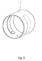
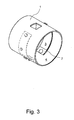
- Fig. 2 and 3 show the measuring electrodes 3 strip-like. They have a length - in the circumferential direction of the measuring line 1 - from slightly less than a quarter of the Meß effetss to slightly more than half of the Meß effetselless, and they have direct, ie electrically conductive, so galvanic contact with the flowing medium.
- the measuring electrodes 3 made of the same material or a similar material as the cover layer 4 and the material of the measuring electrodes 3 has a much higher electrical conductivity than the material of the cover layer 4.
- the electrical conductivity of the material of the measuring electrodes 3 in the radial direction, in the flow direction of the flowing medium and in the direction of Meß einshuss is the same.
- a magnetic-inductive flowmeter further applies that the electrical conductivity of the material of the measuring electrodes 3 by a special chemical and / or physical treatment and / or increased by at least one additive. It is also important that the electrical conductivity of the material of the measuring electrodes 3 by about two times to about ten times higher than the electrical conductivity of the flowing medium.
- Fig. 2 and Fig. 3 - Are the measuring electrodes 3 over their entire length - in the circumferential direction of the measuring line 1 - in one piece.
- a magnetic-inductive flowmeter which has two measuring electrodes 3.
- still reference electrodes 7 to be realized. This is especially true when the magneto-inductive flowmeter according to the invention not only for flow measurement of a flowing medium, but also for conductivity measurement, for level measurement or for conductivity measurement and level measurement or only for conductivity measurement, only for level measurement or only for conductivity measurement and level measurement should be used, which is also possible without further notice.
- the tapping of the measuring medium induced in the flowing medium and detected by the measuring electrodes 3 takes place galvanically.
- the measuring electrodes 3 are each assigned an outwardly leading terminal element 8.
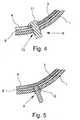
- Fig. 4 this is realized in detail so that the measuring electrodes 3, the cover layer 4 and the measuring line 1 each have a through hole 9 and the connecting elements 8 are guided through the through holes 9 of the measuring electrodes 3, the cover layer 4 and the measuring line 1.
- the terminal elements 8 are provided with a lie in the interior of the measuring line 1 on the measuring electrodes 3, lenticular head.
- the shows Fig. 5 a realization of the galvanic tapping of the induced in the flowing medium and detected by the measuring electrodes 3 measuring voltage, which is characterized in that the measuring electrodes 3 are provided with the cover layer 4 and the measuring line 1 penetrating, circular cylindrical terminal receptacles.
- the connecting elements 8 are bolt-shaped and inserted into the terminal receptacles 11 of the measuring electrodes 3.
Landscapes
- Physics & Mathematics (AREA)
- Fluid Mechanics (AREA)
- General Physics & Mathematics (AREA)
- Electromagnetism (AREA)
- Measuring Volume Flow (AREA)
Applications Claiming Priority (1)
| Application Number | Priority Date | Filing Date | Title |
|---|---|---|---|
| DE102008059067A DE102008059067A1 (de) | 2008-11-26 | 2008-11-26 | Magnetisch-induktives Durchflußmeßgerät |
Publications (3)
| Publication Number | Publication Date |
|---|---|
| EP2192390A2 true EP2192390A2 (fr) | 2010-06-02 |
| EP2192390A3 EP2192390A3 (fr) | 2010-07-07 |
| EP2192390B1 EP2192390B1 (fr) | 2021-06-16 |
Family
ID=41727491
Family Applications (1)
| Application Number | Title | Priority Date | Filing Date |
|---|---|---|---|
| EP09014554.1A Active EP2192390B1 (fr) | 2008-11-26 | 2009-11-23 | Débitmètre à induction magnétique |
Country Status (5)
| Country | Link |
|---|---|
| US (1) | US8074525B2 (fr) |
| EP (1) | EP2192390B1 (fr) |
| JP (1) | JP5822431B2 (fr) |
| CN (1) | CN101900583B (fr) |
| DE (1) | DE102008059067A1 (fr) |
Cited By (7)
| Publication number | Priority date | Publication date | Assignee | Title |
|---|---|---|---|---|
| WO2014019888A1 (fr) * | 2012-07-31 | 2014-02-06 | Ifm Electronic Gmbh | Débitmètre magnéto-inductif |
| EP2700912A3 (fr) * | 2012-08-21 | 2014-07-02 | Krohne AG | Appareil de mesure de débit à induction magnétique et son procédé de fabrication |
| WO2016020277A1 (fr) * | 2014-08-04 | 2016-02-11 | Endress+Hauser Flowtec Ag | Débitmètre à induction magnétique comprenant plusieurs paires d'électrodes de mesure et divers segments transversaux de tubes de mesure |
| DE102014114289A1 (de) | 2014-10-01 | 2016-04-07 | Endress+Hauser Flowtec Ag | Messrohres für ein Durchflussmessgerät, ein Verfahren zur Herstellung eines Messrohres und ein magnetisch-induktives Durchflussmessgerät |
| WO2016164881A1 (fr) | 2015-04-10 | 2016-10-13 | Covar Applied Technologies, Inc. | Mesure de la hauteur d'un flux d'écoulement capacitif discret pour conduits partiellement remplis |
| EP2647969A3 (fr) * | 2012-04-05 | 2017-06-07 | Krohne AG | Débitmètre à induction magnétique |
| WO2022028854A1 (fr) * | 2020-08-04 | 2022-02-10 | Endress+Hauser Flowtec Ag | Dispositif d'automatisation de terrain |
Families Citing this family (26)
| Publication number | Priority date | Publication date | Assignee | Title |
|---|---|---|---|---|
| DE102010032270B4 (de) * | 2010-07-26 | 2016-02-18 | Krohne Ag | Magnetisch-induktives Durchflussmessgerät |
| DE102010056077A1 (de) * | 2010-12-23 | 2012-06-28 | Abb Technology Ag | Magnetisch-induktiver Durchflussmesser mit einer innenwandseitig des Messrohres angeordneten Auskleidung |
| DE102011104799B4 (de) * | 2011-06-06 | 2013-04-25 | Krohne Messtechnik Gmbh | Magnetisch-induktives Durchflussmessgerät und Verfahren zu dessen Betreiben |
| DE102011119982A1 (de) * | 2011-12-02 | 2013-06-06 | Krohne Ag | Magnetisch-induktives Durchflussmessgerät |
| US8991264B2 (en) * | 2012-09-26 | 2015-03-31 | Rosemount Inc. | Integrally molded magnetic flowmeter |
| US9021890B2 (en) | 2012-09-26 | 2015-05-05 | Rosemount Inc. | Magnetic flowmeter with multiple coils |
| CN103196503B (zh) * | 2013-02-22 | 2015-03-25 | 孙晓君 | 一种流量计 |
| US9068869B2 (en) | 2013-03-14 | 2015-06-30 | Rosemount Inc. | Magnetic flowmeter with bonded PTFE electrodes |
| TWI489103B (zh) * | 2013-12-09 | 2015-06-21 | Metal Ind Res & Dev Ct | Fluid cooling system and liquid fluid detection joint and measuring device |
| DE102014113408A1 (de) * | 2014-09-17 | 2016-03-17 | Endress + Hauser Flowtec Ag | Verfahren zur Herstellung eines Magnetisch-induktives Durchfluss- messgeräts mit zum Teil reduziertem Querschnitt |
| DE102014113843A1 (de) | 2014-09-24 | 2016-03-24 | Endress+Hauser Flowtec Ag | Messrohr für ein Durchflussmessgerät und ein magnetisch-induktives Durchflussmessgerät |
| DE102015116676A1 (de) | 2015-01-20 | 2016-07-21 | Krohne Ag | Magnetisch-induktives Durchflussmessgerät und Verfahren zum Herstellen einer Messelektrode |
| EP3048431B1 (fr) | 2015-01-20 | 2020-07-29 | Krohne AG | Débitmètre magnéto-inductif et procédé de fabrication d'une électrode de mesure |
| DE102015112018B3 (de) * | 2015-07-23 | 2016-07-14 | Endress+Hauser Flowtec Ag | Magnetisch-induktives Durchflussmessgerät zur Messung der Durchflussgeschwindigkeit oder dem Volumendurchfluss von Medien in einer Rohrleitung und Verfahren zur Herstellung eines solchen Durchflussmessgeräts |
| EP3517899A4 (fr) * | 2017-04-28 | 2019-08-28 | Aichi Tokei Denki Co., Ltd. | Débitmètre électromagnétique |
| WO2019108719A1 (fr) * | 2017-11-29 | 2019-06-06 | Dm3D Technology, Llc | Appareil de mesure de débit massique d'une poudre pour dépôt de métal direct |
| CN108801374A (zh) * | 2018-06-01 | 2018-11-13 | 重庆川仪自动化股份有限公司 | 一种提高电磁流量性能的流道结构 |
| DE102018114180A1 (de) * | 2018-06-13 | 2019-12-19 | Endress + Hauser Flowtec Ag | Durchflussmessgerät, insbesondere magnetisch-induktives Durchflussmessgerät |
| DE102018115629A1 (de) * | 2018-06-28 | 2020-01-02 | Endress+Hauser Flowtec Ag | Magnetisch-induktives Durchflussmessgerät und ein Verfahren, zum Herstellen eines solchen magnetisch-induktiven Durchfluss-messgerätes |
| US11365995B2 (en) * | 2018-09-28 | 2022-06-21 | Georg Fischer Signet Llc | Magnetic flowmeter including auxiliary electrodes upstream and downstream of the pair of measuring electrodes and an adjustable brace |
| DE102018131167A1 (de) | 2018-12-06 | 2020-06-10 | Endress+Hauser Flowtec Ag | Magnetisch-induktives Durchflussmessgerät |
| GB201911971D0 (en) * | 2019-08-21 | 2019-10-02 | Sentec Ltd | Improved electrode |
| DE102019134440A1 (de) * | 2019-12-16 | 2021-06-17 | Endress + Hauser Wetzer Gmbh + Co. Kg | Messgerät |
| CN115790776B (zh) * | 2022-10-28 | 2025-12-30 | 重庆川仪自动化股份有限公司 | 一种用于非满管电磁流量计的泥位检测装置 |
| DE102022134109A1 (de) * | 2022-12-20 | 2024-06-20 | Endress+Hauser Flowtec Ag | Magnetisch-induktives Durchflussmessgerät |
| DE102023113189A1 (de) * | 2023-05-19 | 2024-11-21 | Krohne Ag | Verfahren zur Oberflächenbehandlung von in ein Messrohr für magnetisch-induktive Durchflussmessgeräte eingesetzte Messelektroden |
Citations (5)
| Publication number | Priority date | Publication date | Assignee | Title |
|---|---|---|---|---|
| EP0608793A2 (fr) | 1993-01-27 | 1994-08-03 | TURBO-WERK Messtechnik GmbH | Débitmètre électromagnétique |
| DE4327826A1 (de) | 1993-08-16 | 1995-03-16 | Ikosta Gmbh Inst Fuer Korrosio | Magnetische Flüssigkeit |
| DE102004057696A1 (de) | 2004-11-30 | 2006-06-08 | Abb Patent Gmbh | Magnetisch induktiver Durchflussmesser mit elektrisch isoliertem Messrohr |
| DE102006026310A1 (de) | 2006-06-02 | 2007-12-06 | Endress + Hauser Flowtec Ag | In-Line-Meßgerät mit einem innen mit Polyurethan ausgekleidetem Meßrohr und Verfahren zu dessen Herstellung |
| DE102006026311A1 (de) | 2006-06-02 | 2007-12-06 | Endress + Hauser Flowtec Ag | In-Line-Meßgerät mit einem innen mit Polyurethan ausgekleidetem Meßrohr und Verfahren zu dessen Herstellung |
Family Cites Families (30)
| Publication number | Priority date | Publication date | Assignee | Title |
|---|---|---|---|---|
| US4036052A (en) * | 1976-07-30 | 1977-07-19 | Fischer & Porter Co. | Electromagnetic flowmeter usable in less-than-full fluid lines |
| JPS53142364U (fr) * | 1977-04-15 | 1978-11-10 | ||
| DE2816796A1 (de) * | 1978-04-18 | 1979-10-25 | Fischer & Porter Gmbh | Magnetisch induktiver durchflussmesser |
| DE2950039C2 (de) * | 1979-12-13 | 1982-11-25 | Krohne Meßtechnik GmbH & Co KG, 4100 Duisburg | Elektroden für elektromagnetische Durchflußmesser |
| US4388834A (en) * | 1981-03-31 | 1983-06-21 | Fischer & Porter Company | Electromagnetic flowmeter having a monolithic conduit |
| JPS57171531U (fr) * | 1981-04-23 | 1982-10-28 | ||
| US4565619A (en) * | 1983-02-18 | 1986-01-21 | The Foxboro Company | Composite electrode structure |
| JPS60104721U (ja) * | 1983-12-22 | 1985-07-17 | 株式会社東芝 | 電磁流量計検出器 |
| JPS6398520A (ja) * | 1986-10-15 | 1988-04-30 | Yokogawa Electric Corp | 電磁流量計の電極部の製造方法 |
| EP0274768A1 (fr) | 1986-11-25 | 1988-07-20 | Pumptech N.V. | Débitmètre électromagnétique pour fluides conductifs ou diélectriques et son application en particulier dans la pétrochimie |
| GB2236394B (en) * | 1989-09-26 | 1994-08-24 | Foxboro Co | Improvements in and relating to electromagnetic flowmeters |
| DE4013634C2 (de) * | 1990-04-27 | 2002-08-01 | Abb Patent Gmbh | Magnetisch induktiver Durchflußaufnehmer |
| DE4139915A1 (de) * | 1991-02-04 | 1992-08-13 | Krohne Messtechnik Kg | Magnetisch-induktiver durchflussmesser |
| JP2599322B2 (ja) * | 1991-10-09 | 1997-04-09 | 山武ハネウエル株式会社 | 電磁流量計用電極の製造方法 |
| DE4243077C2 (de) * | 1991-12-19 | 1994-06-09 | Ultrakust Electronic Gmbh | Verfahren und Vorrichtung zur Entnahme einer repräsentativen Milchprobe |
| DE4317366C2 (de) | 1993-05-25 | 1997-04-17 | Ultrakust Electronic Gmbh | Verfahren und Vorrichtung zur Bestimmung eines Volumenstromes |
| JPH07243885A (ja) * | 1994-03-01 | 1995-09-19 | Yokogawa Electric Corp | 直流励磁電磁流量計 |
| EP0762084A3 (fr) * | 1995-09-12 | 1998-04-22 | Georg Fischer Rohrleitungssysteme AG | Débimètre électromagnétique |
| EP0892252B1 (fr) * | 1995-10-18 | 2011-12-21 | Endress + Hauser Flowtec AG | Electrodes galvaniques des débimètres électromagnétiques |
| DE19637761A1 (de) | 1996-09-16 | 1998-03-19 | Kannegiesser Kmh Kunststofftec | Verfahren und Vorrichtung zum Dosieren eines plastifizierten Kunststoffs |
| JPH10253411A (ja) * | 1997-03-06 | 1998-09-25 | Yokogawa Electric Corp | 低導電率電磁流量計 |
| DE19752368C1 (de) | 1997-11-26 | 2000-01-05 | D T I Dr Trippe Ingenieurgesel | Verfahren zur magnetisch-induktiven Durchflußmessung in Kanalisationen, insbesondere in teilgefüllten Rohren, Gerinnen oder dergleichen, sowie magnetisch-induktiver Durchflußmesser zur Durchführung des Verfahrens |
| DE59814203D1 (de) * | 1998-07-27 | 2008-05-15 | Flowtec Ag | Verfahren zum Zusammenbau einer Elektrodenanordnung für magnetisch-induktive Durchflussaufnehmer |
| GB2385667A (en) | 2002-02-26 | 2003-08-27 | Danfoss As | Insert for an inductive flowmeter |
| GB2403016B (en) * | 2003-06-17 | 2007-02-21 | Abb Ltd | Electromagnetic flow meter |
| DE202004019442U1 (de) * | 2004-12-16 | 2005-03-10 | Bartec Gmbh | Vorrichtung zum Bestimmen des Füllgrades eines Fluides |
| DE102005019418B4 (de) * | 2005-04-25 | 2007-03-15 | Krohne Messtechnik Gmbh & Co. Kg | Magnetisch-induktives Durchflußmeßgerät und Verfahren zur Herstellung eines magnetisch-induktiven Durchflußmeßgeräts |
| DE102005044677A1 (de) | 2005-09-19 | 2007-03-29 | Abb Patent Gmbh | Magnetisch-induktiver Durchflussmesser mit einer Erdungsscheibe |
| DE102007003614A1 (de) | 2006-07-26 | 2008-01-31 | Endress + Hauser Flowtec Ag | Vorrichtung zum Messen des Volumen- oder Massestroms eines Mediums in einer Rohrleitung |
| DE102007005898A1 (de) * | 2007-02-01 | 2008-08-07 | Endress + Hauser Flowtec Ag | Vorrichtung zum Messen des Volumen- oder Massestroms eines Mediums in einer Rohrleitung |
-
2008
- 2008-11-26 DE DE102008059067A patent/DE102008059067A1/de not_active Withdrawn
-
2009
- 2009-11-23 EP EP09014554.1A patent/EP2192390B1/fr active Active
- 2009-11-25 US US12/625,674 patent/US8074525B2/en active Active
- 2009-11-26 JP JP2009268359A patent/JP5822431B2/ja not_active Expired - Fee Related
- 2009-11-26 CN CN2009102584406A patent/CN101900583B/zh not_active Expired - Fee Related
Patent Citations (5)
| Publication number | Priority date | Publication date | Assignee | Title |
|---|---|---|---|---|
| EP0608793A2 (fr) | 1993-01-27 | 1994-08-03 | TURBO-WERK Messtechnik GmbH | Débitmètre électromagnétique |
| DE4327826A1 (de) | 1993-08-16 | 1995-03-16 | Ikosta Gmbh Inst Fuer Korrosio | Magnetische Flüssigkeit |
| DE102004057696A1 (de) | 2004-11-30 | 2006-06-08 | Abb Patent Gmbh | Magnetisch induktiver Durchflussmesser mit elektrisch isoliertem Messrohr |
| DE102006026310A1 (de) | 2006-06-02 | 2007-12-06 | Endress + Hauser Flowtec Ag | In-Line-Meßgerät mit einem innen mit Polyurethan ausgekleidetem Meßrohr und Verfahren zu dessen Herstellung |
| DE102006026311A1 (de) | 2006-06-02 | 2007-12-06 | Endress + Hauser Flowtec Ag | In-Line-Meßgerät mit einem innen mit Polyurethan ausgekleidetem Meßrohr und Verfahren zu dessen Herstellung |
Cited By (9)
| Publication number | Priority date | Publication date | Assignee | Title |
|---|---|---|---|---|
| EP2647969A3 (fr) * | 2012-04-05 | 2017-06-07 | Krohne AG | Débitmètre à induction magnétique |
| WO2014019888A1 (fr) * | 2012-07-31 | 2014-02-06 | Ifm Electronic Gmbh | Débitmètre magnéto-inductif |
| EP2700912A3 (fr) * | 2012-08-21 | 2014-07-02 | Krohne AG | Appareil de mesure de débit à induction magnétique et son procédé de fabrication |
| RU2590230C2 (ru) * | 2012-08-21 | 2016-07-10 | Кроне Аг | Способ изготовления магнитно-индуктивного расходомера |
| WO2016020277A1 (fr) * | 2014-08-04 | 2016-02-11 | Endress+Hauser Flowtec Ag | Débitmètre à induction magnétique comprenant plusieurs paires d'électrodes de mesure et divers segments transversaux de tubes de mesure |
| DE102014114289A1 (de) | 2014-10-01 | 2016-04-07 | Endress+Hauser Flowtec Ag | Messrohres für ein Durchflussmessgerät, ein Verfahren zur Herstellung eines Messrohres und ein magnetisch-induktives Durchflussmessgerät |
| WO2016164881A1 (fr) | 2015-04-10 | 2016-10-13 | Covar Applied Technologies, Inc. | Mesure de la hauteur d'un flux d'écoulement capacitif discret pour conduits partiellement remplis |
| EP3280983A4 (fr) * | 2015-04-10 | 2019-01-02 | CoVar Applied Technologies, Inc. | Mesure de la hauteur d'un flux d'écoulement capacitif discret pour conduits partiellement remplis |
| WO2022028854A1 (fr) * | 2020-08-04 | 2022-02-10 | Endress+Hauser Flowtec Ag | Dispositif d'automatisation de terrain |
Also Published As
| Publication number | Publication date |
|---|---|
| JP5822431B2 (ja) | 2015-11-24 |
| CN101900583B (zh) | 2013-06-05 |
| EP2192390A3 (fr) | 2010-07-07 |
| US20100132479A1 (en) | 2010-06-03 |
| US8074525B2 (en) | 2011-12-13 |
| JP2010127939A (ja) | 2010-06-10 |
| CN101900583A (zh) | 2010-12-01 |
| EP2192390B1 (fr) | 2021-06-16 |
| DE102008059067A1 (de) | 2010-06-02 |
Similar Documents
| Publication | Publication Date | Title |
|---|---|---|
| EP2192390B1 (fr) | Débitmètre à induction magnétique | |
| DE102010001993B4 (de) | Magnetisch-induktives Durchflussmessgerät | |
| EP2700912B1 (fr) | Appareil de mesure de débit à induction magnétique et son procédé de fabrication | |
| DE102007038895A1 (de) | Durchflussmessgerät | |
| EP1666849A1 (fr) | Débimètre électro-magnétique et sa méthode de fabrication | |
| DE102010030229A1 (de) | Verfahren zur Herstellung eines magnetisch-induktiven Durchflussmessgeräts | |
| EP2687827B1 (fr) | Débitmètre à induction magnétique | |
| DE102011119982A1 (de) | Magnetisch-induktives Durchflussmessgerät | |
| DE102017115139A1 (de) | Messrohr und Messrohr zur Bestimmung und/oder Überwachung zumindest einer Prozessgröße eines Mediums | |
| DE102015116679A1 (de) | Magnetisch-induktives Durchflussmessgerät | |
| DE102005044677A1 (de) | Magnetisch-induktiver Durchflussmesser mit einer Erdungsscheibe | |
| EP3058317B1 (fr) | Système magnétique-inductif pour mesurer un débit | |
| DE202008002816U1 (de) | Vorrichtung zur Durchflussmessung | |
| DE102005009675B3 (de) | Durchflußmeßgerät | |
| DE102009031873A1 (de) | Magnetisch induktiver Durchflussmesser sowie austauschbarer rohrförmiger Einsatz für einen derartigen Durchflussmesser | |
| DE102006000814A1 (de) | Magnetisch-induktives Durchflußmeßgerät | |
| DE102016121643A1 (de) | Messanordnung zur Bestimmung und/oder Überwachung zumindest einer Prozessgröße eines Mediums in einer Rohrleitung | |
| DE102006008451B4 (de) | Magnetisch-induktiver Durchflussmesser mit einem Messrohr aus Metall | |
| DE102011009062A1 (de) | Magnetkreisvorrichtung für ein magnetisch-induktives Durchflussmessgerät | |
| DE102008054432A1 (de) | Messeinrichtung mit einem Messrohr und Verfahren zur Überwachung der Messeinrichtung sowie Vorrichtung zur Überwachung einer Rohrleitung | |
| EP0179285B2 (fr) | Débitmètre magnéto-inductif | |
| DE102014001479B4 (de) | Magenetisch-induktives Durchflussmessgerät | |
| DE202012004630U1 (de) | Betonrohr mit aus Kunststoff bestehender Außenauskleidung | |
| DE102016014778A1 (de) | Vorrichtung zum Anzeigen und/oder Kontrollieren von Fluidzuständen | |
| DE102015116676A1 (de) | Magnetisch-induktives Durchflussmessgerät und Verfahren zum Herstellen einer Messelektrode |
Legal Events
| Date | Code | Title | Description |
|---|---|---|---|
| PUAI | Public reference made under article 153(3) epc to a published international application that has entered the european phase |
Free format text: ORIGINAL CODE: 0009012 |
|
| AK | Designated contracting states |
Kind code of ref document: A2 Designated state(s): AT BE BG CH CY CZ DE DK EE ES FI FR GB GR HR HU IE IS IT LI LT LU LV MC MK MT NL NO PL PT RO SE SI SK SM TR |
|
| AX | Request for extension of the european patent |
Extension state: AL BA RS |
|
| PUAL | Search report despatched |
Free format text: ORIGINAL CODE: 0009013 |
|
| AK | Designated contracting states |
Kind code of ref document: A3 Designated state(s): AT BE BG CH CY CZ DE DK EE ES FI FR GB GR HR HU IE IS IT LI LT LU LV MC MK MT NL NO PL PT RO SE SI SK SM TR |
|
| AX | Request for extension of the european patent |
Extension state: AL BA RS |
|
| 17P | Request for examination filed |
Effective date: 20101206 |
|
| 17Q | First examination report despatched |
Effective date: 20130906 |
|
| STAA | Information on the status of an ep patent application or granted ep patent |
Free format text: STATUS: EXAMINATION IS IN PROGRESS |
|
| GRAP | Despatch of communication of intention to grant a patent |
Free format text: ORIGINAL CODE: EPIDOSNIGR1 |
|
| STAA | Information on the status of an ep patent application or granted ep patent |
Free format text: STATUS: GRANT OF PATENT IS INTENDED |
|
| GRAJ | Information related to disapproval of communication of intention to grant by the applicant or resumption of examination proceedings by the epo deleted |
Free format text: ORIGINAL CODE: EPIDOSDIGR1 |
|
| STAA | Information on the status of an ep patent application or granted ep patent |
Free format text: STATUS: EXAMINATION IS IN PROGRESS |
|
| INTG | Intention to grant announced |
Effective date: 20201214 |
|
| GRAP | Despatch of communication of intention to grant a patent |
Free format text: ORIGINAL CODE: EPIDOSNIGR1 |
|
| STAA | Information on the status of an ep patent application or granted ep patent |
Free format text: STATUS: GRANT OF PATENT IS INTENDED |
|
| INTC | Intention to grant announced (deleted) | ||
| INTG | Intention to grant announced |
Effective date: 20210204 |
|
| GRAS | Grant fee paid |
Free format text: ORIGINAL CODE: EPIDOSNIGR3 |
|
| GRAA | (expected) grant |
Free format text: ORIGINAL CODE: 0009210 |
|
| STAA | Information on the status of an ep patent application or granted ep patent |
Free format text: STATUS: THE PATENT HAS BEEN GRANTED |
|
| AK | Designated contracting states |
Kind code of ref document: B1 Designated state(s): AT BE BG CH CY CZ DE DK EE ES FI FR GB GR HR HU IE IS IT LI LT LU LV MC MK MT NL NO PL PT RO SE SI SK SM TR |
|
| REG | Reference to a national code |
Ref country code: GB Ref legal event code: FG4D Free format text: NOT ENGLISH |
|
| REG | Reference to a national code |
Ref country code: CH Ref legal event code: EP |
|
| REG | Reference to a national code |
Ref country code: DE Ref legal event code: R096 Ref document number: 502009016373 Country of ref document: DE |
|
| REG | Reference to a national code |
Ref country code: AT Ref legal event code: REF Ref document number: 1402712 Country of ref document: AT Kind code of ref document: T Effective date: 20210715 |
|
| REG | Reference to a national code |
Ref country code: IE Ref legal event code: FG4D Free format text: LANGUAGE OF EP DOCUMENT: GERMAN |
|
| REG | Reference to a national code |
Ref country code: DE Ref legal event code: R231 Ref document number: 502009016373 Country of ref document: DE |
|
| REG | Reference to a national code |
Ref country code: LT Ref legal event code: MG9D |
|
| PG25 | Lapsed in a contracting state [announced via postgrant information from national office to epo] |
Ref country code: LT Free format text: LAPSE BECAUSE OF FAILURE TO SUBMIT A TRANSLATION OF THE DESCRIPTION OR TO PAY THE FEE WITHIN THE PRESCRIBED TIME-LIMIT Effective date: 20210616 Ref country code: FI Free format text: LAPSE BECAUSE OF FAILURE TO SUBMIT A TRANSLATION OF THE DESCRIPTION OR TO PAY THE FEE WITHIN THE PRESCRIBED TIME-LIMIT Effective date: 20210616 Ref country code: BG Free format text: LAPSE BECAUSE OF FAILURE TO SUBMIT A TRANSLATION OF THE DESCRIPTION OR TO PAY THE FEE WITHIN THE PRESCRIBED TIME-LIMIT Effective date: 20210916 Ref country code: HR Free format text: LAPSE BECAUSE OF FAILURE TO SUBMIT A TRANSLATION OF THE DESCRIPTION OR TO PAY THE FEE WITHIN THE PRESCRIBED TIME-LIMIT Effective date: 20210616 |
|
| REG | Reference to a national code |
Ref country code: NL Ref legal event code: MP Effective date: 20210616 |
|
| PG25 | Lapsed in a contracting state [announced via postgrant information from national office to epo] |
Ref country code: LV Free format text: LAPSE BECAUSE OF FAILURE TO SUBMIT A TRANSLATION OF THE DESCRIPTION OR TO PAY THE FEE WITHIN THE PRESCRIBED TIME-LIMIT Effective date: 20210616 Ref country code: GR Free format text: LAPSE BECAUSE OF FAILURE TO SUBMIT A TRANSLATION OF THE DESCRIPTION OR TO PAY THE FEE WITHIN THE PRESCRIBED TIME-LIMIT Effective date: 20210917 Ref country code: SE Free format text: LAPSE BECAUSE OF FAILURE TO SUBMIT A TRANSLATION OF THE DESCRIPTION OR TO PAY THE FEE WITHIN THE PRESCRIBED TIME-LIMIT Effective date: 20210616 Ref country code: NO Free format text: LAPSE BECAUSE OF FAILURE TO SUBMIT A TRANSLATION OF THE DESCRIPTION OR TO PAY THE FEE WITHIN THE PRESCRIBED TIME-LIMIT Effective date: 20210916 Ref country code: DE Free format text: LAPSE BECAUSE OF THE APPLICANT RENOUNCES Effective date: 20210927 |
|
| PG25 | Lapsed in a contracting state [announced via postgrant information from national office to epo] |
Ref country code: RO Free format text: LAPSE BECAUSE OF FAILURE TO SUBMIT A TRANSLATION OF THE DESCRIPTION OR TO PAY THE FEE WITHIN THE PRESCRIBED TIME-LIMIT Effective date: 20210616 Ref country code: NL Free format text: LAPSE BECAUSE OF FAILURE TO SUBMIT A TRANSLATION OF THE DESCRIPTION OR TO PAY THE FEE WITHIN THE PRESCRIBED TIME-LIMIT Effective date: 20210616 Ref country code: PT Free format text: LAPSE BECAUSE OF FAILURE TO SUBMIT A TRANSLATION OF THE DESCRIPTION OR TO PAY THE FEE WITHIN THE PRESCRIBED TIME-LIMIT Effective date: 20211018 Ref country code: ES Free format text: LAPSE BECAUSE OF FAILURE TO SUBMIT A TRANSLATION OF THE DESCRIPTION OR TO PAY THE FEE WITHIN THE PRESCRIBED TIME-LIMIT Effective date: 20210616 Ref country code: CZ Free format text: LAPSE BECAUSE OF FAILURE TO SUBMIT A TRANSLATION OF THE DESCRIPTION OR TO PAY THE FEE WITHIN THE PRESCRIBED TIME-LIMIT Effective date: 20210616 Ref country code: EE Free format text: LAPSE BECAUSE OF FAILURE TO SUBMIT A TRANSLATION OF THE DESCRIPTION OR TO PAY THE FEE WITHIN THE PRESCRIBED TIME-LIMIT Effective date: 20210616 Ref country code: SM Free format text: LAPSE BECAUSE OF FAILURE TO SUBMIT A TRANSLATION OF THE DESCRIPTION OR TO PAY THE FEE WITHIN THE PRESCRIBED TIME-LIMIT Effective date: 20210616 Ref country code: SK Free format text: LAPSE BECAUSE OF FAILURE TO SUBMIT A TRANSLATION OF THE DESCRIPTION OR TO PAY THE FEE WITHIN THE PRESCRIBED TIME-LIMIT Effective date: 20210616 |
|
| PG25 | Lapsed in a contracting state [announced via postgrant information from national office to epo] |
Ref country code: PL Free format text: LAPSE BECAUSE OF FAILURE TO SUBMIT A TRANSLATION OF THE DESCRIPTION OR TO PAY THE FEE WITHIN THE PRESCRIBED TIME-LIMIT Effective date: 20210616 |
|
| PLBE | No opposition filed within time limit |
Free format text: ORIGINAL CODE: 0009261 |
|
| STAA | Information on the status of an ep patent application or granted ep patent |
Free format text: STATUS: NO OPPOSITION FILED WITHIN TIME LIMIT |
|
| PG25 | Lapsed in a contracting state [announced via postgrant information from national office to epo] |
Ref country code: DK Free format text: LAPSE BECAUSE OF FAILURE TO SUBMIT A TRANSLATION OF THE DESCRIPTION OR TO PAY THE FEE WITHIN THE PRESCRIBED TIME-LIMIT Effective date: 20210616 |
|
| 26N | No opposition filed |
Effective date: 20220317 |
|
| PG25 | Lapsed in a contracting state [announced via postgrant information from national office to epo] |
Ref country code: MC Free format text: LAPSE BECAUSE OF FAILURE TO SUBMIT A TRANSLATION OF THE DESCRIPTION OR TO PAY THE FEE WITHIN THE PRESCRIBED TIME-LIMIT Effective date: 20210616 |
|
| REG | Reference to a national code |
Ref country code: CH Ref legal event code: PL |
|
| GBPC | Gb: european patent ceased through non-payment of renewal fee |
Effective date: 20211123 |
|
| PG25 | Lapsed in a contracting state [announced via postgrant information from national office to epo] |
Ref country code: LU Free format text: LAPSE BECAUSE OF NON-PAYMENT OF DUE FEES Effective date: 20211123 Ref country code: IT Free format text: LAPSE BECAUSE OF FAILURE TO SUBMIT A TRANSLATION OF THE DESCRIPTION OR TO PAY THE FEE WITHIN THE PRESCRIBED TIME-LIMIT Effective date: 20210616 Ref country code: BE Free format text: LAPSE BECAUSE OF NON-PAYMENT OF DUE FEES Effective date: 20211130 |
|
| REG | Reference to a national code |
Ref country code: BE Ref legal event code: MM Effective date: 20211130 |
|
| PG25 | Lapsed in a contracting state [announced via postgrant information from national office to epo] |
Ref country code: LI Free format text: LAPSE BECAUSE OF NON-PAYMENT OF DUE FEES Effective date: 20211130 Ref country code: CH Free format text: LAPSE BECAUSE OF NON-PAYMENT OF DUE FEES Effective date: 20211130 |
|
| PG25 | Lapsed in a contracting state [announced via postgrant information from national office to epo] |
Ref country code: IE Free format text: LAPSE BECAUSE OF NON-PAYMENT OF DUE FEES Effective date: 20211123 Ref country code: GB Free format text: LAPSE BECAUSE OF NON-PAYMENT OF DUE FEES Effective date: 20211123 |
|
| PG25 | Lapsed in a contracting state [announced via postgrant information from national office to epo] |
Ref country code: FR Free format text: LAPSE BECAUSE OF NON-PAYMENT OF DUE FEES Effective date: 20211130 |
|
| REG | Reference to a national code |
Ref country code: AT Ref legal event code: MM01 Ref document number: 1402712 Country of ref document: AT Kind code of ref document: T Effective date: 20211123 |
|
| PG25 | Lapsed in a contracting state [announced via postgrant information from national office to epo] |
Ref country code: AT Free format text: LAPSE BECAUSE OF NON-PAYMENT OF DUE FEES Effective date: 20211123 |
|
| PG25 | Lapsed in a contracting state [announced via postgrant information from national office to epo] |
Ref country code: HU Free format text: LAPSE BECAUSE OF FAILURE TO SUBMIT A TRANSLATION OF THE DESCRIPTION OR TO PAY THE FEE WITHIN THE PRESCRIBED TIME-LIMIT; INVALID AB INITIO Effective date: 20091123 Ref country code: CY Free format text: LAPSE BECAUSE OF FAILURE TO SUBMIT A TRANSLATION OF THE DESCRIPTION OR TO PAY THE FEE WITHIN THE PRESCRIBED TIME-LIMIT Effective date: 20210616 |
|
| PG25 | Lapsed in a contracting state [announced via postgrant information from national office to epo] |
Ref country code: MK Free format text: LAPSE BECAUSE OF FAILURE TO SUBMIT A TRANSLATION OF THE DESCRIPTION OR TO PAY THE FEE WITHIN THE PRESCRIBED TIME-LIMIT Effective date: 20210616 |
|
| PG25 | Lapsed in a contracting state [announced via postgrant information from national office to epo] |
Ref country code: MT Free format text: LAPSE BECAUSE OF FAILURE TO SUBMIT A TRANSLATION OF THE DESCRIPTION OR TO PAY THE FEE WITHIN THE PRESCRIBED TIME-LIMIT Effective date: 20210616 |
|
| PG25 | Lapsed in a contracting state [announced via postgrant information from national office to epo] |
Ref country code: TR Free format text: LAPSE BECAUSE OF FAILURE TO SUBMIT A TRANSLATION OF THE DESCRIPTION OR TO PAY THE FEE WITHIN THE PRESCRIBED TIME-LIMIT Effective date: 20210616 |