EP2192667A2 - Dispositif d'alimentation en énergie - Google Patents
Dispositif d'alimentation en énergie Download PDFInfo
- Publication number
- EP2192667A2 EP2192667A2 EP09014326A EP09014326A EP2192667A2 EP 2192667 A2 EP2192667 A2 EP 2192667A2 EP 09014326 A EP09014326 A EP 09014326A EP 09014326 A EP09014326 A EP 09014326A EP 2192667 A2 EP2192667 A2 EP 2192667A2
- Authority
- EP
- European Patent Office
- Prior art keywords
- voltage
- factor
- generator
- feed device
- max
- Prior art date
- Legal status (The legal status is an assumption and is not a legal conclusion. Google has not performed a legal analysis and makes no representation as to the accuracy of the status listed.)
- Withdrawn
Links
Images
Classifications
-
- H—ELECTRICITY
- H02—GENERATION; CONVERSION OR DISTRIBUTION OF ELECTRIC POWER
- H02J—ELECTRIC POWER NETWORKS; CIRCUIT ARRANGEMENTS OR SYSTEMS FOR SUPPLYING OR DISTRIBUTING ELECTRIC POWER; SYSTEMS FOR STORING ELECTRIC ENERGY
- H02J3/00—Circuit arrangements for AC mains or AC distribution networks
- H02J3/38—Arrangements for feeding a single network from two or more generators or sources in parallel; Arrangements for feeding already energised networks from additional generators or sources in parallel
- H02J3/381—Dispersed generators
-
- H—ELECTRICITY
- H02—GENERATION; CONVERSION OR DISTRIBUTION OF ELECTRIC POWER
- H02J—ELECTRIC POWER NETWORKS; CIRCUIT ARRANGEMENTS OR SYSTEMS FOR SUPPLYING OR DISTRIBUTING ELECTRIC POWER; SYSTEMS FOR STORING ELECTRIC ENERGY
- H02J2101/00—Supply or distribution of decentralised, dispersed or local electric power generation
- H02J2101/20—Dispersed power generation using renewable energy sources
- H02J2101/22—Solar energy
- H02J2101/24—Photovoltaics
-
- Y—GENERAL TAGGING OF NEW TECHNOLOGICAL DEVELOPMENTS; GENERAL TAGGING OF CROSS-SECTIONAL TECHNOLOGIES SPANNING OVER SEVERAL SECTIONS OF THE IPC; TECHNICAL SUBJECTS COVERED BY FORMER USPC CROSS-REFERENCE ART COLLECTIONS [XRACs] AND DIGESTS
- Y02—TECHNOLOGIES OR APPLICATIONS FOR MITIGATION OR ADAPTATION AGAINST CLIMATE CHANGE
- Y02E—REDUCTION OF GREENHOUSE GAS [GHG] EMISSIONS, RELATED TO ENERGY GENERATION, TRANSMISSION OR DISTRIBUTION
- Y02E10/00—Energy generation through renewable energy sources
- Y02E10/50—Photovoltaic [PV] energy
- Y02E10/56—Power conversion systems, e.g. maximum power point trackers
Definitions
- the present invention relates to a power feeding device, in particular a power feeding device according to the preamble of claim 1, and a method for controlling the operation of such a power feeding device.
- a solar module as an example of a power supply device typically includes a solar generator having at least one solar cell for converting incident radiation into electrical energy, at least one storage capacitor connected in parallel with the solar generator, and a solar inverter for feeding the electrical energy generated by the solar generator into a network or at least one consumer.
- the solar inverter should start with the grid feed as possible, if the power of the solar generator is large enough to compensate for the idling losses of the solar inverter, otherwise the still missing power is taken from the network, causing unnecessary losses.
- a known approach to solving this problem is to switch on the solar inverter only when the solar generator voltage exceeds a predetermined threshold.
- the problem here is that the open circuit voltage of the solar generator says little about its potential power to the grid feed. It may therefore happen that sufficient power is already available below the threshold value, which is not used in this case. On the other hand, it may also be the case that the power of the solar generator despite exceeding the voltage threshold too small (for example, partial shading of the solar cells).
- the solar inverter In order not to draw unnecessary energy from the grid in this constellation, the solar inverter must be switched off again. In unfavorable lighting conditions (eg in rainy weather), this can lead to repeated switching on and off of the solar inverter, which wears out the relays and causes noise.
- the present invention has for its object to provide an improved power supply device which operates the power supply only with sufficient power of the solar generator.
- the energy supply device comprises a generator for generating electrical energy and a feed device for feeding the electrical energy generated by the generator into a network or at least one consumer, the generator being connected in parallel with a pre-load.
- a control device for controlling the operation of the feeding device is arranged to measure a differential voltage between unloaded and preloaded generator, weighting this differential voltage by a factor, and the feeding device only when the weighted ones Differential voltage corresponds to a maximum limit voltage, can operate.
- the factor is not equal to 1, in particular the factor greater than 1 is particularly advantageous.
- a control device for controlling the operation of the feed device, which is designed to measure a differential voltage between unloaded and loaded by the pre-load generator, this difference voltage with a factor, preferably with a factor not equal to 1, in particular with a factor greater to weight as 1 and to operate the feed device only when the weighted differential voltage corresponds to a maximum of a limit voltage.
- This embodiment of the control device ensures in a simple manner that the feed device is activated only when the power of the generator is sufficiently high.
- the energy is fed into the grid or a consumer already at relatively low, but already sufficient power of the generator, so that the effectiveness of the power supply device is increased.
- a relatively accurate forecast of the actual available power is calculated.
- the preload can also be dimensioned much smaller than it corresponds to the self-consumption of the feed device.
- the volume of construction, waste heat and costs of the pre-load are reduced, which is particularly advantageous for larger generator outputs. Furthermore, unnecessary relay switching is prevented.
- the energy supply device can be used advantageously for example in a solar module.
- the generator is a solar generator with at least one solar cell and the feed device is a solar inverter.
- the power feed device may include generators for generating electrical energy from radiation, mechanical energy, kinetic energy, and the like, and may include feeders with or without transformers, with inverters, rectifiers, or without power converter elements.
- the threshold voltage may depend on an open circuit voltage of the generator and / or a minimum required input voltage of the feed device.
- the threshold voltage may be the differential voltage between the open circuit voltage of the generator and the minimum required input voltage of the feeder device.
- the factor may depend on a ratio of a self-consumption power to a pre-load power of the power supply device and / or a load-dependent behavior of the generator.
- the factor may have a fixed value or be a variable factor.
- the factor may be designed as a self-learning factor.
- control device can be integrated in the feed device.
- a power supply device of the invention will be explained in more detail using the example of a solar module. As mentioned above, however, the present invention is not limited to this application.
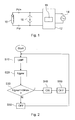
- the solar module includes in known manner a solar generator 10 with at least one solar cell for converting incident radiation into electrical energy and a solar inverter 12 for feeding the energy generated by the solar generator 10 in a network 14 or at least one consumer.
- the solar module is also provided with a preload 16, which is connected in parallel to the solar generator 10 and a possibly also existing storage capacitor.
- This preload 16 may be made weaker than it corresponds to the self-consumption of the inverter 12. This reduces the volume of construction, waste heat and costs for the preload 16 and thus for the entire energy supply device. This is particularly advantageous for large generator powers.
- This energy supply device further has a control device 18 for controlling the operation of the solar module, in particular its inverter 12.
- This control device 18 is preferably integrated in the solar inverter 12 and formed, for example, as a microcontroller.
- the activation or deactivation of the feed device 12 i.
- the solar inverter continuously monitored and controlled by the control device 18 in the manner described below.
- This difference voltage U diff is weighted in a next step S20 with a factor F, preferably the factor F is not equal to 1, in particular the factor F is greater than 1:
- This factor F depends on the ratio of the self-consumption power to the pre-load power as well as the load-dependent generator behavior.
- the self-consumption power and the preload power of the power supply device are predetermined values resulting from the loads connected to the inverter 12 and the dimensioning of the components of the entire device, respectively.
- this factor F is a constant, fixed preset numerical value or a variable variable.
- the factor F can be calculated as a function with operating parameters of the power feeding device. These operating parameters are, for example, the temperature, the mains voltage, etc.
- the factor F can also be designed as a self-learning factor, i. the controller 18 automatically adjusts the factor F over time to optimize it. With a suitable choice of the weighting factor F, the various tolerances of the entire system can also be taken into account.
- the control device 18 compares the determined weighted difference voltage U gew with a limit voltage U max . Is the weighted Difference voltage U gew less than or equal to the threshold voltage U max means that the generator power is sufficiently high to operate the feed device 12. The control device 18 therefore activates the solar inverter 12 in step S40 and deactivates the pre-load 16. If, however, the weighted difference voltage U gew greater than the threshold voltage U max , the solar inverter 12 is not activated by the control device 18 (step S50).
- the control device 18 monitors the input power of the feed device 12. If the input power of the feed device 12 drops to the self-consumption value of the feed device 12, the control device 18 switches off the feed device 12 (step S60), which then becomes standby Operation is located.
- steps S10 to S50 are further repeated during the standby operation of the power feeding device to optimally control the activation of the feeding device 12.
- small energy values are to be fed into the network, if possible, and on the other hand frequent switching on and off of the relays must be avoided.
- the limit voltage U max which is used in step S30 from the controller 18 for comparison with the weighted difference voltage U wt depends empty, for example, from the source load voltage U, ie, from the voltage value of the unloaded generator 10 and the minimum required input voltage U a of the feed 12 from.
- the minimum required input voltage U is a voltage value that can be dynamically changed and are generally dependent on the predetermined network voltage, which is anyway measured continuously by the control device 18 for the purpose of monitoring.
- the power feed device of the invention allows the feeding of itself no power into a network 14 by the feed device 12 is activated at the time when provided by the generator 10 energy equal to or exceeds the self-consumption of the feed device 12. At the same time too frequent switching of the relay is avoided, for example, in fluctuating conditions and generator performance.
- the invention described above is particularly advantageous in power feed devices in which the generators 10 provide fluctuating power, as is the case, for example, with solar generators.
- the energy supply device according to the invention can also be used effectively in transformerless feed devices 12 in an advantageous manner.
Landscapes
- Engineering & Computer Science (AREA)
- Power Engineering (AREA)
- Control Of Electrical Variables (AREA)
- Supply And Distribution Of Alternating Current (AREA)
Applications Claiming Priority (1)
| Application Number | Priority Date | Filing Date | Title |
|---|---|---|---|
| DE102008059428A DE102008059428A1 (de) | 2008-11-27 | 2008-11-27 | Energieeinspeisevorrichtung |
Publications (2)
| Publication Number | Publication Date |
|---|---|
| EP2192667A2 true EP2192667A2 (fr) | 2010-06-02 |
| EP2192667A3 EP2192667A3 (fr) | 2013-12-25 |
Family
ID=41796612
Family Applications (1)
| Application Number | Title | Priority Date | Filing Date |
|---|---|---|---|
| EP09014326.4A Withdrawn EP2192667A3 (fr) | 2008-11-27 | 2009-11-17 | Dispositif d'alimentation en énergie |
Country Status (4)
| Country | Link |
|---|---|
| US (1) | US8378642B2 (fr) |
| EP (1) | EP2192667A3 (fr) |
| CA (1) | CA2686158A1 (fr) |
| DE (1) | DE102008059428A1 (fr) |
Families Citing this family (2)
| Publication number | Priority date | Publication date | Assignee | Title |
|---|---|---|---|---|
| DE102010055486A1 (de) | 2010-12-22 | 2012-06-28 | Diehl Ako Stiftung & Co. Kg | Solarmodul und Verfahren |
| CN106256086B (zh) * | 2014-05-27 | 2019-06-21 | 太阳能公司 | 光伏系统保护 |
Family Cites Families (8)
| Publication number | Priority date | Publication date | Assignee | Title |
|---|---|---|---|---|
| US4333136A (en) * | 1979-11-26 | 1982-06-01 | Baker Richard H | Solar powered automatic turn-on control (SPA-TOC) unit and method |
| US5483147A (en) * | 1992-07-10 | 1996-01-09 | Massachusetts Institute Of Technology | Decentralized excitation control for an electrical power utility system |
| DE69916535T2 (de) * | 1998-07-09 | 2005-05-12 | Sumitomo Chemical Co. Ltd. | Verfahren zur Herstellung eines Titankomplexes |
| US6204642B1 (en) * | 1999-08-06 | 2001-03-20 | General Electric Company | Method and apparatus for modifying limit and protection software in a synchronous generator exciter to match the capability of the turbine-generator |
| US6285168B1 (en) * | 1999-09-30 | 2001-09-04 | Rockwell Automation Technologies, Inc. | Reactive droop compensation system and method |
| DE102007012590B3 (de) * | 2007-03-13 | 2008-11-27 | Diehl Ako Stiftung & Co. Kg | Solarmodul |
| US7570028B2 (en) * | 2007-04-26 | 2009-08-04 | Advanced Energy Industries, Inc. | Method and apparatus for modifying interactions between an electrical generator and a nonlinear load |
| CN101919132B (zh) * | 2007-12-28 | 2013-10-16 | 维斯塔斯风力系统有限公司 | 用于在低市电网电压条件下运行风力涡轮机的设备和方法 |
-
2008
- 2008-11-27 DE DE102008059428A patent/DE102008059428A1/de not_active Ceased
-
2009
- 2009-11-17 EP EP09014326.4A patent/EP2192667A3/fr not_active Withdrawn
- 2009-11-17 CA CA2686158A patent/CA2686158A1/fr not_active Abandoned
- 2009-11-24 US US12/624,810 patent/US8378642B2/en not_active Expired - Fee Related
Also Published As
| Publication number | Publication date |
|---|---|
| DE102008059428A1 (de) | 2010-06-10 |
| EP2192667A3 (fr) | 2013-12-25 |
| US8378642B2 (en) | 2013-02-19 |
| US20100127577A1 (en) | 2010-05-27 |
| CA2686158A1 (fr) | 2010-05-27 |
Similar Documents
| Publication | Publication Date | Title |
|---|---|---|
| EP2872777B1 (fr) | Procédé pour commander un générateur électrique | |
| EP2190110B1 (fr) | Détermination de la capacité de charge d'une source de courant continu pouvant être connectée au réseau sur un interrupteur et un onduleur au réseau | |
| EP0111729B1 (fr) | Montage pour alimenter des usagers électriques avec une tension continue | |
| EP2568547A1 (fr) | Pilote laser sans moniteur à diode | |
| EP2850725B1 (fr) | Procédé de régulation d'une source de courant, source de courant et régulateur de processus associés | |
| DE2551312A1 (de) | Vorrichtung zur kontinuierlichen versorgung mindestens eines verbrauchers mit elektrischer energie | |
| DE102007012590B3 (de) | Solarmodul | |
| DE102014007548A1 (de) | Verfahren zum Betrieb eines Bordnetzes eines Kraftfahrzeugs und Kraftfahrzeug | |
| EP2365599A1 (fr) | Dispositif de conversion d'énergie électrique et procédé de fonctionnement d'un tel dispositif | |
| DE102011054971A1 (de) | Bereitstellung von Regelleistung mit einer Photovoltaikanlage | |
| DE10236025A1 (de) | Elektrische Ladesteuereinrichtung und diese verwendende Lasttreibereinrichtung | |
| EP3097622B1 (fr) | Régulation d'un parc éolien avec comportement amélioré de saut de la valeur de consigne | |
| EP0169461A1 (fr) | Circuit pour alimenter des charges électriques avec une tension continue | |
| WO2018054835A1 (fr) | Module solaire, installation photovoltaïque et procédé de limitation de tension | |
| EP2192667A2 (fr) | Dispositif d'alimentation en énergie | |
| EP2831990A2 (fr) | Procédé de commande d'un système d'alimentation en courant | |
| DE102013202600B4 (de) | Verfahren zur Ertragsoptimierung eines teilverschatteten Photovoltaik-Feldes | |
| EP3297115A1 (fr) | Système comprenant un dispositif d'accumulation d'énergie et un convertisseur d'énergie destiné à recevoir de l'énergie électrique provenant d'un réseau électrique et fournir l'énergie électrique au réseau électrique | |
| DE102019101827A1 (de) | Umrichter und Umrichtungsverfahren | |
| DE102013112988B4 (de) | Verfahren zum Betreiben eines DC/DC-Wandlers, über den ein Photovoltaikmodul mit anderen, eine andere Kennlinie aufweisenden Photovoltaikmodulen in Reihe geschaltet ist, sowie entsprechender DC/DC-Wandler und Photovoltaikgenerator | |
| EP3827516B1 (fr) | Procédé d'utilisation d'une installation photovoltaïque ayant un rendement global amélioré | |
| EP2469601A2 (fr) | Module solaire et procédé | |
| WO2023001365A1 (fr) | Procédé de fonctionnement d'un onduleur, onduleur et système de génération d'énergie comprenant un tel onduleur | |
| DE102020101372A1 (de) | Betriebsverfahren für einen wechselrichter, wechselrichter und energieerzeugungsanlage mit einem derartigen wechselrichter | |
| DE102013105262A1 (de) | Steuervorrichtung für einen Gleichspannungswandler |
Legal Events
| Date | Code | Title | Description |
|---|---|---|---|
| PUAI | Public reference made under article 153(3) epc to a published international application that has entered the european phase |
Free format text: ORIGINAL CODE: 0009012 |
|
| AK | Designated contracting states |
Kind code of ref document: A2 Designated state(s): AT BE BG CH CY CZ DE DK EE ES FI FR GB GR HR HU IE IS IT LI LT LU LV MC MK MT NL NO PL PT RO SE SI SK SM TR |
|
| AX | Request for extension of the european patent |
Extension state: AL BA RS |
|
| RAP1 | Party data changed (applicant data changed or rights of an application transferred) |
Owner name: PLATINUM GMBH |
|
| PUAL | Search report despatched |
Free format text: ORIGINAL CODE: 0009013 |
|
| AK | Designated contracting states |
Kind code of ref document: A3 Designated state(s): AT BE BG CH CY CZ DE DK EE ES FI FR GB GR HR HU IE IS IT LI LT LU LV MC MK MT NL NO PL PT RO SE SI SK SM TR |
|
| AX | Request for extension of the european patent |
Extension state: AL BA RS |
|
| RIC1 | Information provided on ipc code assigned before grant |
Ipc: H02J 3/38 20060101AFI20131119BHEP |
|
| 17P | Request for examination filed |
Effective date: 20140625 |
|
| RBV | Designated contracting states (corrected) |
Designated state(s): AT BE BG CH CY CZ DE DK EE ES FI FR GB GR HR HU IE IS IT LI LT LU LV MC MK MT NL NO PL PT RO SE SI SK SM TR |
|
| 17Q | First examination report despatched |
Effective date: 20150615 |
|
| GRAP | Despatch of communication of intention to grant a patent |
Free format text: ORIGINAL CODE: EPIDOSNIGR1 |
|
| INTG | Intention to grant announced |
Effective date: 20151126 |
|
| RIN1 | Information on inventor provided before grant (corrected) |
Inventor name: HOTTENDORF, ROBERT Inventor name: BERTELSMANN, GOETZ-MARTIN |
|
| 18D | Application deemed to be withdrawn |
Effective date: 20160407 |
|
| 19U | Interruption of proceedings before grant |
Effective date: 20140601 |
|
| D18D | Application deemed to be withdrawn (deleted) | ||
| 19W | Proceedings resumed before grant after interruption of proceedings |
Effective date: 20170402 |
|
| 19W | Proceedings resumed before grant after interruption of proceedings |
Effective date: 20170403 |
|
| GRAJ | Information related to disapproval of communication of intention to grant by the applicant or resumption of examination proceedings by the epo deleted |
Free format text: ORIGINAL CODE: EPIDOSDIGR1 |
|
| GRAP | Despatch of communication of intention to grant a patent |
Free format text: ORIGINAL CODE: EPIDOSNIGR1 |
|
| INTG | Intention to grant announced |
Effective date: 20170420 |
|
| STAA | Information on the status of an ep patent application or granted ep patent |
Free format text: STATUS: THE APPLICATION IS DEEMED TO BE WITHDRAWN |
|
| 18D | Application deemed to be withdrawn |
Effective date: 20170831 |