EP2469601A2 - Module solaire et procédé - Google Patents
Module solaire et procédé Download PDFInfo
- Publication number
- EP2469601A2 EP2469601A2 EP11009807A EP11009807A EP2469601A2 EP 2469601 A2 EP2469601 A2 EP 2469601A2 EP 11009807 A EP11009807 A EP 11009807A EP 11009807 A EP11009807 A EP 11009807A EP 2469601 A2 EP2469601 A2 EP 2469601A2
- Authority
- EP
- European Patent Office
- Prior art keywords
- solar
- converter
- solar module
- intermediate circuit
- module according
- Prior art date
- Legal status (The legal status is an assumption and is not a legal conclusion. Google has not performed a legal analysis and makes no representation as to the accuracy of the status listed.)
- Withdrawn
Links
Images
Classifications
-
- H—ELECTRICITY
- H10—SEMICONDUCTOR DEVICES; ELECTRIC SOLID-STATE DEVICES NOT OTHERWISE PROVIDED FOR
- H10F—INORGANIC SEMICONDUCTOR DEVICES SENSITIVE TO INFRARED RADIATION, LIGHT, ELECTROMAGNETIC RADIATION OF SHORTER WAVELENGTH OR CORPUSCULAR RADIATION
- H10F77/00—Constructional details of devices covered by this subclass
- H10F77/95—Circuit arrangements
- H10F77/953—Circuit arrangements for devices having potential barriers
- H10F77/955—Circuit arrangements for devices having potential barriers for photovoltaic devices
-
- H—ELECTRICITY
- H02—GENERATION; CONVERSION OR DISTRIBUTION OF ELECTRIC POWER
- H02J—ELECTRIC POWER NETWORKS; CIRCUIT ARRANGEMENTS OR SYSTEMS FOR SUPPLYING OR DISTRIBUTING ELECTRIC POWER; SYSTEMS FOR STORING ELECTRIC ENERGY
- H02J3/00—Circuit arrangements for AC mains or AC distribution networks
- H02J3/38—Arrangements for feeding a single network from two or more generators or sources in parallel; Arrangements for feeding already energised networks from additional generators or sources in parallel
- H02J3/381—Dispersed generators
-
- H—ELECTRICITY
- H02—GENERATION; CONVERSION OR DISTRIBUTION OF ELECTRIC POWER
- H02J—ELECTRIC POWER NETWORKS; CIRCUIT ARRANGEMENTS OR SYSTEMS FOR SUPPLYING OR DISTRIBUTING ELECTRIC POWER; SYSTEMS FOR STORING ELECTRIC ENERGY
- H02J3/00—Circuit arrangements for AC mains or AC distribution networks
- H02J3/38—Arrangements for feeding a single network from two or more generators or sources in parallel; Arrangements for feeding already energised networks from additional generators or sources in parallel
- H02J3/46—Controlling the sharing of generated power between the generators, sources or networks
-
- H—ELECTRICITY
- H02—GENERATION; CONVERSION OR DISTRIBUTION OF ELECTRIC POWER
- H02J—ELECTRIC POWER NETWORKS; CIRCUIT ARRANGEMENTS OR SYSTEMS FOR SUPPLYING OR DISTRIBUTING ELECTRIC POWER; SYSTEMS FOR STORING ELECTRIC ENERGY
- H02J2101/00—Supply or distribution of decentralised, dispersed or local electric power generation
- H02J2101/20—Dispersed power generation using renewable energy sources
- H02J2101/22—Solar energy
- H02J2101/24—Photovoltaics
-
- H—ELECTRICITY
- H02—GENERATION; CONVERSION OR DISTRIBUTION OF ELECTRIC POWER
- H02J—ELECTRIC POWER NETWORKS; CIRCUIT ARRANGEMENTS OR SYSTEMS FOR SUPPLYING OR DISTRIBUTING ELECTRIC POWER; SYSTEMS FOR STORING ELECTRIC ENERGY
- H02J3/00—Circuit arrangements for AC mains or AC distribution networks
- H02J3/38—Arrangements for feeding a single network from two or more generators or sources in parallel; Arrangements for feeding already energised networks from additional generators or sources in parallel
- H02J3/40—Synchronisation of generators for connection to a network or to another generator
-
- Y—GENERAL TAGGING OF NEW TECHNOLOGICAL DEVELOPMENTS; GENERAL TAGGING OF CROSS-SECTIONAL TECHNOLOGIES SPANNING OVER SEVERAL SECTIONS OF THE IPC; TECHNICAL SUBJECTS COVERED BY FORMER USPC CROSS-REFERENCE ART COLLECTIONS [XRACs] AND DIGESTS
- Y02—TECHNOLOGIES OR APPLICATIONS FOR MITIGATION OR ADAPTATION AGAINST CLIMATE CHANGE
- Y02E—REDUCTION OF GREENHOUSE GAS [GHG] EMISSIONS, RELATED TO ENERGY GENERATION, TRANSMISSION OR DISTRIBUTION
- Y02E10/00—Energy generation through renewable energy sources
- Y02E10/50—Photovoltaic [PV] energy
- Y02E10/56—Power conversion systems, e.g. maximum power point trackers
Definitions
- the present invention relates to a solar module, in particular a solar module according to the preamble of claim 1, and a method for this purpose.
- This solar module comprises a solar generator 10 for converting incident radiation into electrical power, an intermediate circuit capacitor 16 connected in parallel with the solar generator 10, and a solar inverter 12 for feeding the power generated by the solar generator 10 into a network 14 or a consumer.
- a variable preload 18 is also provided, which is connected to the solar generator 10 and is controlled by an integrated into the solar inverter 12 control device 20.
- This control device 20 is designed such that it can detect the currently available power of the solar generator 10 and a current idle loss of the solar inverter 12 and can compare the detected power of the solar generator 10 and the detected idle loss of the solar inverter 12, to finally feed the power of Solar generator 10 by the solar inverter 12 in the network 14 or the consumer only unlock when the detected power of the solar generator 10 exceeds the detected idle loss of the solar inverter 12, ie when the solar generator power compensates for the idling losses of the solar inverter 12.
- the first object is achieved by a solar module with the features of claim 1.
- Advantageous embodiments and further developments of the invention are the subject of the dependent claims.
- the solar module includes a solar generator for converting incident radiation into electrical power; a connected to the solar generator DC link; a solar inverter for feeding the power generated by the solar generator into a network or a consumer; a variable preload connected to the solar generator; and a control device for driving the variable preload.
- the solar module according to the invention is characterized in that the solar generator is connected to at least one DC / DC converter for powering the solar inverter and the variable preload is connected to the at least one DC / DC converter.
- the solar generator is connected to at least one DC / DC converter to the internal power supply of the solar inverter. This means that the solar inverter or the integrated control electronics no longer need to be operated by the AC mains, but can be powered by the solar generator side and thus independent of the mains voltage. This ensures a trouble-free operation of the solar module even with a power failure.
- variable preload which is used to detect the current performance of the solar generator, is connected to the at least one DC / DC converter in the solar module according to the invention.
- This has the advantage that the variable preload does not operate on the variable voltage of the solar generator, but on the constant output voltage of the DC / DC converter, whereby the structure of the variable preload can be greatly simplified.
- the DC / DC converter At its output also provides a constant low voltage, the insulation cost of the variable preload can be reduced and can be used for the construction of the variable preload cheaper components.
- variable preload can be reduced by the losses in the DC / DC converter, whereby the structure of the variable preload can be made simpler or cheaper.
- the second object is achieved by a method for reducing the power capacity of a pre-load of a solar module, wherein a load supporting the pre-load is generated.
- the solar generator can be constructed of several sub-generators.
- the solar generator can be connected directly or via one or more DC / DC converters to the DC link.
- the intermediate circuit may have several subcircuits.
- the intermediate circuit for energy storage has at least one DC link capacitor or at least one throttle.
- variable preload is a linear or clocked current sink, which preferably has a switchable on and off resistance, and / or at least one switchable load, preferably with variably adjustable current consumption, and / or at least one controllable load.
- the variable preload is a current sink having a resistor which can be switched on and off, the switching means for this purpose being preferably a transistor.
- the load of the variable preload is analog adjustable, ie linear, or via an on-off ratio, so clocked.
- At least one switchable consumer is connected to the at least one DC / DC converter.
- Such switchable consumers which are usually present in a solar module anyway, can further relieve the variable preload, which is why the power capacity of the variable preload can be reduced.
- switchable relays and switchable from power saving sensors and control circuits include.
- At least one in its current consumption controllable consumer is connected to the at least one DC / DC converter.
- Such consumers which are often present in a solar module anyway, can further relieve the variable preload and offer, in contrast to the switchable consumers the advantage of a multi-stage or continuously variable power consumption.
- this type of consumer e.g. include pulse width modulation controllable relays, backlights or variable speed fans.
- variable preload solely by the switchable and / or controllable consumers present in the solar module.
- the load can be made variable.
- the at least one DC / DC converter is a down to very small input voltages operating DC / DC converter.
- the DC link can be discharged to a low and thus harmless residual charge. It is sufficient if the DC / DC converter can deliver only part of its nominal power at low input voltages. So that the output voltage of the DC / DC converter then does not collapse, the variable preload can be reduced in their performance or switched off when a minimum voltage is exceeded.
- the at least one DC / DC converter has a plurality of outputs for the distributed connection of partial elements of the preload.
- the partial elements acting as preload can all be concentrated on one output or distributed to the different outputs.
- a display device for indicating a state of charge of the intermediate circuit or an intermediate circuit capacitor can be provided. This can serve for example the warning of personnel.
- a display device for indicating a discharge current of the intermediate circuit or an intermediate circuit capacitor may be provided by the variable preload.
- the intermediate circuit contains a plurality of intermediate circuit capacitors and the at least one DC / DC converter comprises at least one DC / DC converter with a multiple input, wherein this multiple input is coupled to a plurality of intermediate circuit capacitors.
- the at least one DC / DC converter can have several DC / DC converters, of which at least one DC / DC converter is a DC / DC converter with a single input, wherein this single input is coupled to one of the plurality of DC link capacitors.
- a balancing or charge balancing of the DC link capacitors of the intermediate circuit can take place.
- all DC / DC converters preferably work on one or more common outputs to which the variable preload is connected.
- the DC / DC converter is / are then regulated, for example, so that the higher charged DC link capacitor is discharged more to effect the balancing.
- the solar generator is connected to the at least one intermediate circuit via at least one further DC / DC converter.
- control device is a microcontroller.
- control device is integrated in the inverter.
- the supporting load is generated by at least one consumer, which is usually included in a solar module.
- variable preload is supported by an open-running power electronics of a solar inverter.
- a DC voltage or an AC voltage can be generated at the output of the solar inverter.
- the AC voltage generated can be selected so that their amplitude and phase are synchronous with the mains voltage, which reduces the inrush current when connected to the grid.
- the supporting load is varied by a variation of the clock frequency of the power semiconductors of the idling power electronics.
- the supporting load is varied by a variation of the clock frequency of the power semiconductor of the idle power electronics and / or by a variation of the output frequency of the solar inverter and / or by a variation of the output voltage of the solar inverter.
- the power electronics can be controlled during idle operation with variable clock frequency, so that the losses in semiconductors and chokes and thus the load is variable.
- the load can also be changed by varying the idle AC output voltage of the inverter in frequency or amplitude. The higher the frequency and the higher the amplitude, the greater are the reactive currents and thus the losses that occur in semiconductors and in subsequent filters.
- Reducing the required power capacity of the pre-load is achieved by charging the solar generator less than it corresponds to the idle losses of the solar inverter during feed-in operation. When this reduced pre-load is applied, the voltage on the solar generator breaks down and the available power of the solar generator can be extrapolated. This procedure is used in the DE 10 2008 059 428 A1 , to which reference is made in full.
- the invention is not limited to operation with a solar generator.
- the solar generator instead of the solar generator, other energy sources can be used become.
- thermoelectric generators, fuel cells and the like are also conceivable as feeding DC sources.
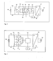
- Fig. 1 a basic circuit of the solar module according to the invention is shown as a first embodiment in a simplified form.
- Fig. 5 shown conventional circuit arrangement.
- the solar module of Fig. 1 includes a solar generator 10 for converting incident light into electrical power and a solar inverter 12 for feeding the power generated by the solar generator 10 in a network 14 or a consumer. As in Fig. 1 illustrated, the solar generator 10 is connected to a DC link with a DC link capacitor 16.
- the solar generator 10 and the intermediate circuit 16 is connected to a DC / DC converter 22.
- This DC / DC converter 22 converts the variable voltage generated by the solar generator 10 and smoothed by the intermediate circuit 16 into a substantially constant low voltage. With this constant low voltage then the control electronics of the solar module can be powered by the solar generator side. That the control electronics of the solar module does not have to be powered by the network 14 and the solar module can thus feed power into the network 14 even with very low or no mains voltage.
- the solar module is provided with a variable preload 18, which is connected to the output of the DC / DC converter 22 and is controlled by the microcontroller 20.
- the pre-load 18 shown is shown from a combination of sub-elements, with a current sink 30, a switchable 26 consumers and a controllable load 28.
- the preload 18 may also be formed by a different combination of sub-elements or by a single sub-element, for example by a current sink 30 in the form of a transistor which can be switched on and off by means of a transistor.
- variable preload 18 Due to the connection of the variable preload 18 to the DC / DC converter 22, this does not have to adapt to the variable voltage of the solar generator 10. Instead, the DC / DC converter 22 converts this variable voltage of the solar generator 10 into a constant low voltage, for which a constant power consumption by the variable preload 18 is much easier to achieve.
- variable preload 18 can be reduced in their power capacity by the losses occurring in the DC / DC converter 22. Significant savings in space and cost for the variable preload 18 result from the above points.
- the microcontroller 20 serves to control the variable preload 18 or the sub-elements contained therein.
- the control of the inverter 12 and its idling operation as additional load for the solar generator 10 can be made via the same microcontroller 20.
- the solar generator 10 Before connecting the solar inverter 12 to the network 14, the solar generator 10 is loaded by means of the variable preload 18.
- the load is set by the microcontroller 20 so that the currently available power of the solar generator 10 can be measured at an optimal operating point.
- the microcontroller 20 calculates the no-load losses of the solar inverter 12, which would arise at the moment when the grid is connected. These no-load losses are mainly dependent on the mains voltage and the solar generator voltage, and their course depends strongly on the topology of the solar inverter 12.
- the microcontroller 20 switches the solar inverter 12 to the grid 14 or the load. Since the solar generator 10 is already at the optimum operating point, a seamless transition to the feed-in operation without energy losses is possible.
- connection conditions for the solar inverter 12 can be used. For example, sufficient generator power must be available for a given minimum amount of time.
- the operating point in which the power of the solar generator 10 is measured may be the MPP (maximum power point) of the solar generator 10. However, more preferably, it is measured at an operating point that represents the MPP for the entire solar module. This is possible without the solar module being in feed mode, since its losses and its dependence on mains voltage and generator voltage are known.
- the operating point can be selected either fixed or depending on various parameters (for example mains voltage). It can also be optimized via tracking and self-learning features.
- the current sink 30 of the solar module may optionally be linear, i. with analog adjustable load, or clocked, i. with over the on / off ratio adjustable load, are executed.
- variable preload 18 For the operation of the variable preload 18 no additional measuring devices in the solar module are necessary, since the voltages on the generator side 10 and the intermediate circuit 16 and the net side 14 must be measured anyway. If the total power of the preload 18 and the efficiency of the DC / DC converter 22 1 , 22 2 , 22 3 and possibly the losses of open-ended as additional load power electronics are known, can also be dispensed with the measurement of the solar generator current.
- the storage capacitor 16 of the intermediate circuit can also be discharged via the variable preload 18 of the solar module.
- the storage capacitor 16 is usually very large and can be charged, for example, to over 800 V.
- the variable preload 18 can be used to eliminate this charge of the storage capacitor 16 in a short time, which is advantageous for example during manufacturing and service.
- Of the Storage capacitor 16 is discharged via the preload 18 by a corresponding control by the microcontroller 20 for this purpose.
- variable preload 18 In order to use the variable preload 18 for discharging the storage capacitor 16 of the intermediate circuit, it is advantageous to configure the DC / DC converter 22 so that it operates down to very low voltages. Thus, the DC link can be discharged to a harmless residual charge. It is quite sufficient if the DC / DC converter 22 can deliver only a part of its nominal power at low input voltages. In order that the output voltage of the DC / DC converter 22 then does not collapse, the variable preload 18 can be reduced in its power or switched off when the microcontroller 20 falls below a minimum voltage.
- a display device (not shown) may be provided, with which the state of charge of the storage capacitor 16 of the intermediate circuit can be optically displayed. This happens, for example, in a power-saving and at the same time clearly visible way by a periodically flashing LED whose flash frequency is proportional to the charge in the DC link.
- a display device for indicating a discharge current of the storage capacitor 16 of the intermediate circuit can be provided by the variable preload 18.
- variable preload 18 is in addition to the above-mentioned EP 1 970 964 A2 Reference is made, the content of which is hereby also to be made the subject of this application.
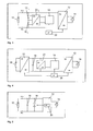
- the intermediate circuit is often designed as a series circuit of a plurality of electrolytic capacitors 16 1 , 16 2 , as in Fig. 2 shown.
- each of the storage capacitors 16 1 , 16 2 of the intermediate circuit is associated with a DC / DC converter 22 1 , 22 2 (with a single input).
- variable preload 18 is preferably connected to the common output of the two DC / DC converters 22 1 , 22 2 .
- the variable preload 18 of this and the following embodiments is shown in simplified form. The variants explained in the previous embodiment are also valid.
- the DC / DC converters 22 1 , 22 2 can also be used to balance the storage capacitors 16 1 , 16 2 of the intermediate circuit.
- the DC / DC converters 22 1 , 22 2 for example, regulated so that the higher-charged DC link capacitors 16 1 , 16 2 are more discharged.
- variable preload 18 are connected to the common output of the DC / DC converter 22 1 , 22 2 , it is also possible to connect to the separate outputs of the DC / DC converter 22 1 , 22 2 each have a variable preload 18.
- a third embodiment of a solar module will be explained in more detail.
- the same or corresponding components are again identified by the same reference numerals, and below only the differences from the second embodiment of Fig. 2 described.
- FIG. 3 shown solar module differs from the solar module of the second embodiment of Fig. 2 in that the several series-connected storage capacitors 16 1 , 16 2 of the intermediate circuit are coupled to only one DC / DC converter 22 3 with a multiple input.
- a fourth embodiment of a solar module will be explained in more detail.
- the same or corresponding components are identified by the same reference numerals, and only the differences from the first embodiment of Fig. 1 described.
- a solar generator 10 is connected via a DC / DC converter 32, for example a step-up converter, to a DC link.
- the DC / DC converter 32 makes it possible to adapt the voltage generated by the solar generator 10 to the mains voltage.
- the illustrated embodiments may have at least one inductor in the intermediate circuit instead of at least one intermediate circuit capacitor 16.
- the second and the third embodiment can also be combined with each other, if the intermediate circuit comprises more than two storage capacitors.
- the solar module can have multiple DC / DC converters 22 1 , 22 2 with a single input, multiple DC / DC converters 22 3 having a multiple input or at least one DC / DC converter 22 1 , 22 2 having a single input and at least one DC / DC converter 22 3 having a multiple input.
- the fourth embodiment can be combined with the second or the third embodiment.
Landscapes
- Engineering & Computer Science (AREA)
- Power Engineering (AREA)
- Charge And Discharge Circuits For Batteries Or The Like (AREA)
- Photovoltaic Devices (AREA)
Applications Claiming Priority (1)
| Application Number | Priority Date | Filing Date | Title |
|---|---|---|---|
| DE102010055486A DE102010055486A1 (de) | 2010-12-22 | 2010-12-22 | Solarmodul und Verfahren |
Publications (1)
| Publication Number | Publication Date |
|---|---|
| EP2469601A2 true EP2469601A2 (fr) | 2012-06-27 |
Family
ID=45421764
Family Applications (1)
| Application Number | Title | Priority Date | Filing Date |
|---|---|---|---|
| EP11009807A Withdrawn EP2469601A2 (fr) | 2010-12-22 | 2011-12-14 | Module solaire et procédé |
Country Status (2)
| Country | Link |
|---|---|
| EP (1) | EP2469601A2 (fr) |
| DE (1) | DE102010055486A1 (fr) |
Cited By (1)
| Publication number | Priority date | Publication date | Assignee | Title |
|---|---|---|---|---|
| CN114128115A (zh) * | 2020-06-30 | 2022-03-01 | 华为数字能源技术有限公司 | 一种逆变器、逆变系统及方法 |
Families Citing this family (2)
| Publication number | Priority date | Publication date | Assignee | Title |
|---|---|---|---|---|
| DE102014007639A1 (de) * | 2014-05-22 | 2015-11-26 | AMK Arnold Müller GmbH & Co. KG | System zur Einspeisung elektrischer Energie in ein Stromversorgungsnetz |
| DE102014007640A1 (de) * | 2014-05-22 | 2015-11-26 | AMK Arnold Müller GmbH & Co. KG | System zur Einspeisung elektrischer Energie in ein Stromversorgungsnetz und Betriebsverfahren für ein solches System |
Family Cites Families (5)
| Publication number | Priority date | Publication date | Assignee | Title |
|---|---|---|---|---|
| DE4328511C2 (de) * | 1993-08-25 | 1995-06-22 | Zsw | Einschaltsteuerungsverfahren und -steuerschaltung für einen einen Solargenerator an das Stromnetz ankoppelnden Wechselrichter |
| DE102007012590B3 (de) | 2007-03-13 | 2008-11-27 | Diehl Ako Stiftung & Co. Kg | Solarmodul |
| DE102008059428A1 (de) | 2008-11-27 | 2010-06-10 | Diehl Ako Stiftung & Co. Kg | Energieeinspeisevorrichtung |
| CN101534061B (zh) | 2009-04-09 | 2011-09-07 | 福州大学 | 双隔离升压型多输入直流变换器 |
| CN101534058B (zh) | 2009-04-09 | 2011-04-06 | 福州大学 | 双隔离降压型多输入直流变换器 |
-
2010
- 2010-12-22 DE DE102010055486A patent/DE102010055486A1/de not_active Withdrawn
-
2011
- 2011-12-14 EP EP11009807A patent/EP2469601A2/fr not_active Withdrawn
Cited By (2)
| Publication number | Priority date | Publication date | Assignee | Title |
|---|---|---|---|---|
| CN114128115A (zh) * | 2020-06-30 | 2022-03-01 | 华为数字能源技术有限公司 | 一种逆变器、逆变系统及方法 |
| EP4156483A4 (fr) * | 2020-06-30 | 2023-07-05 | Huawei Digital Power Technologies Co., Ltd. | Onduleur, et système et procédé d'ondulation |
Also Published As
| Publication number | Publication date |
|---|---|
| DE102010055486A1 (de) | 2012-06-28 |
Similar Documents
| Publication | Publication Date | Title |
|---|---|---|
| EP1851846B1 (fr) | Onduleur | |
| EP2363947B1 (fr) | Onduleur doté d'un réseau de bord alimenté de plusieurs manières | |
| EP2962380B1 (fr) | Agencement de circuit d'alimentation de tension en ligne, utilisation d'un tel agencement de circuit et dispositif équipé d'un tel agencement de circuit | |
| EP1914857B1 (fr) | Dispositif de circuit électrique et procédé, en particulier pour des générateurs photovoltaic | |
| DE102008004675B3 (de) | Steuerbare Umschaltvorrichtung für ein Solarmodul | |
| EP3022835B1 (fr) | Onduleur comprenant au moins deux entrées de courant continu, installation photovoltaïque comprenant un tel onduleur et procédé de commande d'un onduleur | |
| EP2365599B1 (fr) | Dispositif de conversion d'énergie électrique et procédé de fonctionnement d'un tel dispositif | |
| WO2006000263A1 (fr) | Dispositif et procede d'egalisation de la charge d'accumulateurs d'energie commutes en serie | |
| WO2006100264A2 (fr) | Dispositif et procede pour l'equilibrage de charge de cellules individuelles disposees en rangee d'un accumulateur d'energie | |
| DE102007012590B3 (de) | Solarmodul | |
| EP3465896A1 (fr) | Dispositif de conversion de tension continue équipé d'une cascade faite d'un convertisseur de résonance isolé et d'un convertisseur élévateur/abaisseur | |
| EP2173024A2 (fr) | Agencement de commutation doté d'un transformateur élévateur de tension et commutateur doté d'un tel agencement de commutation | |
| EP2158671A1 (fr) | Unité de redresseur sans transformateur pour panneaux solaires en film mince | |
| DE112013006090T5 (de) | Leistungsübertragungssystem | |
| EP2228893A2 (fr) | Installation photovoltaïque avec un dispositif de chargement pour la capacité d'entrée du onduleur | |
| DE102011087015A1 (de) | Energieversorgungssystem, Luft- oder Raumfahrzeug und Verfahren | |
| DE102011115189A1 (de) | PV-Anlage mit Sicherung gegen Einspeisung in ein öffentliches Stromversorgungsnetz | |
| EP2469601A2 (fr) | Module solaire et procédé | |
| DE102013201909B4 (de) | Energiespeichereinrichtung und Verfahren zum Ansteuern einer Energiespeichereinrichtung bei einem Kommunikationsausfall | |
| DE102014016076A1 (de) | DC/DC-Wandler für ein Kraftfahrzeug | |
| EP3297115A1 (fr) | Système comprenant un dispositif d'accumulation d'énergie et un convertisseur d'énergie destiné à recevoir de l'énergie électrique provenant d'un réseau électrique et fournir l'énergie électrique au réseau électrique | |
| EP3361596B1 (fr) | Batterie avec un système de gestion de batterie comprenant un dispositif interrupteur | |
| WO2007036374A2 (fr) | Onduleur pour deux sources de courant continu et procede pour le faire fonctionner | |
| EP3117511A1 (fr) | Procédé d'identification de l'effondrement d'une tension | |
| DE102007016039A1 (de) | Vorrichtung und Verfahren zur Ansteuerung einer induktiven Last |
Legal Events
| Date | Code | Title | Description |
|---|---|---|---|
| AK | Designated contracting states |
Kind code of ref document: A2 Designated state(s): AL AT BE BG CH CY CZ DE DK EE ES FI FR GB GR HR HU IE IS IT LI LT LU LV MC MK MT NL NO PL PT RO RS SE SI SK SM TR |
|
| AX | Request for extension of the european patent |
Extension state: BA ME |
|
| PUAI | Public reference made under article 153(3) epc to a published international application that has entered the european phase |
Free format text: ORIGINAL CODE: 0009012 |
|
| RAP1 | Party data changed (applicant data changed or rights of an application transferred) |
Owner name: PLATINUM GMBH |
|
| 19U | Interruption of proceedings before grant |
Effective date: 20140601 |
|
| 19W | Proceedings resumed before grant after interruption of proceedings |
Effective date: 20170403 |
|
| STAA | Information on the status of an ep patent application or granted ep patent |
Free format text: STATUS: THE APPLICATION IS DEEMED TO BE WITHDRAWN |
|
| 18D | Application deemed to be withdrawn |
Effective date: 20171003 |