EP2193320B1 - Appareil réfrigérant - Google Patents
Appareil réfrigérant Download PDFInfo
- Publication number
- EP2193320B1 EP2193320B1 EP08803277.6A EP08803277A EP2193320B1 EP 2193320 B1 EP2193320 B1 EP 2193320B1 EP 08803277 A EP08803277 A EP 08803277A EP 2193320 B1 EP2193320 B1 EP 2193320B1
- Authority
- EP
- European Patent Office
- Prior art keywords
- storage container
- cooling device
- disposed
- gear
- pinion gear
- Prior art date
- Legal status (The legal status is an assumption and is not a legal conclusion. Google has not performed a legal analysis and makes no representation as to the accuracy of the status listed.)
- Active
Links
Images

Classifications
-
- F—MECHANICAL ENGINEERING; LIGHTING; HEATING; WEAPONS; BLASTING
- F25—REFRIGERATION OR COOLING; COMBINED HEATING AND REFRIGERATION SYSTEMS; HEAT PUMP SYSTEMS; MANUFACTURE OR STORAGE OF ICE; LIQUEFACTION SOLIDIFICATION OF GASES
- F25D—REFRIGERATORS; COLD ROOMS; ICE-BOXES; COOLING OR FREEZING APPARATUS NOT OTHERWISE PROVIDED FOR
- F25D23/00—General constructional features
- F25D23/02—Doors; Covers
- F25D23/04—Doors; Covers with special compartments, e.g. butter conditioners
-
- F—MECHANICAL ENGINEERING; LIGHTING; HEATING; WEAPONS; BLASTING
- F25—REFRIGERATION OR COOLING; COMBINED HEATING AND REFRIGERATION SYSTEMS; HEAT PUMP SYSTEMS; MANUFACTURE OR STORAGE OF ICE; LIQUEFACTION SOLIDIFICATION OF GASES
- F25D—REFRIGERATORS; COLD ROOMS; ICE-BOXES; COOLING OR FREEZING APPARATUS NOT OTHERWISE PROVIDED FOR
- F25D25/00—Charging, supporting, and discharging the articles to be cooled
- F25D25/02—Charging, supporting, and discharging the articles to be cooled by shelves
- F25D25/024—Slidable shelves
- F25D25/025—Drawers
-
- A—HUMAN NECESSITIES
- A47—FURNITURE; DOMESTIC ARTICLES OR APPLIANCES; COFFEE MILLS; SPICE MILLS; SUCTION CLEANERS IN GENERAL
- A47B—TABLES; DESKS; OFFICE FURNITURE; CABINETS; DRAWERS; GENERAL DETAILS OF FURNITURE
- A47B2210/00—General construction of drawers, guides and guide devices
- A47B2210/17—Drawers used in connection with household appliances
Definitions
- the present invention relates to a cooling device comprising a storage container that opens by rotating.
- cooling devices In cooling devices, storage containers are used whereon objects to be cooled are placed, that can be pulled out of the cooling cabin partially or entirely like a drawer particularly by the user for loading or unloading. These storage containers can be positioned at various levels inside the cabin.
- storage containers are developed that can open by turning sideways or to the front in order to access easily into the storage containers for activities of unloading and cleaning.
- the storage containers that open by tilting forward provide convenience of usage.
- Various embodiments are developed in the state of the art relating to the movement and assembly of storage containers that open by tilting forward.
- the drawer moves on two pins, one on the side wall and the other on the base of the space containing thereof. While the shaft moves horizontally in a housing formed on the side wall of the section wherein the drawer is disposed, the base of the drawer slides on the pin on the base of the section.
- the base of the drawer is shaped for opening by tilting. As the base thereof moves on the pin, it moves according to the formed shape.
- the shape of the base is configured to be uneven with partial planes instead of a single arc segment in order to turn the drawer controllably.
- the drawer slows down while passing from the flat planes and forward movement is controlled.
- the aim of the present invention is realization of a cooling device comprising a storage container that opens controllably by tilting forward.
- the cooling device realized in order to attain the aim of the present invention, explicated in the first claim and the respective claims thereof, comprises a storage container disposed on the door or the cooling cabin that opens by tilting forward and a pinion gear- gearwheel pair that provides the opening motion of the storage container to be controlled.
- the cooling device comprises at least one chamber wherein the storage container is disposed, a bearing mechanism for securing thereof, allowing to rotate for opening by tilting forward and a locking mechanism that locks the storage container in that position when brought to the closed position.
- the gear path is disposed on the outer wall of the storage container and the pinion gear on the inner wall of the chamber so that the teeth thereof are engaged with the gear path.
- the pinion gear is disposed on the chamber inner wall rotatable around its own axis.
- the gear path situated on the outer wall of the storage container, moves forward together with the storage container while it is opening. The motion of the gear path provides the pinion gear to rotate and the friction during this motion maintains the storage container to be opened controllably and softly. Accordingly, the storage container, when full, is prevented from opening rapidly with its weight and therefore damaging the items placed therein.
- the bearing mechanism comprises at least one shaft on the storage container and at least one housing at the lower side of the chamber, wherein this shaft can be received.
- the storage container tilts by the shaft rotating around its axis in the housing.
- the pinion gear comprises a coil spring that is wound by the motion of the storage container while closing, storing energy and spends this stored energy by rotating the storage container while opening.
- the coil spring is disposed in the center such that the pinion is triggered to rotate.
- the user pushes the storage container for closing the storage container. While the storage container moves towards the closed position by the exerted force, the gear path also moves forward rotating the pinion gear. Meanwhile the coil spring at the center of the pinion gear is wound. When the storage container is in the entirely closed position, the pinion gear is situated at the end of the gearwheel and the coil spring is wound. In this position, the locking mechanism changes to the locked position and keeps the storage container in the closed position.
- the pinion gear comprises a coil spring that is wound by the motion of the storage container while opening and thereby storing energy and spends this stored energy while the storage container is closing and provides the storage container to move by itself in the closing direction.
- the coil spring is disposed in the center such that the pinion gear is triggered to rotate. Consequently, not only the storage container is further slowed in falling in the opening direction by its own weight but also the closing process is performed softly.
- the locking mechanism is a push-in-pop-out type of mechanism.
- the locking mechanism comprises a heart shaped support and a resilient pin that moves around this support for unlocking and unlocking.
- locking is performed as the user closes the storage container.
- the lock opens by slightly pushing the storage container in the closed position forwards and the storage container is enabled to easily start moving for changing to the open position.
- the storage container and the chamber containing the storage container can be placed under the shelves situated on the door or the cabin or directly on a channel formed on the door or the cabin.
- the storage container used in the cooling device of the present invention moves controllably while opening by tilting forward and thus a convenient and safe usage is provided.
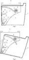
- the cooling device (1) comprises a cabin (2), at least one door (3) for accessing inside the cabin (2), at least one storage container (4) disposed on the cabin (2) or the door (3), wherein items to be cooled are stored, at least one chamber (5) wherein the storage container (4) is disposed, a bearing mechanism (9) for securing the storage container (4) to the chamber (5) allowing rotation for opening by tilting forward and a locking mechanism (12) for locking the storage container (4) in that position when the storage container (4) is changed to the closed position ( Figure 1 and Figure 2 ).
- the cooling device (1) furthermore comprises at least one gear path (7) disposed on the outer wall of the storage container (4) and a pinion gear (6) disposed on the inner wall of the chamber (5), aligned with the gear path (7), attached to rotate around its axis and rotated by the motion of the gear path (7) while the storage container (4) is opening.
- the gear path (7) is configured as a gear piece having a step size matching the steps of the pinion gear (6). While the storage container (4) is opening, the gear path (7) moves together with the storage container (4) and the pinion gear (6) rotates as a result of this motion and prevents the storage container (4) to suddenly fall by its own weight.
- the bearing mechanism (9) comprises a shaft (10) disposed on the rear lower corners of the storage container (4) and a housing (11) situated on the chamber (5), wherein the shaft (10) is placed such that the storage container (4) is allowed to tilt forward by rotating.
- the storage container (4) tilts by rotating around the axis of the shaft (10).
- the pinion gear (6) comprises a coil spring (8) disposed at the core.
- the coil spring (8) is wound by the motion of the storage container (4) while closing to store energy and spends this stored energy by helping the pinion gear (6) to rotate with the movement of the gear path (7).
- the pinion gear (6) and the gear path (7) are prevented from getting stuck due to friction and the movement to be entirely inhibited ( Figures 2 and 3 ).
- the storage container (4) is pushed for changing to the closed position. While the storage container (4) moves towards the closed position by the exerted force, the pinion gear (6) rotates as well and the coil spring (8) at the core of the pinion gear (6) is wound. When the storage container (4) is in the entirely closed position, the pinion gear (6) reaches the end of the gear path (7) and the coil spring (8) is entirely wound as well and also the locking mechanism (12) changes to the locked position and keeps the storage container (4) in the closed position.
- the ratio of diameters of the pinion gear (6) and the gear path (7) is in the range of 1/12 to 1/17.
- the pinion gear (6) comprises a coil spring (8) that is wound by the motion of the storage container (4) while opening and stores energy.
- the coil spring (8) spends the stored energy while the storage container (4) is closing and helps the storage container (4) to move in the closing direction.
- the falling down of the storage container (4) by its weight in the opening direction is slowed down and the closing process is performed softly.
- the locking mechanism (12) is a push-in-pop-out type of mechanism and it is sufficient to push a little and then to release in order to set free the storage container (4) in the closed position.
- the locking mechanism (12) comprises a heart shaped support (13) disposed on the side wall of the storage container (4) and a resilient pin (14) disposed on the side wall of the chamber (5) that moves around this support (13) for locking and unlocking.
- the storage container (4) can be disposed under one of the shelves (R) situated on the door (4) or the cabin (2).
- the storage container (4) that opens by tilting forward is prevented from opening uncontrollably and the damaging of the items placed therein, the storage container (4) is enabled to change to the open position by moving softly and controllably.
Landscapes
- Engineering & Computer Science (AREA)
- Chemical & Material Sciences (AREA)
- Combustion & Propulsion (AREA)
- Physics & Mathematics (AREA)
- Mechanical Engineering (AREA)
- Thermal Sciences (AREA)
- General Engineering & Computer Science (AREA)
- Passenger Equipment (AREA)
- Vehicle Step Arrangements And Article Storage (AREA)
Claims (9)
- Un dispositif de refroidissement (1) qui comprend- une cabine (2)- au moins une porte (3) pour accéder à l'intérieur de la cabine (2),- au moins un récipient de stockage (4) disposé sur la cabine (2) ou la porte (3), dans lequel les éléments à refroidir sont stockés,- au moins une chambre (5) dans laquelle le récipient de stockage (4) est disposé,- un mécanisme de palier (9) pour fixer le récipient de stockage (4) à la chambre (5) permettant la rotation pour l'ouverture en inclinant vers l'avant,- un mécanisme de verrouillage (12) pour verrouiller le récipient de stockage (4) dans cette position lorsque le récipient de stockage (4) est changé en position fermée et- au moins une voie d'engrenage (7) disposée sur la paroi extérieure du récipient de stockage (4) et un engrenage à pignon (6) disposé sur la paroi intérieure de la chambre (5) aligné avec la voie d'engrenage (7), fixé à tourner autour de son axe et tourné par le mouvement de la voie d'engrenage (7) pendant l'ouverture du réservoir de stockage (4), caractérisé en ce que le mécanisme de palier (9) comprend un arbre (10) disposé sur le récipient de stockage (4) tel que le récipient de stockage (4) tourne autour de l'axe dudit arbre (10) et un boîtier (11) situé sur la chambre (5), dans lequel l'arbre (10) est placé de sorte que le récipient de stockage (4) est autorisé pour incliner vers l'avant en tournant.
- Un dispositif de refroidissement (1) selon la revendication 1, caractérisé par la voie d'engrenage (7) ayant la taille de pas correspondant aux pas de l'engrenage à pignons (6).
- Un dispositif de refroidissement (1) selon les revendications 1 ou 2, caractérisé par l'engrenage à pignon (6) et la voie d'engrenage (7) avec le rapport de leurs diamètres étant dans la plage de 1/12 à 1/17.
- Un dispositif de refroidissement (1) selon l'une quelconque des revendications précédentes, caractérisé par l'engrenage à pignon (6) comprenant un ressort hélicoïdal (8) qui est enroulé par le mouvement du récipient de stockage (4) tout en fermant pour stocker de l'énergie et dépense cette énergie stockée tandis que le conteneur de stockage (4) s'ouvre pour aider à la faire tourner par le mouvement de la voie d'engrenage (7).
- Un dispositif de refroidissement (1) selon l'une quelconque des revendications 1 à 3, caractérisé par l'engrenage à pignon (6) comprenant un ressort hélicoïdal (8) qui est enroulé par le mouvement du récipient de stockage (4) tout en ouvrant pour stocker de l'énergie et dépense cette énergie stockée tandis que le conteneur de stockage (4) se ferme et permet de la faire tourner par le mouvement de la voie d'engrenage (7) et maintient la fermeture douce.
- Un dispositif de refroidissement (1) selon l'une quelconque des revendications précédentes, caractérisé par un mécanisme de verrouillage (12) de type push-in pop-out.
- Un dispositif de refroidissement (1) selon la revendication 6, caractérisé par le mécanisme de verrouillage (12) comprenant un support en forme de coeur (13) disposé sur la paroi latérale du récipient de stockage (4) et une épingle (14) disposée sur la paroi latérale de la chambre (5) qui se déplace autour de ce support (13) pour le verrouillage et le déverrouillage.
- Un dispositif de refroidissement (1) selon l'une quelconque des revendications précédentes, caractérisé en ce que le récipient de stockage (4) est disposé sous une étagère (R) située sur la porte (3).
- Un dispositif de refroidissement (1) selon l'une quelconque des revendications précédentes, caractérisé en ce que le récipient de stockage (4) est disposé sous une étagère (R) située sur la cabine (2).
Applications Claiming Priority (2)
| Application Number | Priority Date | Filing Date | Title |
|---|---|---|---|
| TR200706044 | 2007-08-31 | ||
| PCT/EP2008/061251 WO2009027443A2 (fr) | 2007-08-31 | 2008-08-27 | Appareil réfrigérant |
Publications (2)
| Publication Number | Publication Date |
|---|---|
| EP2193320A2 EP2193320A2 (fr) | 2010-06-09 |
| EP2193320B1 true EP2193320B1 (fr) | 2017-08-02 |
Family
ID=40387923
Family Applications (1)
| Application Number | Title | Priority Date | Filing Date |
|---|---|---|---|
| EP08803277.6A Active EP2193320B1 (fr) | 2007-08-31 | 2008-08-27 | Appareil réfrigérant |
Country Status (2)
| Country | Link |
|---|---|
| EP (1) | EP2193320B1 (fr) |
| WO (1) | WO2009027443A2 (fr) |
Cited By (1)
| Publication number | Priority date | Publication date | Assignee | Title |
|---|---|---|---|---|
| EP4130625A4 (fr) * | 2020-03-30 | 2023-08-23 | Qingdao Haier Refrigerator Co., Ltd | Boîte de stockage et réfrigérateur le comprenant |
Families Citing this family (2)
| Publication number | Priority date | Publication date | Assignee | Title |
|---|---|---|---|---|
| EP3205958B1 (fr) | 2010-02-01 | 2019-11-13 | LG Electronics Inc. | Réfrigérateur |
| DE102011006235A1 (de) * | 2011-03-28 | 2012-10-04 | BSH Bosch und Siemens Hausgeräte GmbH | Kühlgutablage und Kältegerät |
Family Cites Families (5)
| Publication number | Priority date | Publication date | Assignee | Title |
|---|---|---|---|---|
| JPS6178980A (ja) * | 1984-09-26 | 1986-04-22 | 株式会社 ニフコ | 引出体の引出し装置 |
| DE29519963U1 (de) * | 1995-12-16 | 1997-04-10 | AEG Hausgeräte GmbH, 90429 Nürnberg | Kühl- und/oder Gefriergerät |
| DE20016348U1 (de) * | 2000-09-21 | 2001-01-11 | Brunnert, Eberhard, Dipl.-Ing. (FH), 89231 Neu-Ulm | Kippschwenk-Lade |
| KR100953977B1 (ko) * | 2003-10-04 | 2010-04-21 | 엘지전자 주식회사 | 냉장고용 도어바스켓 |
| US7472974B2 (en) * | 2005-05-06 | 2009-01-06 | Whirlpool Corporation | Refrigerator with storage bin |
-
2008
- 2008-08-27 WO PCT/EP2008/061251 patent/WO2009027443A2/fr not_active Ceased
- 2008-08-27 EP EP08803277.6A patent/EP2193320B1/fr active Active
Non-Patent Citations (1)
| Title |
|---|
| None * |
Cited By (1)
| Publication number | Priority date | Publication date | Assignee | Title |
|---|---|---|---|---|
| EP4130625A4 (fr) * | 2020-03-30 | 2023-08-23 | Qingdao Haier Refrigerator Co., Ltd | Boîte de stockage et réfrigérateur le comprenant |
Also Published As
| Publication number | Publication date |
|---|---|
| EP2193320A2 (fr) | 2010-06-09 |
| WO2009027443A2 (fr) | 2009-03-05 |
| WO2009027443A3 (fr) | 2009-06-25 |
Similar Documents
| Publication | Publication Date | Title |
|---|---|---|
| US11105552B2 (en) | Refrigerator | |
| EP3674640B1 (fr) | Réfrigérateur | |
| EP3207319B1 (fr) | Réfrigérateur | |
| EP3653979B1 (fr) | Réfrigérateur | |
| CN201340153Y (zh) | 冰箱 | |
| EP2193320B1 (fr) | Appareil réfrigérant | |
| EP3677860B1 (fr) | Réfrigérateur | |
| WO2003091643A1 (fr) | Element de rayonnage et refrigerateur pourvu dudit element | |
| KR101861368B1 (ko) | 냉장고 | |
| KR100861347B1 (ko) | 냉장고의 서랍식 도어 개폐장치 | |
| JP5312399B2 (ja) | 冷蔵庫 | |
| CN213273351U (zh) | 具有翻转梁的冰箱 | |
| KR20060050539A (ko) | 냉장고 | |
| KR102227959B1 (ko) | 냉장고 | |
| EP4130625B1 (fr) | Boîte de stockage et réfrigérateur le comprenant | |
| EP2321484B1 (fr) | Appareil ménager | |
| CN109708416A (zh) | 抽屉组件 | |
| JP5595086B2 (ja) | キャビネット | |
| KR101654933B1 (ko) | 냉장고의 수납장치 | |
| KR101248297B1 (ko) | 홈바 도어의 개폐장치 | |
| JP4426422B2 (ja) | ドアガード | |
| JPH112483A (ja) | 冷蔵庫の収納装置 | |
| EP4685420A1 (fr) | Réfrigérateur | |
| KR100728381B1 (ko) | 냉장고용 홈바 | |
| US20240200851A1 (en) | Door storage assembly |
Legal Events
| Date | Code | Title | Description |
|---|---|---|---|
| PUAI | Public reference made under article 153(3) epc to a published international application that has entered the european phase |
Free format text: ORIGINAL CODE: 0009012 |
|
| 17P | Request for examination filed |
Effective date: 20100316 |
|
| AK | Designated contracting states |
Kind code of ref document: A2 Designated state(s): AT BE BG CH CY CZ DE DK EE ES FI FR GB GR HR HU IE IS IT LI LT LU LV MC MT NL NO PL PT RO SE SI SK TR |
|
| AX | Request for extension of the european patent |
Extension state: AL BA MK RS |
|
| DAX | Request for extension of the european patent (deleted) | ||
| GRAP | Despatch of communication of intention to grant a patent |
Free format text: ORIGINAL CODE: EPIDOSNIGR1 |
|
| INTG | Intention to grant announced |
Effective date: 20170410 |
|
| GRAS | Grant fee paid |
Free format text: ORIGINAL CODE: EPIDOSNIGR3 |
|
| GRAA | (expected) grant |
Free format text: ORIGINAL CODE: 0009210 |
|
| AK | Designated contracting states |
Kind code of ref document: B1 Designated state(s): AT BE BG CH CY CZ DE DK EE ES FI FR GB GR HR HU IE IS IT LI LT LU LV MC MT NL NO PL PT RO SE SI SK TR |
|
| REG | Reference to a national code |
Ref country code: GB Ref legal event code: FG4D |
|
| REG | Reference to a national code |
Ref country code: CH Ref legal event code: EP Ref country code: AT Ref legal event code: REF Ref document number: 914929 Country of ref document: AT Kind code of ref document: T Effective date: 20170815 |
|
| REG | Reference to a national code |
Ref country code: IE Ref legal event code: FG4D |
|
| REG | Reference to a national code |
Ref country code: DE Ref legal event code: R096 Ref document number: 602008051416 Country of ref document: DE |
|
| REG | Reference to a national code |
Ref country code: NL Ref legal event code: MP Effective date: 20170802 |
|
| REG | Reference to a national code |
Ref country code: AT Ref legal event code: MK05 Ref document number: 914929 Country of ref document: AT Kind code of ref document: T Effective date: 20170802 |
|
| REG | Reference to a national code |
Ref country code: LT Ref legal event code: MG4D |
|
| PG25 | Lapsed in a contracting state [announced via postgrant information from national office to epo] |
Ref country code: NO Free format text: LAPSE BECAUSE OF FAILURE TO SUBMIT A TRANSLATION OF THE DESCRIPTION OR TO PAY THE FEE WITHIN THE PRESCRIBED TIME-LIMIT Effective date: 20171102 Ref country code: SE Free format text: LAPSE BECAUSE OF FAILURE TO SUBMIT A TRANSLATION OF THE DESCRIPTION OR TO PAY THE FEE WITHIN THE PRESCRIBED TIME-LIMIT Effective date: 20170802 Ref country code: HR Free format text: LAPSE BECAUSE OF FAILURE TO SUBMIT A TRANSLATION OF THE DESCRIPTION OR TO PAY THE FEE WITHIN THE PRESCRIBED TIME-LIMIT Effective date: 20170802 Ref country code: LT Free format text: LAPSE BECAUSE OF FAILURE TO SUBMIT A TRANSLATION OF THE DESCRIPTION OR TO PAY THE FEE WITHIN THE PRESCRIBED TIME-LIMIT Effective date: 20170802 Ref country code: AT Free format text: LAPSE BECAUSE OF FAILURE TO SUBMIT A TRANSLATION OF THE DESCRIPTION OR TO PAY THE FEE WITHIN THE PRESCRIBED TIME-LIMIT Effective date: 20170802 Ref country code: FI Free format text: LAPSE BECAUSE OF FAILURE TO SUBMIT A TRANSLATION OF THE DESCRIPTION OR TO PAY THE FEE WITHIN THE PRESCRIBED TIME-LIMIT Effective date: 20170802 Ref country code: NL Free format text: LAPSE BECAUSE OF FAILURE TO SUBMIT A TRANSLATION OF THE DESCRIPTION OR TO PAY THE FEE WITHIN THE PRESCRIBED TIME-LIMIT Effective date: 20170802 |
|
| PG25 | Lapsed in a contracting state [announced via postgrant information from national office to epo] |
Ref country code: GR Free format text: LAPSE BECAUSE OF FAILURE TO SUBMIT A TRANSLATION OF THE DESCRIPTION OR TO PAY THE FEE WITHIN THE PRESCRIBED TIME-LIMIT Effective date: 20171103 Ref country code: ES Free format text: LAPSE BECAUSE OF FAILURE TO SUBMIT A TRANSLATION OF THE DESCRIPTION OR TO PAY THE FEE WITHIN THE PRESCRIBED TIME-LIMIT Effective date: 20170802 Ref country code: IS Free format text: LAPSE BECAUSE OF FAILURE TO SUBMIT A TRANSLATION OF THE DESCRIPTION OR TO PAY THE FEE WITHIN THE PRESCRIBED TIME-LIMIT Effective date: 20171202 Ref country code: BG Free format text: LAPSE BECAUSE OF FAILURE TO SUBMIT A TRANSLATION OF THE DESCRIPTION OR TO PAY THE FEE WITHIN THE PRESCRIBED TIME-LIMIT Effective date: 20171102 Ref country code: LV Free format text: LAPSE BECAUSE OF FAILURE TO SUBMIT A TRANSLATION OF THE DESCRIPTION OR TO PAY THE FEE WITHIN THE PRESCRIBED TIME-LIMIT Effective date: 20170802 Ref country code: PL Free format text: LAPSE BECAUSE OF FAILURE TO SUBMIT A TRANSLATION OF THE DESCRIPTION OR TO PAY THE FEE WITHIN THE PRESCRIBED TIME-LIMIT Effective date: 20170802 |
|
| REG | Reference to a national code |
Ref country code: CH Ref legal event code: PL |
|
| PG25 | Lapsed in a contracting state [announced via postgrant information from national office to epo] |
Ref country code: CH Free format text: LAPSE BECAUSE OF NON-PAYMENT OF DUE FEES Effective date: 20170831 Ref country code: DK Free format text: LAPSE BECAUSE OF FAILURE TO SUBMIT A TRANSLATION OF THE DESCRIPTION OR TO PAY THE FEE WITHIN THE PRESCRIBED TIME-LIMIT Effective date: 20170802 Ref country code: LI Free format text: LAPSE BECAUSE OF NON-PAYMENT OF DUE FEES Effective date: 20170831 Ref country code: RO Free format text: LAPSE BECAUSE OF FAILURE TO SUBMIT A TRANSLATION OF THE DESCRIPTION OR TO PAY THE FEE WITHIN THE PRESCRIBED TIME-LIMIT Effective date: 20170802 Ref country code: CZ Free format text: LAPSE BECAUSE OF FAILURE TO SUBMIT A TRANSLATION OF THE DESCRIPTION OR TO PAY THE FEE WITHIN THE PRESCRIBED TIME-LIMIT Effective date: 20170802 |
|
| REG | Reference to a national code |
Ref country code: DE Ref legal event code: R097 Ref document number: 602008051416 Country of ref document: DE |
|
| REG | Reference to a national code |
Ref country code: IE Ref legal event code: MM4A |
|
| PG25 | Lapsed in a contracting state [announced via postgrant information from national office to epo] |
Ref country code: IT Free format text: LAPSE BECAUSE OF FAILURE TO SUBMIT A TRANSLATION OF THE DESCRIPTION OR TO PAY THE FEE WITHIN THE PRESCRIBED TIME-LIMIT Effective date: 20170802 Ref country code: EE Free format text: LAPSE BECAUSE OF FAILURE TO SUBMIT A TRANSLATION OF THE DESCRIPTION OR TO PAY THE FEE WITHIN THE PRESCRIBED TIME-LIMIT Effective date: 20170802 Ref country code: SK Free format text: LAPSE BECAUSE OF FAILURE TO SUBMIT A TRANSLATION OF THE DESCRIPTION OR TO PAY THE FEE WITHIN THE PRESCRIBED TIME-LIMIT Effective date: 20170802 Ref country code: MC Free format text: LAPSE BECAUSE OF FAILURE TO SUBMIT A TRANSLATION OF THE DESCRIPTION OR TO PAY THE FEE WITHIN THE PRESCRIBED TIME-LIMIT Effective date: 20170802 |
|
| REG | Reference to a national code |
Ref country code: BE Ref legal event code: MM Effective date: 20170831 |
|
| PLBE | No opposition filed within time limit |
Free format text: ORIGINAL CODE: 0009261 |
|
| STAA | Information on the status of an ep patent application or granted ep patent |
Free format text: STATUS: NO OPPOSITION FILED WITHIN TIME LIMIT |
|
| PG25 | Lapsed in a contracting state [announced via postgrant information from national office to epo] |
Ref country code: LU Free format text: LAPSE BECAUSE OF NON-PAYMENT OF DUE FEES Effective date: 20170827 |
|
| REG | Reference to a national code |
Ref country code: FR Ref legal event code: ST Effective date: 20180606 |
|
| 26N | No opposition filed |
Effective date: 20180503 |
|
| PG25 | Lapsed in a contracting state [announced via postgrant information from national office to epo] |
Ref country code: IE Free format text: LAPSE BECAUSE OF NON-PAYMENT OF DUE FEES Effective date: 20170827 |
|
| PG25 | Lapsed in a contracting state [announced via postgrant information from national office to epo] |
Ref country code: SI Free format text: LAPSE BECAUSE OF FAILURE TO SUBMIT A TRANSLATION OF THE DESCRIPTION OR TO PAY THE FEE WITHIN THE PRESCRIBED TIME-LIMIT Effective date: 20170802 Ref country code: FR Free format text: LAPSE BECAUSE OF NON-PAYMENT OF DUE FEES Effective date: 20171002 Ref country code: BE Free format text: LAPSE BECAUSE OF NON-PAYMENT OF DUE FEES Effective date: 20170831 |
|
| PG25 | Lapsed in a contracting state [announced via postgrant information from national office to epo] |
Ref country code: MT Free format text: LAPSE BECAUSE OF NON-PAYMENT OF DUE FEES Effective date: 20170827 |
|
| PG25 | Lapsed in a contracting state [announced via postgrant information from national office to epo] |
Ref country code: HU Free format text: LAPSE BECAUSE OF FAILURE TO SUBMIT A TRANSLATION OF THE DESCRIPTION OR TO PAY THE FEE WITHIN THE PRESCRIBED TIME-LIMIT; INVALID AB INITIO Effective date: 20080827 |
|
| PG25 | Lapsed in a contracting state [announced via postgrant information from national office to epo] |
Ref country code: CY Free format text: LAPSE BECAUSE OF NON-PAYMENT OF DUE FEES Effective date: 20170802 |
|
| PG25 | Lapsed in a contracting state [announced via postgrant information from national office to epo] |
Ref country code: PT Free format text: LAPSE BECAUSE OF FAILURE TO SUBMIT A TRANSLATION OF THE DESCRIPTION OR TO PAY THE FEE WITHIN THE PRESCRIBED TIME-LIMIT Effective date: 20170802 |
|
| PGFP | Annual fee paid to national office [announced via postgrant information from national office to epo] |
Ref country code: GB Payment date: 20230822 Year of fee payment: 16 |
|
| PGFP | Annual fee paid to national office [announced via postgrant information from national office to epo] |
Ref country code: DE Payment date: 20230821 Year of fee payment: 16 |
|
| REG | Reference to a national code |
Ref country code: DE Ref legal event code: R119 Ref document number: 602008051416 Country of ref document: DE |
|
| GBPC | Gb: european patent ceased through non-payment of renewal fee |
Effective date: 20240827 |
|
| PG25 | Lapsed in a contracting state [announced via postgrant information from national office to epo] |
Ref country code: DE Free format text: LAPSE BECAUSE OF NON-PAYMENT OF DUE FEES Effective date: 20250301 |
|
| PG25 | Lapsed in a contracting state [announced via postgrant information from national office to epo] |
Ref country code: GB Free format text: LAPSE BECAUSE OF NON-PAYMENT OF DUE FEES Effective date: 20240827 |
|
| PGFP | Annual fee paid to national office [announced via postgrant information from national office to epo] |
Ref country code: TR Payment date: 20250825 Year of fee payment: 18 |