EP4130625B1 - Boîte de stockage et réfrigérateur le comprenant - Google Patents
Boîte de stockage et réfrigérateur le comprenant Download PDFInfo
- Publication number
- EP4130625B1 EP4130625B1 EP21781486.2A EP21781486A EP4130625B1 EP 4130625 B1 EP4130625 B1 EP 4130625B1 EP 21781486 A EP21781486 A EP 21781486A EP 4130625 B1 EP4130625 B1 EP 4130625B1
- Authority
- EP
- European Patent Office
- Prior art keywords
- storage box
- enclosure
- box body
- disposed
- spring
- Prior art date
- Legal status (The legal status is an assumption and is not a legal conclusion. Google has not performed a legal analysis and makes no representation as to the accuracy of the status listed.)
- Active
Links
Images


Classifications
-
- F—MECHANICAL ENGINEERING; LIGHTING; HEATING; WEAPONS; BLASTING
- F25—REFRIGERATION OR COOLING; COMBINED HEATING AND REFRIGERATION SYSTEMS; HEAT PUMP SYSTEMS; MANUFACTURE OR STORAGE OF ICE; LIQUEFACTION SOLIDIFICATION OF GASES
- F25D—REFRIGERATORS; COLD ROOMS; ICE-BOXES; COOLING OR FREEZING APPARATUS NOT OTHERWISE PROVIDED FOR
- F25D25/00—Charging, supporting, and discharging the articles to be cooled
- F25D25/005—Charging, supporting, and discharging the articles to be cooled using containers
-
- F—MECHANICAL ENGINEERING; LIGHTING; HEATING; WEAPONS; BLASTING
- F25—REFRIGERATION OR COOLING; COMBINED HEATING AND REFRIGERATION SYSTEMS; HEAT PUMP SYSTEMS; MANUFACTURE OR STORAGE OF ICE; LIQUEFACTION SOLIDIFICATION OF GASES
- F25D—REFRIGERATORS; COLD ROOMS; ICE-BOXES; COOLING OR FREEZING APPARATUS NOT OTHERWISE PROVIDED FOR
- F25D23/00—General constructional features
- F25D23/02—Doors; Covers
- F25D23/04—Doors; Covers with special compartments, e.g. butter conditioners
Definitions
- the present application relates to the technical field of refrigerating devices, and specifically to a storage box and a refrigerator having the same.
- a refrigerator is a refrigerating device commonly used in daily life.
- the refrigerator usually stores many diverse items.
- storage boxes are disposed in the refrigerator, and are provided with a pull handle to facilitate opening and closing the storage boxes.
- the designed pull handles occupy partial space. Since the space available for placing the storage boxes in the refrigerator is certain, when the storage boxes are disposed in the refrigerator, the space available for storing items will be substantially reduced; when the user's hands are dirty, they might pollute the pull handles when the user opens the storage boxes, thereby affecting the overall appearance of the storage boxes, and providing an undesirable experience effect.
- EP2193320A2 relates to a cooling device comprising a storage container that opens controllably by tilting forward.
- the cooling device comprises a pinion gear that moves in the opposite direction while the storage container is opening and a gear path whereon this pinion gear moves for maintaining controlled motion.
- EP0779484A2 concerns a refrigerator and/or freezer appliance having a drawer to hold the produce or items for refrigeration and/or freezing.
- the opening/closing mechanism When the opening/closing mechanism is operated, the drawer moves out automatically, with a tilting movement.
- a spring mechanism is placed under tension.
- JPH0659810B2 relates to a subframe is connected with a reinforcing panel by way of a locking mechanism and a damping mechanism. And a container is installed on the reinforcing panel and the container is also installed on the subframe while the container is movable to fit in the subframe. And then a hook pawl of the subframe is hooked on the upper wall arranged in an instrument panel of a body, simultaneously, the lower end section of the subframe is fixed on the rear end section of a housing with fastener.
- the present application provides a storage box and a refrigerator having the same, to solve the problems in the prior art that the space for storing items is substantially reduced since the handle is provided on the storage box, and the handle is likely to be polluted when the storage box is opened.
- an embodiment provides a storage box according to claim 1.
- the dependent claims set out particular embodiments of the invention.
- an embodiment provides a refrigerator according to claim 6.
- the present application has the following advantageous effects: the elastic element is fitted with the locking device so that the storage box body can turn automatically; the storage box needn't be provided with a handle, thereby expanding the space for storing items, and the user needn't manually open the storage box so that his experience can be improved.
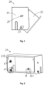
- the present application provides a storage box 20, comprising an enclosure 21, a storage box body 22, a pivot shaft 23 connected to the enclosure 21 and the storage box body 22, an elastic element, and a locking device.
- the storage box body 22 is formed with a cavity for storing items, the enclosure 21 has an opening on one side, and the storage box body 22 is turnable outward about the pivot shaft 23 from the opening to open.
- the pivot shaft 23 is fixedly disposed on side walls of the enclosure 21, the side walls of the storage box body 22 are each provided with a pivot hole 221, the pivot shaft 23 is inserted into the pivot holes 221, and the pivot shaft 23 rotates in the pivot holes 221 so that the storage box body 22 pivots relative to the enclosure 21, thereby helping the user to take out the items from the storage box body 22.
- the elastic element is disposed between the pivot shaft 23 and the enclosure 21, and the elastic element always provides a driving force driving the storage box body 22 to turn outwards the enclosure 21 about the pivot shaft 23.
- the storage box body 22 can be automatically opened under the action of the elastic element, and the user needn't manually open the storage box body 22, so that the user experience can be improved.
- the elastic element is a torsion spring 25.
- the torsion spring 25 comprises a spring body 251, and a spring arm 252 connected to the spring body 251.
- the spring body 251 is sleeved on the pivot shaft 23.
- the torsion spring 25 can make the storage box body 22 in an open state, and the user may take items out of the cavity without holding the storage box body.
- the enclosure 21 comprises a fixing portion 213 connected to the side wall of the enclosure 21, the fixing portion 213 is provided with a through hole, the spring arm 252 passes through the through hole, and the through hole catches the spring arm 252, thereby improving the stability of the torsion spring 25.
- the locking device can lock or unlock the enclosure 21 to the storage box body 22. It may be appreciated that when the locking device locks, the elastic element cannot make the storage box body 22 open, so that the closeness of the storage box 20 may be maintained; when the locking device unlocks, the elastic element can make the storage box body 22 open, which is convenient for users to use.
- the locking device comprises a locking portion and a fitting portion which is push-fitted with the locking portion.
- One of the locking portion and the fitting portion is disposed on the enclosure 21, and the other is disposed on the storage box body 22.
- the fitting portion is a lock tongue 222 provided on a rear wall of the storage box body 22, and the locking portion is a push lock 211 provided on a rear wall of the enclosure 21.
- the lock tongue 222 extends into the push lock 211; when the storage box body 22 is in the open state, the lock tongue 222 separates from the push lock 211.
- the push lock 211 comprises a first force receiving portion 2111, a second force receiving portion 2113, and a resisting portion 2112.
- the first force receiving portion 2111 causes the resisting portion 2112 to release the lock tongue 222
- the second force receiving portion 2113 causes the resisting portion 2112 to clamp the lock tongue 222.
- the user may apply a push elastic force to any position of the front wall of the storage box body 22, and the push elastic force may be transferred to the first force receiving part 2111 to cause the resisting portion 2112 to release the lock tongue 222 to open the storage box body 22.
- the resisting portion 2112 clamps the lock tongue 222.
- the resisting portion 2112 is provided with a first protrusion
- the lock tongue 222 is provided with a second protrusion.
- the first protrusion abuts against the second protrusion so that the second protrusion cannot cross the first protrusion, such that the lock tongue 222 is locked in the push lock 211.
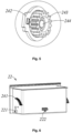
- the storage box 20 further comprises a damping device 24 connected to the enclosure 21 and the storage box body 22, and the damping device 24 provides a resistance against the turn of the storage box body 22 outward the enclosure 21.
- the damping device 24 can reduce a turning speed of the storage box body 22, so that the storage box body 22 can slowly open and the storage box body 22, thereby preventing damages of the storage box body 22 and the enclosure 21 caused by the storage box body 22 violently stroking the enclosure 21 due to an excessive turning speed.
- the damping device 24 comprises a rotary damper 242, a gear 243, and an arc-shaped rack 241.
- the rotary damper 242 is fixedly connected to a side wall of the enclosure 21, the gear 243 is fixedly connected to a damping rotation shaft 244 of the rotary damper 242, the arc-shaped rack 241 is fixedly connected to the side wall of the storage box body 22, and the arc-shaped rack 241 meshes with the gear 243.
- the arc-shaped rack 241 rotates and drives the gear 243 to rotate, then the gear 243 drives the damping rotation shaft 244 to rotate, the damping rotation shaft 244 has a rotational damping force, and the storage box body 22 receives the rotational damping force so that the opening speed of the storage box body 22 is reduced.
- the storage box 20 further comprises a buffer structure.
- the buffer structure can further prevent damages caused by the storage box body 22 striking the enclosure 21, and reduce the noise generated when the storage box body 22 strikes the enclosure 21.
- the buffer structure is a rubber member 212 disposed on the enclosure 21.
- the rubber member 212 can cooperate with the front wall of the storage box body 22 to prevent the storage box body 22 from violently striking the enclosure 21.
- the buffer structure may also be disposed on the storage box body 22, and may also be any of other members functioning to buffer, such as a sponge.
- the present application further provides a refrigerator, comprising a door body 10, wherein the storage box 20 is disposed on an inner side of the door body 10.
- gear 243 and an arc-shaped rack 241.
- the rotary damper 242 is fixedly connected to a side wall of the enclosure 21, the gear 243 is fixedly connected to a damping rotation shaft 244 of the rotary damper 242, the arc-shaped rack 241 is fixedly connected to the side wall of the storage box body 22, and the arc-shaped rack 241 meshes with the gear 243.
- the arc-shaped rack 241 rotates and drives the gear 243 to rotate, then the gear 243 drives the damping rotation shaft 244 to rotate, the damping rotation shaft 244 has a rotational damping force, and the storage box body 22 receives the rotational damping force so that the opening speed of the storage box body 22 is reduced.
- the storage box 20 further comprises a buffer structure.
- the buffer structure can further prevent damages caused by the storage box body 22 striking the enclosure 21, and reduce the noise generated when the storage box body 22 strikes the enclosure 21.
- the buffer structure is a rubber member 212 disposed on the enclosure 21.
- the rubber member 212 can cooperate with the front wall of the storage box body 22 to prevent the storage box body 22 from violently striking the enclosure 21.
- the buffer structure may also be disposed on the storage box body 22, and may also be any of other members functioning to buffer, such as a sponge.
- the present application further provides a refrigerator, comprising a door body 10, wherein the storage box 20 is disposed on an inner side of the door body 10.
Landscapes
- Engineering & Computer Science (AREA)
- Chemical & Material Sciences (AREA)
- Combustion & Propulsion (AREA)
- Physics & Mathematics (AREA)
- Mechanical Engineering (AREA)
- Thermal Sciences (AREA)
- General Engineering & Computer Science (AREA)
- Refrigerator Housings (AREA)
Claims (6)
- Boîte de stockage (20), comprenant une enceinte (21), un corps (22) de boîte de stockage, un axe pivot (23) relié à l'enceinte (21) et au corps (22) de boîte de stockage, dans laquelle la boîte de stockage (20) comprend en outre :un élément élastique disposé entre l'axe pivot (23) et l'enceinte (21), l'élément élastique fournissant en permanence une force d'entraînement amenant le corps (22) de boîte de stockage à tourner vers l'extérieur de l'enceinte (21) autour de l'axe pivot (23) ; l'élément élastique est un ressort de torsion (25), le ressort de torsion (25) comprend un corps (251) de ressort et un bras (252) de ressort relié au corps (251) de ressort ;caractérisé en ce que le corps (251) de ressort est enfilé sur l'axe pivot (23) ;et dans laquelle, en outre, la boîte de stockage comprend un dispositif de verrouillage, le dispositif de verrouillage comprenant une partie de verrouillage et une partie d'ajustement qui est ajustée par pression sur la partie de verrouillage, dans laquelle l'une de la partie de verrouillage et de la partie d'ajustement est disposée sur l'enceinte (21), et l'autre est disposée sur le corps (22) de boîte de stockage ; la partie d'ajustement est une languette de verrouillage (222) fournie sur une paroi arrière du corps (22) de boîte de stockage, et la partie de verrouillage est un verrou-poussoir (211) fourni sur une paroi arrière de l'enceinte (21) ; le verrou-poussoir (211) comprend une première partie de réception de force (2111), une seconde partie de réception de force (2113) et une partie résistante (2112), la première partie de réception de force (2111) amène la partie résistante (2112) à libérer la languette de verrouillage (222), et la seconde partie de réception de force (2113) amène la partie résistante (2112) à serrer la languette de verrouillage (222), un dispositif d'amortissement (24) relié à l'enceinte (21) et au corps (22) de boîte de stockage, et le dispositif d'amortissement (24) fournit une résistance contre la rotation du corps (22) de boîte de stockage vers l'extérieur de l'enceinte (21).
- Boîte de stockage selon la revendication 1, dans laquelle l'enceinte (21) comprend une partie de fixation (213) reliée à une paroi latérale de l'enceinte (21), la partie de fixation (213) est munie d'un trou traversant, et le bras (252) de ressort passe à travers le trou traversant.
- Boîte de stockage selon la revendication 1, dans laquelle la partie résistante (2112) est munie d'une première saillie, et la languette de verrouillage (222) est munie d'une seconde saillie.
- Boîte de stockage selon la revendication 1, dans laquelle le dispositif d'amortissement (24) comprend : un amortisseur rotatif (242) relié à demeure à une paroi latérale de l'enceinte (21) ;une roue dentée (243) reliée à demeure à un arbre rotatif d'amortissement (244) de l'amortisseur rotatif (242) ;une crémaillère arquée (241) reliée à demeure à la paroi latérale du corps (22) de boîte de stockage et s'engrenant avec la roue dentée (243).
- Boîte de stockage selon la revendication 1, dans laquelle la boîte de stockage (20) comprend en outre une structure antichoc qui est un élément en caoutchouc (212) disposé sur l'enceinte (21).
- Réfrigérateur, comprenant un corps de porte, dans lequel la boîte de stockage (20) selon la revendication 1 est disposée sur un côté intérieur du corps (10) de porte.
Applications Claiming Priority (2)
| Application Number | Priority Date | Filing Date | Title |
|---|---|---|---|
| CN202020440045.1U CN212205306U (zh) | 2020-03-30 | 2020-03-30 | 储物盒及具有其的冰箱 |
| PCT/CN2021/070215 WO2021196813A1 (fr) | 2020-03-30 | 2021-01-05 | Boîte de stockage et réfrigérateur le comprenant |
Publications (3)
| Publication Number | Publication Date |
|---|---|
| EP4130625A1 EP4130625A1 (fr) | 2023-02-08 |
| EP4130625A4 EP4130625A4 (fr) | 2023-08-23 |
| EP4130625B1 true EP4130625B1 (fr) | 2025-04-30 |
Family
ID=73824881
Family Applications (1)
| Application Number | Title | Priority Date | Filing Date |
|---|---|---|---|
| EP21781486.2A Active EP4130625B1 (fr) | 2020-03-30 | 2021-01-05 | Boîte de stockage et réfrigérateur le comprenant |
Country Status (4)
| Country | Link |
|---|---|
| US (1) | US20230160628A1 (fr) |
| EP (1) | EP4130625B1 (fr) |
| CN (1) | CN212205306U (fr) |
| WO (1) | WO2021196813A1 (fr) |
Families Citing this family (2)
| Publication number | Priority date | Publication date | Assignee | Title |
|---|---|---|---|---|
| CN212205306U (zh) * | 2020-03-30 | 2020-12-22 | 青岛海尔电冰箱有限公司 | 储物盒及具有其的冰箱 |
| CN116812360B (zh) * | 2022-03-22 | 2025-08-05 | 青岛海尔电冰箱有限公司 | 制冷装置 |
Family Cites Families (22)
| Publication number | Priority date | Publication date | Assignee | Title |
|---|---|---|---|---|
| JPS5946589B2 (ja) * | 1980-12-17 | 1984-11-13 | 株式会社ニフコ | 灰皿装置 |
| US4458379A (en) * | 1982-03-10 | 1984-07-10 | General Motors Corporation | Closure panel hinge and hold open mechanism |
| FR2549123B1 (fr) * | 1983-07-11 | 1985-12-13 | Peugeot | Agencement sur un support d'un cendrier ou autre organe mobile, muni d'un dispositif de verrouillage |
| US4513877A (en) * | 1984-07-02 | 1985-04-30 | Shiseido Co., Ltd. | Container having spring biased hinge |
| JPH0659810B2 (ja) * | 1984-11-21 | 1994-08-10 | 株式会社ニフコ | 車室内収納箱の開閉装置 |
| DE29519963U1 (de) * | 1995-12-16 | 1997-04-10 | AEG Hausgeräte GmbH, 90429 Nürnberg | Kühl- und/oder Gefriergerät |
| JP3451156B2 (ja) * | 1995-12-19 | 2003-09-29 | 本田技研工業株式会社 | 自動車の天井用小物入れ |
| JP4208280B2 (ja) * | 1997-12-19 | 2009-01-14 | 三洋電機株式会社 | 貯蔵庫 |
| US7715627B2 (en) * | 2005-03-25 | 2010-05-11 | Siemens Medical Solutions Usa, Inc. | Automatic determination of the standard cardiac views from volumetric data acquisitions |
| JP2008290565A (ja) * | 2007-05-24 | 2008-12-04 | Honda Motor Co Ltd | 車両用収納装置 |
| WO2009027443A2 (fr) * | 2007-08-31 | 2009-03-05 | Arcelik Anonim Sirketi | Appareil réfrigérant |
| EP2594876A2 (fr) * | 2011-11-15 | 2013-05-22 | LG Electronics | Réfrigérateur |
| CN102564042B (zh) * | 2012-01-20 | 2016-12-14 | 海尔集团公司 | 冰箱储物盒及冰箱 |
| CN102538373A (zh) * | 2012-03-01 | 2012-07-04 | 合肥美的荣事达电冰箱有限公司 | 储物盒组件和冰箱 |
| KR20140008597A (ko) * | 2012-07-09 | 2014-01-22 | 삼성전자주식회사 | 래치장치 및 이를 갖는 냉장고 |
| CN104344676B (zh) * | 2014-03-03 | 2017-01-18 | 海尔集团公司 | 储物盒组件和具有该储物盒组件的冰箱 |
| CN204806818U (zh) * | 2015-06-11 | 2015-11-25 | 广州美的华凌冰箱有限公司 | 储物盒组件及冰箱 |
| CN106568289A (zh) * | 2016-11-15 | 2017-04-19 | 青岛海尔股份有限公司 | 冰箱及其储物盒 |
| US10232789B2 (en) * | 2016-12-09 | 2019-03-19 | Ford Global Technologies Llc | Integrated latch/bumper combination |
| CN106958982A (zh) * | 2017-03-21 | 2017-07-18 | 合肥华凌股份有限公司 | 翻转盒组件及冰箱 |
| US10458696B1 (en) * | 2018-04-04 | 2019-10-29 | Whirlpool Corporation | Opening system for a storage bin assembly |
| CN212205306U (zh) * | 2020-03-30 | 2020-12-22 | 青岛海尔电冰箱有限公司 | 储物盒及具有其的冰箱 |
-
2020
- 2020-03-30 CN CN202020440045.1U patent/CN212205306U/zh active Active
-
2021
- 2021-01-05 EP EP21781486.2A patent/EP4130625B1/fr active Active
- 2021-01-05 US US17/916,147 patent/US20230160628A1/en not_active Abandoned
- 2021-01-05 WO PCT/CN2021/070215 patent/WO2021196813A1/fr not_active Ceased
Also Published As
| Publication number | Publication date |
|---|---|
| WO2021196813A1 (fr) | 2021-10-07 |
| US20230160628A1 (en) | 2023-05-25 |
| CN212205306U (zh) | 2020-12-22 |
| EP4130625A4 (fr) | 2023-08-23 |
| EP4130625A1 (fr) | 2023-02-08 |
Similar Documents
| Publication | Publication Date | Title |
|---|---|---|
| KR100857605B1 (ko) | 냉장고 | |
| CN102374716B (zh) | 用于储冰盒的门组件 | |
| JP3052152B2 (ja) | 自動車のコンソールボックス用等の両開き開閉装置 | |
| EP4130625B1 (fr) | Boîte de stockage et réfrigérateur le comprenant | |
| US7513582B2 (en) | Slide rail stopper having anti-opening and self-closing functions | |
| CN106568289A (zh) | 冰箱及其储物盒 | |
| EP2193320B1 (fr) | Appareil réfrigérant | |
| CN109708416B (zh) | 抽屉组件 | |
| KR101248297B1 (ko) | 홈바 도어의 개폐장치 | |
| KR200166856Y1 (ko) | 양방향으로개폐가능한냉장고도어 | |
| EP1684039B1 (fr) | Meuble frigorifique avec appareil pour tenir une porte entrouverte | |
| KR100728381B1 (ko) | 냉장고용 홈바 | |
| CN110409133B (zh) | 用于盖体的锁闭装置、洗衣设备的上盖结构及洗衣设备 | |
| KR101339922B1 (ko) | 냉장고 | |
| KR100549070B1 (ko) | 저장고 | |
| KR100469789B1 (ko) | 김치냉장고의 보조선반 | |
| KR102740261B1 (ko) | 비상 개방 가능한 금고 | |
| JP4511985B2 (ja) | 貯蔵庫 | |
| KR200322772Y1 (ko) | 냉장고의 홈 바 도어의 도어 체커 | |
| KR20060004554A (ko) | 밀폐 기구용 도어의 개방 각도 정지 장치 | |
| KR101034199B1 (ko) | 냉장고 | |
| KR20060111002A (ko) | 냉장고용 홈바 | |
| KR20050052709A (ko) | 서랍식 도어용 토글힌지 | |
| JPH0530378U (ja) | 扉のロツク装置 | |
| JP2006029043A (ja) | 地震時ロック装置とこれを有する収納ボックス |
Legal Events
| Date | Code | Title | Description |
|---|---|---|---|
| STAA | Information on the status of an ep patent application or granted ep patent |
Free format text: STATUS: THE INTERNATIONAL PUBLICATION HAS BEEN MADE |
|
| PUAI | Public reference made under article 153(3) epc to a published international application that has entered the european phase |
Free format text: ORIGINAL CODE: 0009012 |
|
| STAA | Information on the status of an ep patent application or granted ep patent |
Free format text: STATUS: REQUEST FOR EXAMINATION WAS MADE |
|
| 17P | Request for examination filed |
Effective date: 20220330 |
|
| AK | Designated contracting states |
Kind code of ref document: A1 Designated state(s): AL AT BE BG CH CY CZ DE DK EE ES FI FR GB GR HR HU IE IS IT LI LT LU LV MC MK MT NL NO PL PT RO RS SE SI SK SM TR |
|
| DAV | Request for validation of the european patent (deleted) | ||
| DAX | Request for extension of the european patent (deleted) | ||
| REG | Reference to a national code |
Ref country code: DE Free format text: PREVIOUS MAIN CLASS: F25D0025000000 Ref country code: DE Ref legal event code: R079 Ref document number: 602021030085 Country of ref document: DE Free format text: PREVIOUS MAIN CLASS: F25D0025000000 Ipc: F25D0023040000 |
|
| A4 | Supplementary search report drawn up and despatched |
Effective date: 20230726 |
|
| RIC1 | Information provided on ipc code assigned before grant |
Ipc: F25D 23/04 20060101AFI20230720BHEP |
|
| GRAP | Despatch of communication of intention to grant a patent |
Free format text: ORIGINAL CODE: EPIDOSNIGR1 |
|
| STAA | Information on the status of an ep patent application or granted ep patent |
Free format text: STATUS: GRANT OF PATENT IS INTENDED |
|
| RIC1 | Information provided on ipc code assigned before grant |
Ipc: F25D 23/04 20060101AFI20241106BHEP |
|
| INTG | Intention to grant announced |
Effective date: 20241206 |
|
| GRAS | Grant fee paid |
Free format text: ORIGINAL CODE: EPIDOSNIGR3 |
|
| GRAA | (expected) grant |
Free format text: ORIGINAL CODE: 0009210 |
|
| STAA | Information on the status of an ep patent application or granted ep patent |
Free format text: STATUS: THE PATENT HAS BEEN GRANTED |
|
| AK | Designated contracting states |
Kind code of ref document: B1 Designated state(s): AL AT BE BG CH CY CZ DE DK EE ES FI FR GB GR HR HU IE IS IT LI LT LU LV MC MK MT NL NO PL PT RO RS SE SI SK SM TR |
|
| REG | Reference to a national code |
Ref country code: CH Ref legal event code: EP Ref country code: GB Ref legal event code: FG4D |
|
| REG | Reference to a national code |
Ref country code: IE Ref legal event code: FG4D |
|
| REG | Reference to a national code |
Ref country code: DE Ref legal event code: R096 Ref document number: 602021030085 Country of ref document: DE |
|
| REG | Reference to a national code |
Ref country code: NL Ref legal event code: MP Effective date: 20250430 |
|
| REG | Reference to a national code |
Ref country code: AT Ref legal event code: MK05 Ref document number: 1790347 Country of ref document: AT Kind code of ref document: T Effective date: 20250430 |
|
| PG25 | Lapsed in a contracting state [announced via postgrant information from national office to epo] |
Ref country code: PT Free format text: LAPSE BECAUSE OF FAILURE TO SUBMIT A TRANSLATION OF THE DESCRIPTION OR TO PAY THE FEE WITHIN THE PRESCRIBED TIME-LIMIT Effective date: 20250901 Ref country code: ES Free format text: LAPSE BECAUSE OF FAILURE TO SUBMIT A TRANSLATION OF THE DESCRIPTION OR TO PAY THE FEE WITHIN THE PRESCRIBED TIME-LIMIT Effective date: 20250430 Ref country code: FI Free format text: LAPSE BECAUSE OF FAILURE TO SUBMIT A TRANSLATION OF THE DESCRIPTION OR TO PAY THE FEE WITHIN THE PRESCRIBED TIME-LIMIT Effective date: 20250430 |
|
| REG | Reference to a national code |
Ref country code: LT Ref legal event code: MG9D |
|
| PG25 | Lapsed in a contracting state [announced via postgrant information from national office to epo] |
Ref country code: NO Free format text: LAPSE BECAUSE OF FAILURE TO SUBMIT A TRANSLATION OF THE DESCRIPTION OR TO PAY THE FEE WITHIN THE PRESCRIBED TIME-LIMIT Effective date: 20250730 Ref country code: GR Free format text: LAPSE BECAUSE OF FAILURE TO SUBMIT A TRANSLATION OF THE DESCRIPTION OR TO PAY THE FEE WITHIN THE PRESCRIBED TIME-LIMIT Effective date: 20250731 |
|
| PG25 | Lapsed in a contracting state [announced via postgrant information from national office to epo] |
Ref country code: NL Free format text: LAPSE BECAUSE OF FAILURE TO SUBMIT A TRANSLATION OF THE DESCRIPTION OR TO PAY THE FEE WITHIN THE PRESCRIBED TIME-LIMIT Effective date: 20250430 Ref country code: PL Free format text: LAPSE BECAUSE OF FAILURE TO SUBMIT A TRANSLATION OF THE DESCRIPTION OR TO PAY THE FEE WITHIN THE PRESCRIBED TIME-LIMIT Effective date: 20250430 |
|
| PG25 | Lapsed in a contracting state [announced via postgrant information from national office to epo] |
Ref country code: BG Free format text: LAPSE BECAUSE OF FAILURE TO SUBMIT A TRANSLATION OF THE DESCRIPTION OR TO PAY THE FEE WITHIN THE PRESCRIBED TIME-LIMIT Effective date: 20250430 |
|
| PG25 | Lapsed in a contracting state [announced via postgrant information from national office to epo] |
Ref country code: HR Free format text: LAPSE BECAUSE OF FAILURE TO SUBMIT A TRANSLATION OF THE DESCRIPTION OR TO PAY THE FEE WITHIN THE PRESCRIBED TIME-LIMIT Effective date: 20250430 |
|
| PG25 | Lapsed in a contracting state [announced via postgrant information from national office to epo] |
Ref country code: AT Free format text: LAPSE BECAUSE OF FAILURE TO SUBMIT A TRANSLATION OF THE DESCRIPTION OR TO PAY THE FEE WITHIN THE PRESCRIBED TIME-LIMIT Effective date: 20250430 |
|
| PG25 | Lapsed in a contracting state [announced via postgrant information from national office to epo] |
Ref country code: RS Free format text: LAPSE BECAUSE OF FAILURE TO SUBMIT A TRANSLATION OF THE DESCRIPTION OR TO PAY THE FEE WITHIN THE PRESCRIBED TIME-LIMIT Effective date: 20250731 |
|
| PG25 | Lapsed in a contracting state [announced via postgrant information from national office to epo] |
Ref country code: IS Free format text: LAPSE BECAUSE OF FAILURE TO SUBMIT A TRANSLATION OF THE DESCRIPTION OR TO PAY THE FEE WITHIN THE PRESCRIBED TIME-LIMIT Effective date: 20250830 |
|
| PG25 | Lapsed in a contracting state [announced via postgrant information from national office to epo] |
Ref country code: LV Free format text: LAPSE BECAUSE OF FAILURE TO SUBMIT A TRANSLATION OF THE DESCRIPTION OR TO PAY THE FEE WITHIN THE PRESCRIBED TIME-LIMIT Effective date: 20250430 |
|
| PG25 | Lapsed in a contracting state [announced via postgrant information from national office to epo] |
Ref country code: SM Free format text: LAPSE BECAUSE OF FAILURE TO SUBMIT A TRANSLATION OF THE DESCRIPTION OR TO PAY THE FEE WITHIN THE PRESCRIBED TIME-LIMIT Effective date: 20250430 Ref country code: DK Free format text: LAPSE BECAUSE OF FAILURE TO SUBMIT A TRANSLATION OF THE DESCRIPTION OR TO PAY THE FEE WITHIN THE PRESCRIBED TIME-LIMIT Effective date: 20250430 |
|
| PG25 | Lapsed in a contracting state [announced via postgrant information from national office to epo] |
Ref country code: CZ Free format text: LAPSE BECAUSE OF FAILURE TO SUBMIT A TRANSLATION OF THE DESCRIPTION OR TO PAY THE FEE WITHIN THE PRESCRIBED TIME-LIMIT Effective date: 20250430 |
|
| PG25 | Lapsed in a contracting state [announced via postgrant information from national office to epo] |
Ref country code: EE Free format text: LAPSE BECAUSE OF FAILURE TO SUBMIT A TRANSLATION OF THE DESCRIPTION OR TO PAY THE FEE WITHIN THE PRESCRIBED TIME-LIMIT Effective date: 20250430 |
|
| PG25 | Lapsed in a contracting state [announced via postgrant information from national office to epo] |
Ref country code: SK Free format text: LAPSE BECAUSE OF FAILURE TO SUBMIT A TRANSLATION OF THE DESCRIPTION OR TO PAY THE FEE WITHIN THE PRESCRIBED TIME-LIMIT Effective date: 20250430 |
|
| PG25 | Lapsed in a contracting state [announced via postgrant information from national office to epo] |
Ref country code: IT Free format text: LAPSE BECAUSE OF FAILURE TO SUBMIT A TRANSLATION OF THE DESCRIPTION OR TO PAY THE FEE WITHIN THE PRESCRIBED TIME-LIMIT Effective date: 20250430 |
|
| REG | Reference to a national code |
Ref country code: DE Ref legal event code: R097 Ref document number: 602021030085 Country of ref document: DE |
|
| PLBE | No opposition filed within time limit |
Free format text: ORIGINAL CODE: 0009261 |
|
| STAA | Information on the status of an ep patent application or granted ep patent |
Free format text: STATUS: NO OPPOSITION FILED WITHIN TIME LIMIT |
|
| REG | Reference to a national code |
Ref country code: CH Ref legal event code: L10 Free format text: ST27 STATUS EVENT CODE: U-0-0-L10-L00 (AS PROVIDED BY THE NATIONAL OFFICE) Effective date: 20260311 |
|
| 26N | No opposition filed |
Effective date: 20260202 |
|
| PGFP | Annual fee paid to national office [announced via postgrant information from national office to epo] |
Ref country code: GB Payment date: 20260127 Year of fee payment: 6 |
|
| PGFP | Annual fee paid to national office [announced via postgrant information from national office to epo] |
Ref country code: DE Payment date: 20260114 Year of fee payment: 6 |
|
| PGFP | Annual fee paid to national office [announced via postgrant information from national office to epo] |
Ref country code: FR Payment date: 20260128 Year of fee payment: 6 |