EP2193593B1 - Statorstruktur - Google Patents
Statorstruktur Download PDFInfo
- Publication number
- EP2193593B1 EP2193593B1 EP08792360A EP08792360A EP2193593B1 EP 2193593 B1 EP2193593 B1 EP 2193593B1 EP 08792360 A EP08792360 A EP 08792360A EP 08792360 A EP08792360 A EP 08792360A EP 2193593 B1 EP2193593 B1 EP 2193593B1
- Authority
- EP
- European Patent Office
- Prior art keywords
- coil
- resin
- bus bar
- stator
- split
- Prior art date
- Legal status (The legal status is an assumption and is not a legal conclusion. Google has not performed a legal analysis and makes no representation as to the accuracy of the status listed.)
- Active
Links
Images







Classifications
-
- H—ELECTRICITY
- H02—GENERATION; CONVERSION OR DISTRIBUTION OF ELECTRIC POWER
- H02K—DYNAMO-ELECTRIC MACHINES
- H02K9/00—Arrangements for cooling or ventilating
- H02K9/19—Arrangements for cooling or ventilating for machines with closed casing and closed-circuit cooling using a liquid cooling medium, e.g. oil
-
- H—ELECTRICITY
- H02—GENERATION; CONVERSION OR DISTRIBUTION OF ELECTRIC POWER
- H02K—DYNAMO-ELECTRIC MACHINES
- H02K3/00—Details of windings
- H02K3/04—Windings characterised by the conductor shape, form or construction, e.g. with bar conductors
- H02K3/24—Windings characterised by the conductor shape, form or construction, e.g. with bar conductors with channels or ducts for cooling medium between the conductors
-
- H—ELECTRICITY
- H02—GENERATION; CONVERSION OR DISTRIBUTION OF ELECTRIC POWER
- H02K—DYNAMO-ELECTRIC MACHINES
- H02K3/00—Details of windings
- H02K3/46—Fastening of windings on the stator or rotor structure
- H02K3/52—Fastening salient pole windings or connections thereto
- H02K3/521—Fastening salient pole windings or connections thereto applicable to stators only
- H02K3/522—Fastening salient pole windings or connections thereto applicable to stators only for generally annular cores with salient poles
-
- H—ELECTRICITY
- H02—GENERATION; CONVERSION OR DISTRIBUTION OF ELECTRIC POWER
- H02K—DYNAMO-ELECTRIC MACHINES
- H02K9/00—Arrangements for cooling or ventilating
- H02K9/22—Arrangements for cooling or ventilating by solid heat conducting material embedded in, or arranged in contact with, the stator or rotor, e.g. heat bridges
-
- H—ELECTRICITY
- H02—GENERATION; CONVERSION OR DISTRIBUTION OF ELECTRIC POWER
- H02K—DYNAMO-ELECTRIC MACHINES
- H02K15/00—Processes or apparatus specially adapted for manufacturing, assembling, maintaining or repairing of dynamo-electric machines
- H02K15/12—Impregnating, moulding insulation, heating or drying of windings, stators, rotors or machines
-
- H—ELECTRICITY
- H02—GENERATION; CONVERSION OR DISTRIBUTION OF ELECTRIC POWER
- H02K—DYNAMO-ELECTRIC MACHINES
- H02K5/00—Casings; Enclosures; Supports
- H02K5/04—Casings or enclosures characterised by the shape, form or construction thereof
- H02K5/08—Insulating casings
-
- H—ELECTRICITY
- H02—GENERATION; CONVERSION OR DISTRIBUTION OF ELECTRIC POWER
- H02K—DYNAMO-ELECTRIC MACHINES
- H02K5/00—Casings; Enclosures; Supports
- H02K5/04—Casings or enclosures characterised by the shape, form or construction thereof
- H02K5/20—Casings or enclosures characterised by the shape, form or construction thereof with channels or ducts for flow of cooling medium
- H02K5/203—Casings or enclosures characterised by the shape, form or construction thereof with channels or ducts for flow of cooling medium specially adapted for liquids, e.g. cooling jackets
Definitions
- the present invention relates to a stator structure for a motor and more particularly to a stator structure with a high cooling capability.
- a motor used in a hybrid electric vehicle outputs high power and has a high space factor of coil for reduction in motor size. This may cause a problem in a temperature rise of the motor coil in use. Accordingly, a demand has been increased for a method of cooling the coil at a high cooling efficiency. When the temperature of the coil rises, a limiter for upper limit temperature is activated for system safety. Consequently, there may occur problems of deterioration in steep-hill climbing capability (gradeability), high-load steady running, and others.
- JP2004-215358A discloses a technique of directly cooling by air flow an annular bus bar exposed on a coil with a heat conductive insulating member interposed therebetween.
- Japanese Patent Application JP 2000 197311 discloses a coil cooling structure for a rotary electric machine. Within a resin mold for fixing coils to an outer core of a rotary electric machine, a neutral point bus bar forming the neutral point by connecting the winding end sides of the coils is formed in a hollow shape to form a cooling path.
- US Patent Application US 2004/056383 discloses a process for preparing an over moulded motor stator structure.
- US Patent Application US 2004/056383 discloses a process for preparing an over moulded motor stator structure.
- the present invention has been made to solve the above problems and has a purpose to provide a stator structure with a coil molded with resin and a cooling structure providing low cost and high productivity.
- one aspect of the present invention provides a stator structure comprising: a core; a plurality of coils each mounted on a tooth; a resin molded portion covering the coil; a bus bar connected to the coils; and a cooling unit for directly cooling the bus bar.
- Each coil has both ends protruding out of the resin molded portion, the bus bar connects the protruding ends of the coils, and the cooling unit has a cooling oil injection unit directly injecting the cooling oil toward the bus bar to cool the coil.
- the resin molded portion is formed with an uneven guiding part for guiding and positioning the bus bar.
- the core is constituted of a plurality of split cores, and each of the split cores is attached with the respective coil and molded with resin.
- the stator structure (1) preferably, further comprises a bus bar holder placed on an upper surface of the core located outside the coil to hold at least part of the bus bar, each end of the coil is bent and connected to the bus bar held by the bus bar holder.
- the stator structure of the invention is adapted such that a bus bar is connected to ends of a coil molded with resin so as to expose the ends, and a cooling unit is arranged to directly cool the bus bar.
- the bus bar can be cooled efficiently.
- the heat generated in the coil covered by the resin molded portion will be conducted to the bus bar because of the high heat conductivity of the coil.
- the bus bar will heat to a temperature almost equal to the temperature of the coil. Accordingly, direct cooling the bus bar can provide an effect of directly cooling the coil covered by the resin molded portion, thus restraining a temperature increase of the coil.
- the bus bar is not molded with resin and hence an amount of resin for resin molding can be reduced largely.
- the coil (a previously wound cassette coil portion) is resin-molded with its ends serving as terminals exposed and hence the coil portion of each coil can be protected against scratches. This can facilitate a work of wire-connecting the bus bars to the coil ends in later processes and enhance the productivity.
- coil terminals to be wire-connected are covered by separate protective caps or the like.
- the resin molded portion is formed with the uneven part for directing both ends of the bus bar to the coil terminals for wire connection. Accordingly, this makes it easy to attach the bus bars to the resin molded coils and further enhance the productivity.
- the split core on which the coil is mounted is molded with resin. It is therefore possible to resin-mold the coil with the coil ends being exposed and achieve a cost reduction.
- the stator structure of the invention may be applied to another configuration in which the bus bar holder is placed on the core upper surface located outside the coil to hold at least part of the bus bar, and the coil ends are bent and wire-connected to the bus bar held in the bus bar holder.
- This configuration does not need the uneven part for guide disclosed in the above configuration (2) and can form a resin molded portion in simpler shape.
- Fig. 1 is a view showing a sequence of manufacturing a split stator in a first embodiment according to the invention
- Fig. 1 shows a sequence of manufacturing a split stator.
- a split stator core (hereinafter, referred to as a "split core") 10 includes an arc-shaped base portion 10a and a tooth 11 protruding therefrom so that a formed coil is to be mounted around the tooth 11.
- This split core 10 is made by laminating steel sheets produced by press-punching.
- eighteen split cores 10 are to be assembled together to form an annular stator core so that the arc-shaped base portions 10a are circularly arranged with the teeth 11 each protruding radially inwardly.
- This split core 10 is shown in a state (a) of Fig. 1 . In a state (b) of Fig.
- an insulator 12 is fitted on the tooth 1 of the split core 10.
- the insulator 12 includes a rectangular sleeve part 12b which covers the tooth 11, a flange 12a which covers an inner surface of the base portion 10a other than the tooth 11 and vertically extends larger than the base portion 10a, and two ribs 12c protruding upward and downward from the sleeve part 12b.
- the thickness of each side wall of the insulator 12 is 0.2 mm to 0.3 mm in the embodiment.
- a state (c) of Fig. 1 shows that a formed edgewise coil 13 is mounted on the tooth 11 through the sleeve part 12b of the insulator 12.
- the edgewise coil 13 is made of a coil wire having a flat rectangular cross section and being wound by edgewise bending into a hollow shape with an inner diameter corresponding to the shape of the tooth 11.
- the edgewise coil 13 is placed in close contact with the split core 10 through the flange 12a.
- the edgewise coil 13 is positioned in place in a lateral direction by the tooth 11 through the sleeve part 12b and in a vertical direction by the ribs 12c of the insulator 12. Accordingly, the edgewise coil 13 is held in a fixed position relative to the split core 10.
- the edgewise coil 13 includes a long end 13a extending upward from a position close to the flange 12a and a long end 13b extending upward from a position close to a distal end face of the tooth 11.
- the long ends 13a and 13b serve as coil terminals.
- the edgewise coil 13 is a formed coil.
- other types of coils having for example circular section, rectangular section, or others, may be adopted if only a coil has a completely formed shape.
- FIG. 1 A state (d) of Fig. 1 shows a split stator 18 molded with resin.
- the edgewise coil 13 is coated with a resin molded portion (layer) 14.
- a resin molding technique thereof will be mentioned in detail later.
- the pair of long ends 13a and 13b protrudes out of the resin molded portion 14 of the split stator 18.
- the resin molded portion 14 is formed with two grooves 14b and 14c. These guide rib 14a and grooves 14b and 14c correspond to an uneven part for guide of the invention.
- Fig. 3 is a sectional view of the resin-molded split stator 18, showing a positional relationship between the edgewise coil 13 and the resin molded portion 14.
- the edgewise coil 13 is mounted on the split core 10 with the insulator 12 interposed therebetween, and then the resin molded portion 14 is formed to coat only a winding portion (a previously wound cassette coil portion) of the edgewise coil 13.
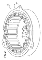
- Fig. 2 shows a stator 19 in which the eighteen split stators 18 are assembled together. Specifically, the eighteen split stators 18 are assembled in annular form, and an outer ring 15 heated and expanded in inner diameter is set around the split stators 18. Then, this assembly is cooled to a normal temperature, causing the outer ring 15 to shrink, decreasing its inner diameter. The eighteen split stators 18 are then constricted integrally to form the stator 19. This technique is a so-called shrink fitting of an outer ring.
- the bus bar 17 is set to connect a long end 18D13a of one split stator 18D with a long end 18A13b of a third split stator 18A by skipping two split stators 18C and 18B to the right.
- the long ends 13a and 13b of the eighteen split stators 18 are appropriately connected in this way through the bus bars 17 to constitute a motor coil with three U, V, and W phases.
- the bus bar 17 is Tig-welded to the long ends 18D13a and 18A13b respectively while it is engaged in the groove 14c of the guide rib 14a of the split stator 18C and the groove 14b of the guide rib 14a of the split stator 18B.
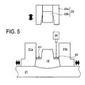
- FIG. 5 shows a structure of a molding die for forming the insulator 12.
- Fig. 6 shows a structure of a molding die for forming the resin molded portion 14. For easy viewing, those figures are not applied with hatching lines indicating sections.
- the split core 10 is held by a lower die 21 in four side directions (only two of them are shown), using an appropriate slide core selected from various slide cores configured to hold a workpiece in two, three, or four sides directions.
- the core 10 is fixedly held between a pair of lower slide cores 21a and 21b.
- an upper die 22 is moved down.
- This upper die 22 includes a guide core 22a and a leading slide core 22b which is guided by the guide core 22a to vertically slide.
- the slide core 22b is urged downward by a spring or the like.
- a supply device 24 is disposed between the upper die 22 and the lower die 21 so as to be movable to a standby position.
- the guide core 22a is further moved downward, providing a cavity for forming the insulator 12.
- the insulator material 25 is molded into the insulator 12 as shown in Fig. 1(b) .
- FIG. 6 the lower die 21 and the lower slide cores 21a and 21b are the same in structure as those in Fig. 5 .
- a guide core 26a of an upper die 26 is the same as the guide core 22a in Fig. 5 .
- a leading slide core 26b which is guided by the guide core 26a to vertically slide has a lower surface for forming a cavity of different shape from the slide core 22b in Fig. 5 .
- the slide core 26b is also urged downward by a spring or the like.
- a supply device 27 is disposed between the lower die 21 and the upper die 26 so as to be movable to a standby position.
- the edgewise coil 13 is set in a cavity K2. Accordingly, the long ends 13a and 13b of the edgewise coil 13 have to be shielded in an appropriate manner.
- a shielding structure is shown in Fig. 7 .
- the molding die in order to allow automatic setting of the edgewise coil 13 in the resin molding die, the molding die is designed to shield over the long ends 13a and 13b serving as coil terminals up to respective proximal portions.
- the lower die 21 is formed with a deep groove 21d at a position to receive the long end 13a of the edgewise coil 13 extending from the cavity of the lower die 21.
- the upper die 26 is formed with a long protrusion 26e. Those deep groove 21d and long protrusion 26e shield the periphery of the long end 13a.
- the lower die 21 is further formed with a shallow groove 21c at a position to receive the long end 13b extending from the cavity.
- the upper die 26 is correspondingly formed with a short protrusion 26d. Those shallow groove 21c and short protrusion 26d shield the periphery of the long end 13b.
- the dies are provided, on contact surfaces, with a cushioning member such as elastomer as needed.
- Fig. 8 shows another shielding structure, corresponding to only a circled portion A indicated with a dashed line in Fig. 7 .
- a parting line 29 between the upper die 26 and the lower die 21 is defined as an inclined (stepped) plane, not a flat plane, between the long ends 13a and 13b existing at different levels in section. Accordingly, this method enables shielding of the periphery of each long end 13a, 13b without forming the long protrusion 26e.
- the guide core 26a of the upper die 26 is further moved downward, providing a cavity for forming the resin molded portion 14.
- the cavity K2 includes the edgewise coil 13 and is larger than the cavity K1.
- the resin molding material 28 is supplied in the cavity K2 and molded into the shape of the resin molded portion 14 as shown in Fig. 1 (d) .
- FIG. 9 shows this stator structure 1.
- the stator 19 is secured to a casing 31 providing a sealed space by a bolt inserted in a mounting hole 15a of the outer ring 15.
- the casing 31 holds a rotor shaft 33 rotatably through a bearing 38.
- the casing 31 holds a predetermined amount of cooling oil 32.
- the casing 31 is formed with a feed passage 35 for feeding the cooling oil 32 to a pump 34 and an output passage 36 for outputting the cooling oil 32 from the pump 34.
- the output passage 36 communicates with a plurality of injection holes 37 circularly arranged to face the long ends 13a and 13b and the bus bars 17.
- the cooling oil 32 is thus directly injected through the injection holes 37 toward the long ends 13a and 13b and the bus bars 17 to directly cool them.
- the cooling oil 32 will drop down into a cooling-oil reservoir.
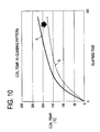
- Fig. 10 is a graph showing the effects resulting from the use of the stator structure 1 of the present embodiment as shown in Fig. 9 .
- a vertical axis indicates the temperature of the edgewise coil 13 and a lateral axis indicates the elapsed time of activation of the motor at constant voltage and current.
- a line A represents the result of a cooling test on a conventional stator of Fig. 13 with the cooling structure of Fig. 9 and a line B represents the result of a cooling test on the stator 18 of the present embodiment.
- the graph of Fig. 10 reveals that the present embodiment could provide so larger cooling effect of preventing a temperature increase of several tens of degree under the same condition of a hill-climbing pattern.
- the bus bars 17 are connected to the long ends 13a and 13b of the coils 13 each molded with resin with the long ends 13a and 13b extending so as not to be covered with resin.
- the stator structure 1 further includes the pump 34 and the injection holes 37 for directly cooling the bus bars 17. Accordingly, the cooling oil 32 is directly sprayed to the exposed bus bars 17, thereby efficiently cooling the bus bars 17.
- the heat generated in each coil 13 covered with the resin molded portion 14 is conducted to the bus bars 17 because of high heat conductivity of the coils 13 and hence the bus bars 17 heat to a temperature almost equal to the temperature of the coils 13.
- Each coil 13 is made of copper, which has heat conductivity as high as 400 W/mK. Accordingly, it can be cooled at extremely higher cooling efficiency than the resin molded portion having heat conductivity of the order of 0.2 to 2 W/mK.
- the coils 13 covered by the resin molded portions 14 can be directly cooled.
- the temperature increase of each coil 13 can be restrained.
- the cooling oil 32 is used as a cooling medium.
- the bus bars 17 are not covered with resin molding and therefore the amount of resin needed for molding can be reduced largely.
- each coil 13 is molded with resin so that the coil ends 13a and 13b are exposed.
- the winding portion (the previously wound cassette coil portion) of each coil 13 can therefore be protected against scratches. This can facilitate a work of wire-connecting the bus bars 17 to the coil ends 13a and 13b in later processes and enhance the productivity.
- coil terminals to be wire-connected are covered by separate protective caps or the line.
- the uneven part for guide (the guide rib 14a, the grooves 14b and 14c) are formed in each resin molded portion 14 to direct both ends of the bus bar 17 toward the relevant long ends 13a and 13b respectively for wire connection. This makes it easy to attach the bus bars 17 to the resin molded coils 13 and further enhance the productivity.
- the stator is constituted of a plurality of split cores divided per teeth and each split core is molded with resin. It is therefore easy to resin-mold the coil 13 with the ends 13a and 13b being exposed and achieve a cost reduction.
- the stator may be constituted of split cores each having one or more teeth.
- the formed coil 13 is fitted on the teeth 11 of the split core 10 with the insulator 12 interposed therebetween and the coil 13 is molded with resin, forming the resin molded portion 14 so that the long ends 13a and 13b remain exposed. An insulation performance of the coil 13 can be ensured.
- the split stators 18 of the present embodiment can be manufactured by individually molding eighteen winding portions with resin while sealing only two coil terminals of each coil. It is therefore possible to mold resin in only the space for each coil winding portion and hence cut down more than 40% of an amount of resin required for the resin molding.
- Fig. 13 is a sectional view showing a conventional resin molding configuration.
- a resin molded portion 14 is formed not only in the space for a winding portion of the coil 13 but also over the bus bars 17 together. It is found from the comparison between the configurations in Figs. 13 and 3 that the present embodiment could achieve a 40% reduction of resin molding material.
- the molding cavity in one resin molding is small in volume, so that resin of low fluidity can be used as it is.
- a motor for hybrid electric vehicle needing high torque will be supplied with relatively high voltage, thus generating a large amount of heat.
- the resin molded portion is required to have higher heat conductivity.
- an additive is added to the resin. This may decrease the resin fluidity, causing a technical difficulty in filling the resin in the molding cavity in every corner, particularly, in internal space (clearances) in a winding portion of the coil.
- the volume of the molding cavity is so small as to allow the resin to be filled throughout the internal space in the winding portion of the coil 13. This makes it possible to increase the efficiency of releasing heat generated in the coil 13 to the outside through the resin molded portion 14.
- the insulator 12 is integrally formed on the split core 10 by resin molding. That is, after the insulator 12 is molded from resin on the split core 10, the formed coil is inserted in the die and then molded with resin. By such a series of processes after the split stator core 10 is loaded in the lower molding die 21, the split stator 18 can be manufactured consecutively.
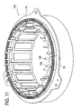
- FIG. 11 shows a stator 19A in which the eighteen split stators 18 of Fig. 12 are assembled together.
- Fig. 12 is a sectional view of the split stator 18.
- the eighteen split stators 18 are assembled in annular form, and the outer ring 15 heated and expanded in inner diameter is set around the split stators 18. Then, this assembly is cooled to a normal temperature, causing the outer ring 15 to shrink, decreasing its inner diameter. The eighteen split stators 18 are then constricted integrally to form the stator 19A. This technique is a so-called shrink fitting of an outer ring.
- the long end 13a of one split stator 18 is connected with the long end 13b of a third split stator 18 by skipping two split stators 18 to the left by means of the bus bar 17 (17A, 17B, or 17C) in the holder 16 (16A, 16B, or 16C).
- the long ends 13a and 13b of the eighteen split stators 18 are appropriately connected in this way through the bus bars 17 (17A, 17B, 17C) in the holders 16 (16A, 16B, 16C) to constitute a motor coil with three U, V, and W phases.
- the stator structure of the second embodiment is constituted merely by replacing the stator 19 shown in Fig. 9 with the stator 19A of Fig. 11 . Accordingly, the details thereof will not be repeated herein.
- the bus bar holder 16 holding at least part of the bus bar 17 is placed on the base portion 10a of the core 10 located outside the coil 13, and the long ends 13a and 13b of each coil 13 are bent to be connected to the bus bars 17 held in the holder 16.
- this embodiment does not need the uneven part for guide (the guide rib 14a, the grooves 14b and 14c) of the first embodiment, thereby enabling easier resin molding.
- the cooling oil 32 is used to cool the coils 13 but an air cooling technique may be adopted instead.
- the split stator 18 including a single edgewise coil 13.
- a split core having two teeth 11 may be adopted, in which two edgewise cores 13 are mounted on the teeth respectively, and all the split cores are assembled and entirely resin-molded.
- Another alternative is to employ a split stator core having three teeth 11 on which three edgewise coils 13 are mounted individually, and the split stator cores are assembled and entirely resin-molded.
- the present invention may be applied to any coil made of a coil wire having a circular, square, or different-shaped section as well as the edgewise coil if only it is finished as a formed coil.
Landscapes
- Engineering & Computer Science (AREA)
- Power Engineering (AREA)
- Manufacturing & Machinery (AREA)
- Insulation, Fastening Of Motor, Generator Windings (AREA)
- Iron Core Of Rotating Electric Machines (AREA)
- Manufacture Of Motors, Generators (AREA)
- Motor Or Generator Cooling System (AREA)
- Windings For Motors And Generators (AREA)
- Motor Or Generator Frames (AREA)
- Reciprocating, Oscillating Or Vibrating Motors (AREA)
Claims (4)
- Eine Statorstruktur (1), die aufweist:einen Kern mit einer Vielzahl von Zähnen (11),eine Vielzahl von Spulen (13), von denen jede an einem der Zähne (11) montiert ist,einen harzgeformten Abschnitt (14), der die Spulen (13) bedeckt,einen Busstab (17, 17A-17C), der mit den Spulen verbunden sind, undeine Kühleinheit (32-37) zum direkten Kühlen des Busstabes,dadurch gekennzeichnet, dass beide Enden (13a, 13b) jeder Spule (13) aus dem harzgeformten Abschnitt (14) hervorstehen,der Busstab (17, 17A-17C) die hervorstehenden Enden (13a, 13b) der Spulen (13) verbindet, unddie Kühleinheit eine Kühlöleinspritzeinheit (37) hat, die das Kühlöl (32) zu dem Busstab (17, 17A-17C) direkt einspritzt, um die Spule (13) zu kühlen.
- Die Statorstruktur nach Anspruch 1, wobei
der harzgeformte Abschnitt (14) mit einem unebenen Führungsteil (14a, 14b, 14c) zum Führen und Positionieren des Busstabes (17, 17A-17C) ausgebildet ist. - Die Statorstruktur nach Anspruch 2, wobei
der Kern durch eine Vielzahl von Unterteilungskernen (10) gebildet wird und jeder der Unterteilungskerne (10) seine jeweilige Spule (13) aufweist und mit dem harzgeformten Abschnitt (14) geformt ist. - Die Statorstruktur nach Anspruch 1, die ferner eine Busstabhalteeinrichtung (16, 16A-16C) aufweist, die an einer oberen Fläche des Kerns angeordnet, die sich außerhalb des Kerns (13) befindet, um zumindest einen Teil des Busstabes (17, 17A-17C) zu halten, wobei jedes Ende (13a, 13b) der Spule (13) gebogen ist und mit dem Busstab, der durch die Busstabhalteeinrichtung gehalten wird, verbunden ist.
Applications Claiming Priority (2)
| Application Number | Priority Date | Filing Date | Title |
|---|---|---|---|
| JP2007251976A JP4661849B2 (ja) | 2007-09-27 | 2007-09-27 | 固定子構造 |
| PCT/JP2008/064376 WO2009041172A2 (en) | 2007-09-27 | 2008-08-04 | Stator structure |
Publications (2)
| Publication Number | Publication Date |
|---|---|
| EP2193593A2 EP2193593A2 (de) | 2010-06-09 |
| EP2193593B1 true EP2193593B1 (de) | 2011-04-13 |
Family
ID=40379712
Family Applications (1)
| Application Number | Title | Priority Date | Filing Date |
|---|---|---|---|
| EP08792360A Active EP2193593B1 (de) | 2007-09-27 | 2008-08-04 | Statorstruktur |
Country Status (8)
| Country | Link |
|---|---|
| US (1) | US8575798B2 (de) |
| EP (1) | EP2193593B1 (de) |
| JP (1) | JP4661849B2 (de) |
| KR (1) | KR101095131B1 (de) |
| CN (1) | CN101836346B (de) |
| AT (1) | ATE505836T1 (de) |
| DE (1) | DE602008006220D1 (de) |
| WO (1) | WO2009041172A2 (de) |
Families Citing this family (54)
| Publication number | Priority date | Publication date | Assignee | Title |
|---|---|---|---|---|
| JP4840259B2 (ja) * | 2007-06-13 | 2011-12-21 | トヨタ自動車株式会社 | 絶縁部材 |
| JP5047224B2 (ja) * | 2009-05-20 | 2012-10-10 | 本田技研工業株式会社 | 電動機 |
| US8933602B2 (en) | 2009-06-26 | 2015-01-13 | Toyota Jidosha Kabushiki Kaisha | Stator structure and stator manufacturing method |
| JP2011030378A (ja) * | 2009-07-27 | 2011-02-10 | Panasonic Corp | ステータ及び電気機器 |
| JP5703604B2 (ja) | 2010-03-03 | 2015-04-22 | 日本電産株式会社 | バスバーユニット及びモータ |
| JP5740930B2 (ja) * | 2010-03-03 | 2015-07-01 | 日本電産株式会社 | ステータ及びモータ |
| JP5740931B2 (ja) * | 2010-03-03 | 2015-07-01 | 日本電産株式会社 | 分割ステータ、及びモータ |
| JP5652004B2 (ja) * | 2010-06-02 | 2015-01-14 | 日産自動車株式会社 | 配電構造部品およびその製造方法 |
| DE112011101912T5 (de) * | 2010-06-04 | 2013-03-28 | Remy Technologies Llc. | Kühlsystem und -verfahren für eine elektrische Maschine |
| US8970073B2 (en) * | 2010-10-19 | 2015-03-03 | Toyota Jidosha Kabushiki Kaisha | Cooling structure for rotary electric machine |
| JP5516562B2 (ja) | 2011-02-09 | 2014-06-11 | 株式会社豊田自動織機 | コイル、ステータ、コイルの製造方法 |
| DE102011004612B4 (de) | 2011-02-23 | 2023-08-31 | Robert Bosch Gmbh | Spule für eine Elektromaschine mit verbessertem Wicklungsfüllfaktor |
| JP5306411B2 (ja) * | 2011-05-23 | 2013-10-02 | 三菱電機株式会社 | 回転電機 |
| EP2560269A3 (de) * | 2011-08-16 | 2017-10-18 | LG Innotek Co., Ltd. | Stator für einen Motor |
| JP6079012B2 (ja) | 2011-09-09 | 2017-02-15 | アイシン精機株式会社 | 3相回転電機 |
| JP2013169029A (ja) * | 2012-02-14 | 2013-08-29 | Kobe Steel Ltd | 発電装置 |
| JP5603365B2 (ja) * | 2012-03-22 | 2014-10-08 | 三菱電機株式会社 | 回転電機 |
| JP6057050B2 (ja) * | 2012-03-23 | 2017-01-11 | 株式会社富士通ゼネラル | モールドモータ |
| US9698648B2 (en) * | 2012-06-14 | 2017-07-04 | Panasonic Intellectual Property Management Co., Ltd. | Motor |
| WO2013190588A1 (ja) * | 2012-06-18 | 2013-12-27 | パナソニック株式会社 | モータ |
| JP5554383B2 (ja) * | 2012-09-11 | 2014-07-23 | 三菱電機株式会社 | 回転電機の固定子、及びその固定子の製造方法 |
| US9893594B2 (en) | 2012-09-12 | 2018-02-13 | Mitsubishi Electric Corporation | Armature of rotating electrical machine and method for manufacturing same |
| DE102012223976A1 (de) * | 2012-12-20 | 2014-06-26 | Hilti Aktiengesellschaft | Stator gepresst mit Wickelkopfsupport |
| JP6017990B2 (ja) * | 2013-02-21 | 2016-11-02 | 株式会社日本自動車部品総合研究所 | 回転電機用ステータ |
| JP6221037B2 (ja) * | 2014-02-12 | 2017-11-01 | 日本電産テクノモータ株式会社 | モータおよび樹脂ケーシングの成型方法 |
| JP6357694B2 (ja) * | 2014-07-28 | 2018-07-18 | 株式会社明電舎 | 回転機 |
| JP6331950B2 (ja) * | 2014-10-14 | 2018-05-30 | アイシン精機株式会社 | ステータ |
| CN107431400B (zh) * | 2015-03-31 | 2019-06-14 | 三菱电机株式会社 | 旋转电机 |
| WO2016169703A1 (de) * | 2015-04-23 | 2016-10-27 | Magna powertrain gmbh & co kg | Elektrische maschine |
| JP5963928B1 (ja) * | 2015-08-28 | 2016-08-03 | 三菱電機株式会社 | 回転電機の結線ユニット |
| DE102016107929A1 (de) * | 2016-04-28 | 2017-11-02 | Wobben Properties Gmbh | Aluformspule und Wicklungsaufbau sowie Stator eines Generators einer Windenergieanlage und Verfahren zum Herstellen eines Stators |
| ES2835602T3 (es) | 2018-01-12 | 2021-06-22 | Carrier Corp | Máquina electromagnética |
| JP7038407B2 (ja) | 2018-02-08 | 2022-03-18 | 株式会社アスター | コイルユニット、ステータ部材、ステータ、モータおよびこれらの製造方法 |
| US20210320545A1 (en) * | 2018-08-03 | 2021-10-14 | Nidec Corporation | Stator and motor |
| KR102642858B1 (ko) * | 2018-08-10 | 2024-03-04 | 엘지이노텍 주식회사 | 인슐레이터 및 이를 포함하는 모터 |
| EP3852243A4 (de) * | 2018-09-14 | 2022-02-23 | Panasonic Intellectual Property Management Co., Ltd. | Motor und dafür verwendete spule |
| WO2020059909A1 (ko) * | 2018-09-20 | 2020-03-26 | 엘지전자 주식회사 | 전동기 및 이를 구비하는 지능형 동력생성모듈 |
| JP7265751B2 (ja) | 2019-02-19 | 2023-04-27 | 株式会社アスター | バスバー接合体の製造方法 |
| JP7373827B2 (ja) | 2019-02-19 | 2023-11-06 | 株式会社アスター | コイル接合体およびコイル接合体の製造方法 |
| JP7376902B2 (ja) | 2019-02-19 | 2023-11-09 | 株式会社アスター | コイル接合体およびコイル接合体の製造方法 |
| JP7417236B2 (ja) | 2019-05-08 | 2024-01-18 | 株式会社アスター | ステータ部材、ステータおよびモータ |
| WO2020254849A1 (ja) * | 2019-06-21 | 2020-12-24 | 日産自動車株式会社 | バスバーの冷却構造 |
| CN114846728A (zh) | 2019-12-27 | 2022-08-02 | 松下知识产权经营株式会社 | 线圈以及具备该线圈的定子、马达 |
| US11611255B2 (en) * | 2021-01-27 | 2023-03-21 | Hamilton Sundstrand Corporation | High-speed edge-wound rotor |
| KR102544770B1 (ko) * | 2021-03-09 | 2023-06-20 | 현대모비스 주식회사 | 모터용 고정자 및 그 고정자를 포함하는 모터 |
| US20240154483A1 (en) * | 2021-05-20 | 2024-05-09 | Mitsubishi Electric Corporation | Rotary electrical machine |
| JP7661817B2 (ja) * | 2021-07-21 | 2025-04-15 | トヨタ自動車株式会社 | モータジェネレータの冷却構造 |
| US11837917B2 (en) | 2022-01-28 | 2023-12-05 | Ge Aviation Systems Llc | Method and apparatus for cooling a rotor assembly |
| US12206292B2 (en) | 2022-01-28 | 2025-01-21 | Ge Aviation Systems Llc | Method and apparatus for cooling a rotor assembly |
| US11984766B2 (en) | 2022-01-28 | 2024-05-14 | Ge Aviation Systems Llc | Method and apparatus for cooling a rotor assembly |
| US12126224B2 (en) | 2022-01-28 | 2024-10-22 | Ge Aviation Systems Llc | Method and apparatus for cooling a rotor assembly |
| JP2025114884A (ja) * | 2022-06-23 | 2025-08-06 | パナソニックIpマネジメント株式会社 | ステータ及びモータ |
| JP2025117306A (ja) * | 2024-01-30 | 2025-08-12 | トヨタ自動車株式会社 | モータ |
| FR3166497A1 (fr) | 2024-09-16 | 2026-03-20 | Sonceboz Mechatronics Boncourt Sa | Dispositif d’entrainement à assemblage facilité |
Family Cites Families (20)
| Publication number | Priority date | Publication date | Assignee | Title |
|---|---|---|---|---|
| JPS6416238A (en) * | 1987-07-09 | 1989-01-19 | Fanuc Ltd | Method of cooling motor |
| JP2000197311A (ja) * | 1998-12-25 | 2000-07-14 | Toyota Motor Corp | 回転電機のコイル冷却構造 |
| DE10032622A1 (de) * | 2000-07-07 | 2002-01-17 | Putzmeister Ag | Stützausleger für fahrbare Arbeitsmaschinen und Autobetonpumpen mit solchen Stützauslegern |
| US6578278B2 (en) * | 2001-09-21 | 2003-06-17 | Vernon Ray Siefert Revocable Trust | Saddle protractor |
| JP3733316B2 (ja) * | 2001-10-26 | 2006-01-11 | 住友電装株式会社 | 車両用薄型ブラシレスモータの集中配電部材 |
| JP2003136756A (ja) * | 2001-10-31 | 2003-05-14 | Konica Corp | インクジェットプリンタ |
| JP2003259593A (ja) * | 2002-02-27 | 2003-09-12 | Minebea Co Ltd | 回転電機のステータ構造 |
| US7036206B2 (en) * | 2002-08-09 | 2006-05-02 | Delphi Technologies, Inc. | Process for preparing an over molded motor stator structure |
| JPWO2004019468A1 (ja) * | 2002-08-21 | 2005-12-15 | トヨタ自動車株式会社 | 車両用モータ |
| JP2004215358A (ja) * | 2002-12-27 | 2004-07-29 | Toyota Motor Corp | 多相モータ装置 |
| JP3903922B2 (ja) * | 2003-01-27 | 2007-04-11 | 株式会社デンソー | 回転電機の集中巻きステータコイル |
| JP3901104B2 (ja) * | 2003-02-14 | 2007-04-04 | トヨタ自動車株式会社 | ステータコイルモジュールおよびその製造方法ならびに回転電機、回転電機の製造方法 |
| JP2005160143A (ja) * | 2003-11-20 | 2005-06-16 | Toyota Motor Corp | 回転電機の固定子 |
| JP4586542B2 (ja) * | 2005-01-17 | 2010-11-24 | トヨタ自動車株式会社 | 回転電機 |
| JP4645200B2 (ja) | 2005-01-17 | 2011-03-09 | トヨタ自動車株式会社 | 回転電機のステータおよび回転電機 |
| US7210304B2 (en) * | 2005-02-09 | 2007-05-01 | General Motors Corporation | Cooling arrangements for integrated electric motor-inverters |
| US20060232143A1 (en) | 2005-04-15 | 2006-10-19 | Delaware Capital Formation | Over molded stator |
| JP4281733B2 (ja) | 2005-11-21 | 2009-06-17 | トヨタ自動車株式会社 | 電気モータの分割ステータ |
| JP4888558B2 (ja) * | 2007-06-13 | 2012-02-29 | トヨタ自動車株式会社 | 回転電機の冷却構造 |
| JP4404145B2 (ja) * | 2008-01-16 | 2010-01-27 | トヨタ自動車株式会社 | 分割固定子製造方法 |
-
2007
- 2007-09-27 JP JP2007251976A patent/JP4661849B2/ja active Active
-
2008
- 2008-08-04 AT AT08792360T patent/ATE505836T1/de not_active IP Right Cessation
- 2008-08-04 WO PCT/JP2008/064376 patent/WO2009041172A2/en not_active Ceased
- 2008-08-04 KR KR1020107006585A patent/KR101095131B1/ko active Active
- 2008-08-04 US US12/679,993 patent/US8575798B2/en active Active
- 2008-08-04 CN CN200880109274.7A patent/CN101836346B/zh active Active
- 2008-08-04 DE DE602008006220T patent/DE602008006220D1/de active Active
- 2008-08-04 EP EP08792360A patent/EP2193593B1/de active Active
Also Published As
| Publication number | Publication date |
|---|---|
| KR20100063734A (ko) | 2010-06-11 |
| DE602008006220D1 (de) | 2011-05-26 |
| JP4661849B2 (ja) | 2011-03-30 |
| KR101095131B1 (ko) | 2011-12-16 |
| JP2009089456A (ja) | 2009-04-23 |
| US20100194214A1 (en) | 2010-08-05 |
| EP2193593A2 (de) | 2010-06-09 |
| CN101836346B (zh) | 2014-05-07 |
| US8575798B2 (en) | 2013-11-05 |
| CN101836346A (zh) | 2010-09-15 |
| ATE505836T1 (de) | 2011-04-15 |
| WO2009041172A2 (en) | 2009-04-02 |
| WO2009041172A3 (en) | 2009-06-04 |
Similar Documents
| Publication | Publication Date | Title |
|---|---|---|
| US8575798B2 (en) | Bus bar cooling unit for stator structure | |
| CN107852058B (zh) | 绝缘树脂覆盖方法和定子 | |
| EP3166209B1 (de) | Stator für elektrische rotationsmaschine | |
| EP3095176B1 (de) | Stator für elektrisches rotationsmaschine | |
| US9099900B2 (en) | Electric machine module cooling system and method | |
| JP5505077B2 (ja) | 固定子製造方法 | |
| US8203240B2 (en) | Liquid cooled rotating electrical machine | |
| US10615671B2 (en) | Stator and method for manufacturing stator | |
| EP2182614B1 (de) | Verdrahtungskomponente für Motorspule | |
| EP2182615B1 (de) | Verdrahtungskomponente für Motorspule | |
| US20140015356A1 (en) | Segmented electric machine core secured with belt and method of manufacture | |
| KR20150095172A (ko) | 수지 케이싱의 성형 방법 및 모터 | |
| CN101051768B (zh) | 定子组件和制造方法 | |
| JP2016059209A (ja) | 電動流体ポンプ | |
| JP2014023387A (ja) | モータ及びモータ製造方法 | |
| KR20220109963A (ko) | 모터용 터미널 블록 | |
| CN106451871B (zh) | 电机 | |
| EP3595141A1 (de) | Stromversorgungseinheit und elektrische drehmaschine | |
| JP2005184959A (ja) | 電動機のリードフレーム及びこれを用いた配電部品 | |
| WO2021218996A1 (zh) | 电机定子组件、电机及电动工具 | |
| KR102748782B1 (ko) | 모터 냉각구조 및 그 제조방법 | |
| JP5982786B2 (ja) | コイル、該コイルを用いてなるステータ及び前記コイルの製造方法 | |
| JP2009142040A (ja) | 回転電機及び回転電機の製造方法 | |
| JP2024051297A (ja) | 配線部品及びその製造方法 | |
| JP2018068068A (ja) | 回転電機用端末モジュール |
Legal Events
| Date | Code | Title | Description |
|---|---|---|---|
| PUAI | Public reference made under article 153(3) epc to a published international application that has entered the european phase |
Free format text: ORIGINAL CODE: 0009012 |
|
| 17P | Request for examination filed |
Effective date: 20100325 |
|
| AK | Designated contracting states |
Kind code of ref document: A2 Designated state(s): AT BE BG CH CY CZ DE DK EE ES FI FR GB GR HR HU IE IS IT LI LT LU LV MC MT NL NO PL PT RO SE SI SK TR |
|
| AX | Request for extension of the european patent |
Extension state: AL BA MK RS |
|
| GRAP | Despatch of communication of intention to grant a patent |
Free format text: ORIGINAL CODE: EPIDOSNIGR1 |
|
| GRAS | Grant fee paid |
Free format text: ORIGINAL CODE: EPIDOSNIGR3 |
|
| GRAA | (expected) grant |
Free format text: ORIGINAL CODE: 0009210 |
|
| AK | Designated contracting states |
Kind code of ref document: B1 Designated state(s): AT BE BG CH CY CZ DE DK EE ES FI FR GB GR HR HU IE IS IT LI LT LU LV MC MT NL NO PL PT RO SE SI SK TR |
|
| REG | Reference to a national code |
Ref country code: GB Ref legal event code: FG4D |
|
| REG | Reference to a national code |
Ref country code: CH Ref legal event code: EP |
|
| REG | Reference to a national code |
Ref country code: IE Ref legal event code: FG4D |
|
| REF | Corresponds to: |
Ref document number: 602008006220 Country of ref document: DE Date of ref document: 20110526 Kind code of ref document: P |
|
| REG | Reference to a national code |
Ref country code: DE Ref legal event code: R096 Ref document number: 602008006220 Country of ref document: DE Effective date: 20110526 |
|
| REG | Reference to a national code |
Ref country code: NL Ref legal event code: VDEP Effective date: 20110413 |
|
| LTIE | Lt: invalidation of european patent or patent extension |
Effective date: 20110413 |
|
| PG25 | Lapsed in a contracting state [announced via postgrant information from national office to epo] |
Ref country code: HR Free format text: LAPSE BECAUSE OF FAILURE TO SUBMIT A TRANSLATION OF THE DESCRIPTION OR TO PAY THE FEE WITHIN THE PRESCRIBED TIME-LIMIT Effective date: 20110413 Ref country code: NO Free format text: LAPSE BECAUSE OF FAILURE TO SUBMIT A TRANSLATION OF THE DESCRIPTION OR TO PAY THE FEE WITHIN THE PRESCRIBED TIME-LIMIT Effective date: 20110713 Ref country code: PT Free format text: LAPSE BECAUSE OF FAILURE TO SUBMIT A TRANSLATION OF THE DESCRIPTION OR TO PAY THE FEE WITHIN THE PRESCRIBED TIME-LIMIT Effective date: 20110816 Ref country code: SE Free format text: LAPSE BECAUSE OF FAILURE TO SUBMIT A TRANSLATION OF THE DESCRIPTION OR TO PAY THE FEE WITHIN THE PRESCRIBED TIME-LIMIT Effective date: 20110413 Ref country code: LT Free format text: LAPSE BECAUSE OF FAILURE TO SUBMIT A TRANSLATION OF THE DESCRIPTION OR TO PAY THE FEE WITHIN THE PRESCRIBED TIME-LIMIT Effective date: 20110413 |
|
| PG25 | Lapsed in a contracting state [announced via postgrant information from national office to epo] |
Ref country code: IS Free format text: LAPSE BECAUSE OF FAILURE TO SUBMIT A TRANSLATION OF THE DESCRIPTION OR TO PAY THE FEE WITHIN THE PRESCRIBED TIME-LIMIT Effective date: 20110813 Ref country code: ES Free format text: LAPSE BECAUSE OF FAILURE TO SUBMIT A TRANSLATION OF THE DESCRIPTION OR TO PAY THE FEE WITHIN THE PRESCRIBED TIME-LIMIT Effective date: 20110724 Ref country code: AT Free format text: LAPSE BECAUSE OF FAILURE TO SUBMIT A TRANSLATION OF THE DESCRIPTION OR TO PAY THE FEE WITHIN THE PRESCRIBED TIME-LIMIT Effective date: 20110413 Ref country code: LV Free format text: LAPSE BECAUSE OF FAILURE TO SUBMIT A TRANSLATION OF THE DESCRIPTION OR TO PAY THE FEE WITHIN THE PRESCRIBED TIME-LIMIT Effective date: 20110413 Ref country code: BE Free format text: LAPSE BECAUSE OF FAILURE TO SUBMIT A TRANSLATION OF THE DESCRIPTION OR TO PAY THE FEE WITHIN THE PRESCRIBED TIME-LIMIT Effective date: 20110413 Ref country code: FI Free format text: LAPSE BECAUSE OF FAILURE TO SUBMIT A TRANSLATION OF THE DESCRIPTION OR TO PAY THE FEE WITHIN THE PRESCRIBED TIME-LIMIT Effective date: 20110413 Ref country code: GR Free format text: LAPSE BECAUSE OF FAILURE TO SUBMIT A TRANSLATION OF THE DESCRIPTION OR TO PAY THE FEE WITHIN THE PRESCRIBED TIME-LIMIT Effective date: 20110714 Ref country code: CY Free format text: LAPSE BECAUSE OF FAILURE TO SUBMIT A TRANSLATION OF THE DESCRIPTION OR TO PAY THE FEE WITHIN THE PRESCRIBED TIME-LIMIT Effective date: 20110413 Ref country code: SI Free format text: LAPSE BECAUSE OF FAILURE TO SUBMIT A TRANSLATION OF THE DESCRIPTION OR TO PAY THE FEE WITHIN THE PRESCRIBED TIME-LIMIT Effective date: 20110413 |
|
| PG25 | Lapsed in a contracting state [announced via postgrant information from national office to epo] |
Ref country code: MT Free format text: LAPSE BECAUSE OF FAILURE TO SUBMIT A TRANSLATION OF THE DESCRIPTION OR TO PAY THE FEE WITHIN THE PRESCRIBED TIME-LIMIT Effective date: 20110413 Ref country code: NL Free format text: LAPSE BECAUSE OF FAILURE TO SUBMIT A TRANSLATION OF THE DESCRIPTION OR TO PAY THE FEE WITHIN THE PRESCRIBED TIME-LIMIT Effective date: 20110413 |
|
| PG25 | Lapsed in a contracting state [announced via postgrant information from national office to epo] |
Ref country code: EE Free format text: LAPSE BECAUSE OF FAILURE TO SUBMIT A TRANSLATION OF THE DESCRIPTION OR TO PAY THE FEE WITHIN THE PRESCRIBED TIME-LIMIT Effective date: 20110413 Ref country code: CZ Free format text: LAPSE BECAUSE OF FAILURE TO SUBMIT A TRANSLATION OF THE DESCRIPTION OR TO PAY THE FEE WITHIN THE PRESCRIBED TIME-LIMIT Effective date: 20110413 |
|
| PLBE | No opposition filed within time limit |
Free format text: ORIGINAL CODE: 0009261 |
|
| STAA | Information on the status of an ep patent application or granted ep patent |
Free format text: STATUS: NO OPPOSITION FILED WITHIN TIME LIMIT |
|
| PG25 | Lapsed in a contracting state [announced via postgrant information from national office to epo] |
Ref country code: SK Free format text: LAPSE BECAUSE OF FAILURE TO SUBMIT A TRANSLATION OF THE DESCRIPTION OR TO PAY THE FEE WITHIN THE PRESCRIBED TIME-LIMIT Effective date: 20110413 Ref country code: RO Free format text: LAPSE BECAUSE OF FAILURE TO SUBMIT A TRANSLATION OF THE DESCRIPTION OR TO PAY THE FEE WITHIN THE PRESCRIBED TIME-LIMIT Effective date: 20110413 Ref country code: PL Free format text: LAPSE BECAUSE OF FAILURE TO SUBMIT A TRANSLATION OF THE DESCRIPTION OR TO PAY THE FEE WITHIN THE PRESCRIBED TIME-LIMIT Effective date: 20110413 Ref country code: DK Free format text: LAPSE BECAUSE OF FAILURE TO SUBMIT A TRANSLATION OF THE DESCRIPTION OR TO PAY THE FEE WITHIN THE PRESCRIBED TIME-LIMIT Effective date: 20110413 |
|
| 26N | No opposition filed |
Effective date: 20120116 |
|
| PG25 | Lapsed in a contracting state [announced via postgrant information from national office to epo] |
Ref country code: MC Free format text: LAPSE BECAUSE OF NON-PAYMENT OF DUE FEES Effective date: 20110831 |
|
| REG | Reference to a national code |
Ref country code: DE Ref legal event code: R097 Ref document number: 602008006220 Country of ref document: DE Effective date: 20120116 |
|
| REG | Reference to a national code |
Ref country code: IE Ref legal event code: MM4A |
|
| PG25 | Lapsed in a contracting state [announced via postgrant information from national office to epo] |
Ref country code: IT Free format text: LAPSE BECAUSE OF FAILURE TO SUBMIT A TRANSLATION OF THE DESCRIPTION OR TO PAY THE FEE WITHIN THE PRESCRIBED TIME-LIMIT Effective date: 20110413 |
|
| PG25 | Lapsed in a contracting state [announced via postgrant information from national office to epo] |
Ref country code: IE Free format text: LAPSE BECAUSE OF NON-PAYMENT OF DUE FEES Effective date: 20110804 |
|
| REG | Reference to a national code |
Ref country code: CH Ref legal event code: PL |
|
| PG25 | Lapsed in a contracting state [announced via postgrant information from national office to epo] |
Ref country code: LI Free format text: LAPSE BECAUSE OF NON-PAYMENT OF DUE FEES Effective date: 20120831 Ref country code: CH Free format text: LAPSE BECAUSE OF NON-PAYMENT OF DUE FEES Effective date: 20120831 |
|
| PG25 | Lapsed in a contracting state [announced via postgrant information from national office to epo] |
Ref country code: LU Free format text: LAPSE BECAUSE OF NON-PAYMENT OF DUE FEES Effective date: 20110804 |
|
| REG | Reference to a national code |
Ref country code: GB Ref legal event code: 746 Effective date: 20130520 |
|
| PG25 | Lapsed in a contracting state [announced via postgrant information from national office to epo] |
Ref country code: BG Free format text: LAPSE BECAUSE OF FAILURE TO SUBMIT A TRANSLATION OF THE DESCRIPTION OR TO PAY THE FEE WITHIN THE PRESCRIBED TIME-LIMIT Effective date: 20110713 |
|
| REG | Reference to a national code |
Ref country code: DE Ref legal event code: R084 Ref document number: 602008006220 Country of ref document: DE Effective date: 20130522 |
|
| PG25 | Lapsed in a contracting state [announced via postgrant information from national office to epo] |
Ref country code: TR Free format text: LAPSE BECAUSE OF FAILURE TO SUBMIT A TRANSLATION OF THE DESCRIPTION OR TO PAY THE FEE WITHIN THE PRESCRIBED TIME-LIMIT Effective date: 20110413 |
|
| PG25 | Lapsed in a contracting state [announced via postgrant information from national office to epo] |
Ref country code: HU Free format text: LAPSE BECAUSE OF FAILURE TO SUBMIT A TRANSLATION OF THE DESCRIPTION OR TO PAY THE FEE WITHIN THE PRESCRIBED TIME-LIMIT Effective date: 20110413 |
|
| REG | Reference to a national code |
Ref country code: FR Ref legal event code: PLFP Year of fee payment: 9 |
|
| REG | Reference to a national code |
Ref country code: FR Ref legal event code: PLFP Year of fee payment: 10 |
|
| REG | Reference to a national code |
Ref country code: FR Ref legal event code: PLFP Year of fee payment: 11 |
|
| P01 | Opt-out of the competence of the unified patent court (upc) registered |
Effective date: 20230517 |
|
| PGFP | Annual fee paid to national office [announced via postgrant information from national office to epo] |
Ref country code: GB Payment date: 20250612 Year of fee payment: 18 |
|
| PGFP | Annual fee paid to national office [announced via postgrant information from national office to epo] |
Ref country code: FR Payment date: 20250610 Year of fee payment: 18 |
|
| PGFP | Annual fee paid to national office [announced via postgrant information from national office to epo] |
Ref country code: DE Payment date: 20250611 Year of fee payment: 18 |