EP2193746A1 - Appareil destiné à la production d'un échantillon de sang - Google Patents
Appareil destiné à la production d'un échantillon de sang Download PDFInfo
- Publication number
- EP2193746A1 EP2193746A1 EP08170441A EP08170441A EP2193746A1 EP 2193746 A1 EP2193746 A1 EP 2193746A1 EP 08170441 A EP08170441 A EP 08170441A EP 08170441 A EP08170441 A EP 08170441A EP 2193746 A1 EP2193746 A1 EP 2193746A1
- Authority
- EP
- European Patent Office
- Prior art keywords
- lancet
- flywheel
- movement
- drive
- drive rod
- Prior art date
- Legal status (The legal status is an assumption and is not a legal conclusion. Google has not performed a legal analysis and makes no representation as to the accuracy of the status listed.)
- Granted
Links
Images


Classifications
-
- A—HUMAN NECESSITIES
- A61—MEDICAL OR VETERINARY SCIENCE; HYGIENE
- A61B—DIAGNOSIS; SURGERY; IDENTIFICATION
- A61B5/00—Measuring for diagnostic purposes; Identification of persons
- A61B5/15—Devices for taking samples of blood
- A61B5/151—Devices specially adapted for taking samples of capillary blood, e.g. by lancets, needles or blades
- A61B5/15186—Devices loaded with a single lancet, i.e. a single lancet with or without a casing is loaded into a reusable drive device and then discarded after use; drive devices reloadable for multiple use
- A61B5/15188—Constructional features of reusable driving devices
- A61B5/15192—Constructional features of reusable driving devices comprising driving means, e.g. a spring, for retracting the lancet unit into the driving device housing
- A61B5/15194—Constructional features of reusable driving devices comprising driving means, e.g. a spring, for retracting the lancet unit into the driving device housing fully automatically retracted, i.e. the retraction does not require a deliberate action by the user, e.g. by terminating the contact with the patient's skin
-
- A—HUMAN NECESSITIES
- A61—MEDICAL OR VETERINARY SCIENCE; HYGIENE
- A61B—DIAGNOSIS; SURGERY; IDENTIFICATION
- A61B5/00—Measuring for diagnostic purposes; Identification of persons
- A61B5/15—Devices for taking samples of blood
- A61B5/150007—Details
- A61B5/150015—Source of blood
- A61B5/150022—Source of blood for capillary blood or interstitial fluid
-
- A—HUMAN NECESSITIES
- A61—MEDICAL OR VETERINARY SCIENCE; HYGIENE
- A61B—DIAGNOSIS; SURGERY; IDENTIFICATION
- A61B5/00—Measuring for diagnostic purposes; Identification of persons
- A61B5/15—Devices for taking samples of blood
- A61B5/150007—Details
- A61B5/150053—Details for enhanced collection of blood or interstitial fluid at the sample site, e.g. by applying compression, heat, vibration, ultrasound, suction or vacuum to tissue; for reduction of pain or discomfort; Skin piercing elements, e.g. blades, needles, lancets or canulas, with adjustable piercing speed
- A61B5/150167—Adjustable piercing speed of skin piercing element, e.g. blade, needle, lancet or canula, for example with varying spring force or pneumatic drive
-
- A—HUMAN NECESSITIES
- A61—MEDICAL OR VETERINARY SCIENCE; HYGIENE
- A61B—DIAGNOSIS; SURGERY; IDENTIFICATION
- A61B5/00—Measuring for diagnostic purposes; Identification of persons
- A61B5/15—Devices for taking samples of blood
- A61B5/150007—Details
- A61B5/150175—Adjustment of penetration depth
- A61B5/15019—Depth adjustment mechanism using movable stops located inside the piercing device housing and limiting the travel of the drive mechanism
-
- A—HUMAN NECESSITIES
- A61—MEDICAL OR VETERINARY SCIENCE; HYGIENE
- A61B—DIAGNOSIS; SURGERY; IDENTIFICATION
- A61B5/00—Measuring for diagnostic purposes; Identification of persons
- A61B5/15—Devices for taking samples of blood
- A61B5/150007—Details
- A61B5/150374—Details of piercing elements or protective means for preventing accidental injuries by such piercing elements
- A61B5/150381—Design of piercing elements
- A61B5/150412—Pointed piercing elements, e.g. needles, lancets for piercing the skin
- A61B5/150419—Pointed piercing elements, e.g. needles, lancets for piercing the skin comprising means for capillary action
-
- A—HUMAN NECESSITIES
- A61—MEDICAL OR VETERINARY SCIENCE; HYGIENE
- A61B—DIAGNOSIS; SURGERY; IDENTIFICATION
- A61B5/00—Measuring for diagnostic purposes; Identification of persons
- A61B5/15—Devices for taking samples of blood
- A61B5/150007—Details
- A61B5/150374—Details of piercing elements or protective means for preventing accidental injuries by such piercing elements
- A61B5/150381—Design of piercing elements
- A61B5/150503—Single-ended needles
- A61B5/150511—Details of construction of shaft
-
- A—HUMAN NECESSITIES
- A61—MEDICAL OR VETERINARY SCIENCE; HYGIENE
- A61B—DIAGNOSIS; SURGERY; IDENTIFICATION
- A61B5/00—Measuring for diagnostic purposes; Identification of persons
- A61B5/15—Devices for taking samples of blood
- A61B5/151—Devices specially adapted for taking samples of capillary blood, e.g. by lancets, needles or blades
- A61B5/15101—Details
- A61B5/15103—Piercing procedure
- A61B5/15107—Piercing being assisted by a triggering mechanism
- A61B5/15113—Manually triggered, i.e. the triggering requires a deliberate action by the user such as pressing a drive button
-
- A—HUMAN NECESSITIES
- A61—MEDICAL OR VETERINARY SCIENCE; HYGIENE
- A61B—DIAGNOSIS; SURGERY; IDENTIFICATION
- A61B5/00—Measuring for diagnostic purposes; Identification of persons
- A61B5/15—Devices for taking samples of blood
- A61B5/151—Devices specially adapted for taking samples of capillary blood, e.g. by lancets, needles or blades
- A61B5/15101—Details
- A61B5/15115—Driving means for propelling the piercing element to pierce the skin, e.g. comprising mechanisms based on shape memory alloys, magnetism, solenoids, piezoelectric effect, biased elements, resilient elements, vacuum or compressed fluids
- A61B5/15117—Driving means for propelling the piercing element to pierce the skin, e.g. comprising mechanisms based on shape memory alloys, magnetism, solenoids, piezoelectric effect, biased elements, resilient elements, vacuum or compressed fluids comprising biased elements, resilient elements or a spring, e.g. a helical spring, leaf spring, or elastic strap
-
- A—HUMAN NECESSITIES
- A61—MEDICAL OR VETERINARY SCIENCE; HYGIENE
- A61B—DIAGNOSIS; SURGERY; IDENTIFICATION
- A61B5/00—Measuring for diagnostic purposes; Identification of persons
- A61B5/15—Devices for taking samples of blood
- A61B5/151—Devices specially adapted for taking samples of capillary blood, e.g. by lancets, needles or blades
- A61B5/15101—Details
- A61B5/15126—Means for controlling the lancing movement, e.g. 2D- or 3D-shaped elements, tooth-shaped elements or sliding guides
- A61B5/15128—Means for controlling the lancing movement, e.g. 2D- or 3D-shaped elements, tooth-shaped elements or sliding guides comprising 2D- or 3D-shaped elements, e.g. cams, curved guide rails or threads
-
- A—HUMAN NECESSITIES
- A61—MEDICAL OR VETERINARY SCIENCE; HYGIENE
- A61B—DIAGNOSIS; SURGERY; IDENTIFICATION
- A61B5/00—Measuring for diagnostic purposes; Identification of persons
- A61B5/15—Devices for taking samples of blood
- A61B5/151—Devices specially adapted for taking samples of capillary blood, e.g. by lancets, needles or blades
- A61B5/15146—Devices loaded with multiple lancets simultaneously, e.g. for serial firing without reloading, for example by use of stocking means.
-
- A—HUMAN NECESSITIES
- A61—MEDICAL OR VETERINARY SCIENCE; HYGIENE
- A61B—DIAGNOSIS; SURGERY; IDENTIFICATION
- A61B5/00—Measuring for diagnostic purposes; Identification of persons
- A61B5/15—Devices for taking samples of blood
- A61B5/151—Devices specially adapted for taking samples of capillary blood, e.g. by lancets, needles or blades
- A61B5/15186—Devices loaded with a single lancet, i.e. a single lancet with or without a casing is loaded into a reusable drive device and then discarded after use; drive devices reloadable for multiple use
- A61B5/15188—Constructional features of reusable driving devices
- A61B5/1519—Constructional features of reusable driving devices comprising driving means, e.g. a spring, for propelling the piercing unit
-
- A—HUMAN NECESSITIES
- A61—MEDICAL OR VETERINARY SCIENCE; HYGIENE
- A61B—DIAGNOSIS; SURGERY; IDENTIFICATION
- A61B5/00—Measuring for diagnostic purposes; Identification of persons
- A61B5/15—Devices for taking samples of blood
- A61B5/155—Devices specially adapted for continuous or multiple sampling, e.g. at predetermined intervals
Definitions
- the invention relates to a device for obtaining a blood sample, which has a lancet, a lancing drive with drive spring and a control device for controlling the rapid puncture and withdrawal movement of the lancet.
- Such a device is used primarily for diabetics for regular self-monitoring of blood sugar levels.
- the lancet is driven with its tip into the skin of a body part, preferably in the fingertip. From the small wound then a small amount of blood comes out, which is taken either directly or through a capillary in the lancet. Subsequently, this blood sample can be analyzed.
- WO 2007/073870 describes a microsampler lancing system whose lancing drive comprises a coil spring which drives a push rod forward.
- the head of the push rod can be connected to the lancet.
- the movement of the lancet in the axial direction follows a predetermined movement profile and includes a propulsion phase, in which the lancet is inserted to a predetermined maximum penetration depth, and an immediately following withdrawal phase, in which the lancet is partially retracted to a predetermined residual stitch depth.
- the residual stitch depth is of great importance for optimal sample collection and lowest possible pain.
- the propulsion phase the push rod contacts a stop.
- the drive spring is overstretched, so that the push rod with the coupled lancet during the subsequent retraction phase of the drive spring is also withdrawn.
- the puncturing drive comprises a torsion spring, a tensioning rotor and a driven rotor driven by the tensioned spring.
- a control device for converting the rotational movement of the drive rotor in a linear insertion / and return movement of a lancing element is a control device in the form of a cam control.
- a lancet control cam is formed as a groove in the drive rotor and is driven off by a cam rider, which is connected to the lancet holder.
- US Pat. No. 6,206,901 B1 describes a blood sampling device with a lancet, which is driven by a plunger and a drive spring.
- the lancet is decoupled from the drive spring on a part of its propulsion phase.
- a second spring is provided to return the lancet after the puncture from the wound.
- This return spring is tensioned only during the propulsion phase, by storing kinetic energy of the lancet in the spring and returned to the lancet after reaching the maximum tension of the return spring.
- the disadvantage is that the lancet is braked prematurely by the return spring. As a result, the entry of the lancet into the skin of the patient is slower and more painful.
- EP 0 036 443 B1 describes a lancing device in which the lancet is decoupled from the drive spring during part of the lancing movement. The return of the lancet after the puncture by a second spring, which is stretched by the lancet during its propulsion movement.
- Puncture drives with a drive spring whose spring force is transmitted linearly in the puncture direction directly to the lancet are structurally simple and therefore just as reliable as cost-effective and also space-saving. They allow in particular the installation in a narrow handset that is comfortable and easy to handle by the user. To ensure a quick and painless puncture, rather strong springs are used. There is a risk that the needle pierces several times by reverberating. In the blood collection system according to EP 1 852 069 A1 Therefore, a vibration control device is provided which acts on the oscillatory system of lancet and drive spring so that a multiple grooving is prevented.
- a displaceable stop can limit the oscillating movement of the lancet in the direction of puncture.
- a damping device for example in the form of a hydraulic or pneumatic damper, can be provided.
- a displacement of the drive spring may be provided, by which the zero point of the oscillation of the drive spring is displaced so that a repeated piercing of the lancet is excluded even at maximum deflection of the drive spring. The vibration itself is not affected.
- Punches whose control device works with a cam are basically well suited for alternately fast and slow motion phases, but have the disadvantage of large strokes that they are relatively large, otherwise increase the pitch angle of the cam to self-locking.
- This can be counteracted by mounting a fast short-stroke lancing drive, which drives the lancet, on a sliding carriage that performs the large slow movements for engaging and disengaging the lancet.
- This sliding carriage can also be used at the same time to tension the lancing drive, for example, by the ram, which is to drive the lancet forward, is driven against a stationary mounted in the housing stop until the drive spring is tensioned and locked in the release mechanism.
- the present invention is therefore based on the technical problem of providing a structurally simple lancing drive, which works with a single, acting in the direction of the axis of movement of the lancet drive spring and still allows a vibration-free puncture.
- the lancing drive should also be suitable, in the context of a sliding mechanism, for the slow complete retraction of the lancet, used for docking and releasing magazinated disposable lancets and / or for tensioning the drive spring, to be used.
- the object is achieved according to the characterizing part of the first claim by a movably mounted flywheel and a coupling member which couples the flywheel to the drive rod or the lancet.
- the flywheel By driving the lancet, the flywheel is set in motion. Part of the kinetic energy of the drive rod and the lancet is used to accelerate the flywheel. Once the lancet reaches the reversal point that defines the maximum puncture depth, the momentum stored in the flywheel causes the lancet to retract. The absorbed kinetic energy is transferred back to the drive rod and the attached lancet.
- the coupled flywheel allows a smooth transition from the forward to the return movement of the lancet realize and thus a particularly vibration-free pain-free puncture.
- a coupling mechanism which comprises at least one, along a linear movement path movable flywheel and a coupling rod, one end of which is connected to the drive rod and the other end is movably mounted on the flywheel.
- the coupling transmission transmits the forward movement of the drive rod with the coupled lancet on the flywheel body, which is thereby set in a translational movement.
- the coupling gear does not cause the propulsion of the lancet, but runs passively with.
- the power of the relaxing spring is not only used to drive the lancet, but also to accelerate the flywheel. If the lancet passes through the reversal point, which corresponds to the maximum penetration depth, the inertial mass of the flywheel body ensures that it continues to move.
- This continued translational movement is transmitted through the coupling rod to the drive rod and thereby initiates the withdrawal movement of the lancet.
- the kinetic energy stored in the flywheel body is transformed into kinetic energy the drive rod and the lancet implemented.
- the coupling gear also controls and limits the penetration depth very precisely.
- the trajectory of the flywheel body is substantially transverse to the sting axis of the lancet.
- the trajectory is a straight line. Because the flywheel body moves essentially transversely to the stitch axis, the travel of the drive rod and thus of the lancet in the drive direction is limited. From the point of reversal any further movement of the flywheel forcibly causes the drive rod and the lancet to move back down. This kinematics can be used to impart to the lancing movement of the lancet a transition from the forward to the backward movement with a given velocity profile.
- the speed profile with which the lancet is decelerated at the end of the forward movement and immediately afterwards retracted, depends crucially on the relationship between the inertial mass of the flywheel body and the spring force of the drive spring. Fine tuning of the system is possible by changing the mass of the flywheel.
- the bearing point of the coupling rod on the flywheel body executes a movement which has a portion parallel to the stitching direction.
- the movement component acting parallel to the stitch axis then adds to the forward or backward movement of the lancet.
- the ratio of the kinetic energies that are transmitted from the drive rod to the flywheel and vice versa vary.
- the angle at which the trajectory of the flywheel body runs obliquely with respect to the stitch axis is between 5 and 45 degrees.
- flywheel body does not move along a straight line, but if its movement path is curved, further degrees of freedom are created in order to optimize the speed and / or acceleration profile of the lancet, especially in the area of the maximum penetration depth.
- a crank mechanism which comprises at least one rotatably mounted flywheel and a connecting rod, one end of which is connected to the drive rod for the lancet and the other end is mounted eccentrically on the flywheel.
- the crank mechanism converts the oscillating translational movement of the lancet into a rotational movement of the flywheel, comparable to a crankshaft with a connecting rod in a piston engine.
- the crank mechanism does not effect the propulsion of the lancet, but controls and limits the puncture and retraction movement of the lancet. If the lancet is driven forward by the tension of the drive spring, this causes the flywheel to rotate.
- the top dead center of the crank mechanism defines the maximum penetration depth of the lancet.
- the rotational energy stored in the flywheel effects the reversal of the direction of movement of the lancet and, finally, its rapid retraction up to the predetermined residual stitch depth.
- the speed profile used to decelerate and retract the lance depends critically on the relationship between the inertial mass of the flywheel and the spring force of the drive spring. Fine tuning of the system is easily possible by changing the mass of the flywheel.
- the top dead center is driven by the implementation of a circular motion in a translational movement, which automatically leads to a non-linear characteristic, i. leads to a smooth but precisely controlled movement.
- the flywheel is rotatably mounted transversely to the stub axle of the lancet, so that the axis of rotation of the flywheel and the stub axle of the lancet are perpendicular to each other.
- an ordinary crank mechanism but also an arrangement may be used in which the axis of rotation of the flywheel runs parallel to the sting axis of the lancet.
- the proposed crank mechanism consisting of flywheel and connected to the lancet crank rod, forces a reversal of the direction of movement of the lancet at top dead center regardless of whether at this moment the drive spring is already fully relaxed or this is already overstretched.
- an embodiment is preferred in which the return movement takes place against the action of the not yet completely relaxed drive spring.
- the spring force is converted into rotational energy somewhat earlier, the danger of oscillation, which would be particularly troublesome in the region of the maximum penetration depth, is reliably prevented by the return movement of the lancet against a certain residual tension force of the compression spring.
- the crank mechanism is preferably arranged laterally offset from the stub axle of the lancet.
- the eccentric preferably arranged in the region of the outer edge of the flywheel pivot bearing of the connecting rod thus moves along a circular arc, so that the lateral distance to the axis of movement of the lancet during the forward and backward movement of the lancet changes.
- the coupled crank drive with flywheel thus ensures first a strong deceleration of the lancet shortly before reaching the maximum penetration depth and then causes the rapid withdrawal to the residual stitch depth. At the same time, the crank mechanism defines and limits the penetration depth.
- the drive spring is a helical spring, preferably coaxially disposed around the drive rod compression spring, a pressure piece is provided on the drive rod against which presses the compression spring, and the connecting rod of the crank mechanism via the pressure piece with the drive rod.
- the pressure piece has two functions: First, it forms a contact surface for the compression spring and transmits its spring force on the drive rod, on the other hand, it forms a bearing block for the upper pivot bearing of the connecting rod. Appropriately, one will dimension the pressure piece so that it projects laterally beyond the compression spring out, so that the connecting rod has sufficient distance to the compression spring in all phases of movement.
- the connecting rod can be made relatively short, so that the lancing drive remains compact.
- the lancet should be fixed as quickly as possible in the position corresponding to the predetermined residual stitch depth.
- the easiest way to do this is by a stop element, which rotates with the flywheel and strikes a fixed counter-stop element at a predetermined angular position.
- the rotational movement of the flywheel is stopped at the end of the retraction phase and defined the residual stitch depth.
- the lancet can not move forward, which would indeed lead to a renewed painful puncture, it is expedient to set the stop element on the counter-stop element.
- This is preferably done by magnetic force, so that the stop element adheres magnetically to the counter-stop element.
- the magnetic force should be large enough to set the entire lance drive.
- crank drive In the case of a lateral offset between the axis of rotation of the flywheel and the stub axle of the lancet, transverse forces inevitably act on the drive rod. This can lead to disturbing friction in the guide bearings. Therefore, it is advantageous to construct the crank drive symmetrically, so to arrange two flywheels opposite each other on both sides of the drive rod.
- the pressure piece on the drive rod may then comprise a transverse yoke, so that the two opposite ends of the transverse yoke are connectable by a respective connecting rod with the flywheels. The transmitted from the connecting rods via the pressure piece on the drive rod side forces cancel each other in this symmetrical arrangement.
- the two crank mechanisms and in particular their flywheels are preferably to be synchronized with each other, for example, characterized in that the two flywheels have at their end faces intermeshing teeth.
- this is done by a cross yoke, which is pivotally mounted on the drive rod. Since only very small pivoting movements occur here, the required mobility can be produced for example by a film hinge, whereby the production cost is kept extremely low.
- the lancing drive including compression spring and the crank mechanism comprising at least one flywheel are arranged together on a sliding carriage, which is displaceable parallel to the axis of movement of the lancet. Namely, if the lancing drive is blocked after reaching the residual stitch depth, the drive rod becomes a relative to the sliding carriage no longer movable component. The sliding carriage can then perform the long-stroke and slow movements that serve to complete withdrawal of the lancet and be transferred to the lancet via the blocked drive rod.
- the sliding carriage can also be used for clamping the lancing drive by a tension stop on a flywheel is driven against a stationary counter-stop.
- the basic pictures of the FIGS. 1a, b and c show only the essential elements of the drive mechanism of a device for obtaining a blood sample by means of a lancet 1, which is inserted into the skin of a body part and then immediately pulled back a piece to receive the exiting blood from the wound.
- the lancet 1 is designed as a disposable article (disposable) and comprises a piercing tip 2, a capillary channel 3 and a small blood collecting space 4.
- the lancing drive is mounted on a sliding carriage 5, the slow long-stroke movements - indicated by the long double arrow - run to exchange the lancet 1 after a single use against a new example.
- the sliding carriage 5 carries a sliding bearing 6, in which a round drive rod 7 is slidably mounted in the axial direction so that the drive rod 7 passes through the sliding carriage 5.
- the drive rod 7 has a coupling 8, by means of which the lancet 1 is releasably coupled to the drive rod 7.
- a pressure piece 9 is firmly attached to the drive rod 7.
- the compression spring 10 is a cylindrical coil spring made of steel with a linear spring characteristic.
- the compression spring 10 presses against the underside of the pressure piece 9, so that it drives the drive rod 7 and the coupled lancet 1 in the direction of the small arrow to the front.
- the axis of movement of the drive rod 7 with the lancet 1 and the direction of movement of the sliding carriage 5 are parallel to each other. In Fig. 1a If the compression spring 10 is no longer fully tensioned, the lancet is thus in the fast propulsion phase.
- a flywheel 11 is rotatably mounted transversely to the axis of movement of the lancet 1.
- a crank rod 12 is rotatably mounted with its one end in the region of the edge of the flywheel 11, while the other end of the connecting rod 12 is rotatably mounted on the pressure piece 9.
- the pressure piece 9 projects laterally so far out that the connecting rod 12 does not come into contact with the turns of the compression spring 10.
- the flywheel 11 carries a moving stop element 13, which in Fig. 1a is still relatively far away from the associated counter-stop 14 which is fixedly mounted on the sliding carriage 5.
- Flywheel 11 and connecting rod 12 form a passive follower crank mechanism, which converts the translational movement of the drive rod 7 in a rotational movement of the flywheel 11. In this case, a part of the kinetic energy of the drive rod 7 and the coupled lancet 1 is converted into rotational energy of the flywheel 11.
- Lancet 1 has reached the maximum penetration depth.
- the crank mechanism is at top dead center.
- the compression spring 10 is deflected maximum.
- the flywheel 11 has rotated counterclockwise about 90 degrees.
- the stop element 13 is shortly before the counter-stop 14.
- Fig. 1c is the top dead center overcome.
- the stored in the flywheel 11 rotational energy has caused the retraction movement of the lancet 1, against the biasing force of the compression spring 10, which has become somewhat shorter again.
- Rotation energy of the flywheel 11 was thus transferred back to the drive rod 7 and converted into potential energy of the compression spring 10.
- the rotational movement of the flywheel 11 was stopped at the end by the stop element 13 has arrived at the counter-stop 14.
- the linear movement of the drive rod 7 and the coupled lancet 1 is first braked and finally stopped in a position corresponding to the predetermined residual stitch depth.
- the counter-stop element 14 is designed here as a permanent magnet whose poles are closed by the stop element 13, which is designed as a magnetic armature. In the final position so stop element 13 and counter-stop 14 are held together by magnetic force. This sets the lancing drive. A swinging back of the lancet 1 with the risk of a repeated puncture is excluded.
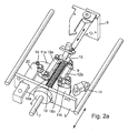
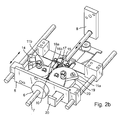
- the structural design of the lancing drive according to the FIGS. 2a and 2 B comprises two flywheels 11a and 11b, which are arranged symmetrically to both sides of the drive rod 7.
- the pressure piece 9 carries a transverse yoke 15, whose two opposite ends are connected by a respective connecting rod 8a and 8b with the flywheels 11a and 11b.
- the flywheels 11a, 11b have at their end faces teeth 16a, 16b, which engage with each other.
- the transverse yoke 15 is pivotally mounted by means of a rotary joint 17. This gives the mechanical system the necessary degree of freedom to run without inhibition even with a possible misalignment of the drive rod 7.
- flywheels 11a, 11b are formed in the manner of simple crankshafts, with a single crank arm and a respective crank pin 18a or 18b on which the crank rods 12a, 12b are mounted like connecting rods.
- left flywheel 11a is provided at the edge of a clamping stop 19.
- a clamping counter-stop 20 which is mounted outside of the sliding carriage 5 stationary in the device housing.
- the flywheel 11a is turned back, wherein the adhesive force between the stop element 13 and counter-stop 14 is overcome. In this way, the compression spring 10 can be tensioned.
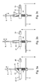
- FIGS. 3a, b and c show an alternative embodiment of the drive mechanism.
- the drive rod 7 carries a pressure piece 9.
- a compression spring 10 presses against the underside of the pressure piece 9 so that the drive rod 7 is driven in the direction of the small arrow to the front.
- the lancing drive sits on a sliding carriage 5, which is relatively slowly displaceable in the direction of the large arrow.
- a cuboid flywheel 21 is displaceably mounted along a straight trajectory 22.
- a coupling rod 23 is rotatably mounted with its lower end on the flywheel 21, precisely in the middle.
- the upper end of the coupling rod 23 is rotatably mounted on the pressure piece 9.
- Flywheel 21 and coupling rod 23 form a passive co-rotating coupling gear, which converts the forward and backward movement of the drive rod 7 in a transverse movement of the flywheel 21 and vice versa.
- the movement path 22 extends transversely to the stitch axis.
- Fig. 3b has the drive rod 7 reaches its reversal point, which corresponds to the maximum penetration depth.
- the coupling rod 23 is vertical.
- the coupling gear is in the dead center.
- the compression spring 10 is deflected maximum.
- the flywheel 21 has maximum speed. Due to its inertial mass, the flywheel 21 continues to move in the direction of the transverse arrow transversely to the stitch axis. In this case, the right end of the flywheel approaches a limiting element which is fixedly mounted on the sliding carriage 5.
- Fig. 3c the fast retreat phase is just completed.
- the compression spring 10 is already compressed again a piece.
- the kinetic energy of the flywheel 21 was applied to the drive rod 7 and the lancet (cf. Fig. 1a ) shifted back.
- the lancing drive was stopped at the end by the flywheel 21 has struck with its right front side of the limiting element 24.
- the flywheel 21 is here made of ferromagnetic iron.
- the limiting element 24 is designed as a permanent magnet whose poles are closed by the flywheel 21, which acts as a magnetic armature. In the end position, therefore, the flywheel 21 and the limiting element 24 are held together by magnetic force. This sets the lancing drive.
- the further embodiment according to the Figures 4a, 4b and 4c differs from the embodiment described above only in that the trajectory 22 of the flywheel body 21 is not transversely, but obliquely with respect to the stitch axis by approximately 15 degrees.
- the coupling rod 23 is not vertical at top dead center, but is inclined by the same angle to the left, as in Fig. 4b to see. Since the center of the flywheel 21, which simultaneously forms the point of articulation for the coupling rod 23, moves downwards on an inclined path, less kinetic energy is required to accelerate the flywheel 21.
Landscapes
- Health & Medical Sciences (AREA)
- Life Sciences & Earth Sciences (AREA)
- Molecular Biology (AREA)
- Surgery (AREA)
- Biophysics (AREA)
- Pathology (AREA)
- Engineering & Computer Science (AREA)
- Biomedical Technology (AREA)
- Heart & Thoracic Surgery (AREA)
- Medical Informatics (AREA)
- Hematology (AREA)
- Physics & Mathematics (AREA)
- Animal Behavior & Ethology (AREA)
- General Health & Medical Sciences (AREA)
- Public Health (AREA)
- Veterinary Medicine (AREA)
- Dermatology (AREA)
- Pain & Pain Management (AREA)
- Measurement Of The Respiration, Hearing Ability, Form, And Blood Characteristics Of Living Organisms (AREA)
- Sampling And Sample Adjustment (AREA)
- Investigating Or Analysing Biological Materials (AREA)
Priority Applications (3)
| Application Number | Priority Date | Filing Date | Title |
|---|---|---|---|
| AT08170441T ATE542478T1 (de) | 2008-12-02 | 2008-12-02 | Gerät zur gewinnung einer blutprobe |
| EP08170441A EP2193746B8 (fr) | 2008-12-02 | 2008-12-02 | Appareil destiné à la production d'un échantillon de sang |
| US12/627,420 US8317813B2 (en) | 2008-12-02 | 2009-11-30 | Device for acquiring a blood sample |
Applications Claiming Priority (1)
| Application Number | Priority Date | Filing Date | Title |
|---|---|---|---|
| EP08170441A EP2193746B8 (fr) | 2008-12-02 | 2008-12-02 | Appareil destiné à la production d'un échantillon de sang |
Publications (3)
| Publication Number | Publication Date |
|---|---|
| EP2193746A1 true EP2193746A1 (fr) | 2010-06-09 |
| EP2193746B1 EP2193746B1 (fr) | 2012-01-25 |
| EP2193746B8 EP2193746B8 (fr) | 2012-03-28 |
Family
ID=40602331
Family Applications (1)
| Application Number | Title | Priority Date | Filing Date |
|---|---|---|---|
| EP08170441A Not-in-force EP2193746B8 (fr) | 2008-12-02 | 2008-12-02 | Appareil destiné à la production d'un échantillon de sang |
Country Status (3)
| Country | Link |
|---|---|
| US (1) | US8317813B2 (fr) |
| EP (1) | EP2193746B8 (fr) |
| AT (1) | ATE542478T1 (fr) |
Families Citing this family (6)
| Publication number | Priority date | Publication date | Assignee | Title |
|---|---|---|---|---|
| SG154343A1 (en) * | 2008-01-08 | 2009-08-28 | Ting Choon Meng | Method and apparatus for intra-articular injection or aspiration |
| US9717452B2 (en) | 2010-12-30 | 2017-08-01 | Roche Diabetes Care, Inc. | Handheld medical diagnostic devices with lancing speed control |
| DE102011015758B4 (de) * | 2011-03-31 | 2013-08-01 | Gerresheimer Regensburg Gmbh | Stechvorrichtung mit Drehelement |
| US9486187B2 (en) * | 2013-09-26 | 2016-11-08 | Covidien Lp | Wind up deployment mechanisms for surgical instruments |
| CN113057846B (zh) * | 2020-09-25 | 2022-08-09 | 江西应用科技学院 | 一种卧式上肢康复理疗方法及装置 |
| CN114947994B (zh) * | 2022-05-24 | 2025-06-20 | 四川大学华西医院 | 一种一次性标本回收器 |
Citations (8)
| Publication number | Priority date | Publication date | Assignee | Title |
|---|---|---|---|---|
| EP0036443B1 (fr) | 1980-03-22 | 1986-03-05 | Roche Diagnostics GmbH | Appareil à inciser pour une prise de sang en vue d'un diagnostic |
| US4924879A (en) | 1988-10-07 | 1990-05-15 | Brien Walter J O | Blood lancet device |
| US6206901B1 (en) | 1999-09-06 | 2001-03-27 | Wlodzimierz Rutynowski | Puncturing device |
| EP1090584A2 (fr) * | 1999-10-09 | 2001-04-11 | Roche Diagnostics GmbH | Dispositif pour le prélèvement du sang par lancette à des fins de diagnostique |
| US20050131441A1 (en) * | 2003-12-16 | 2005-06-16 | Toshiaki Iio | Lancet for blood collection and puncture needle unit |
| WO2007073870A2 (fr) | 2005-12-15 | 2007-07-05 | Roche Diagnostics Gmbh | Système de ponction servant à prélever un échantillon de liquide organique |
| US20070213682A1 (en) * | 2006-03-13 | 2007-09-13 | Hans-Peter Haar | Penetration device, kit, and method |
| EP1852069A1 (fr) | 2006-05-04 | 2007-11-07 | Roche Diagnostics GmbH | Système de prélèvement sanguin d'une partie du corps |
Family Cites Families (9)
| Publication number | Priority date | Publication date | Assignee | Title |
|---|---|---|---|---|
| US623531A (en) * | 1899-04-25 | duncan | ||
| US5035704A (en) * | 1989-03-07 | 1991-07-30 | Lambert Robert D | Blood sampling mechanism |
| JP3097600B2 (ja) | 1997-05-30 | 2000-10-10 | 日本電気株式会社 | 角質層穿刺装置 |
| US5938679A (en) | 1997-10-14 | 1999-08-17 | Hewlett-Packard Company | Apparatus and method for minimally invasive blood sampling |
| US6231531B1 (en) | 1999-04-09 | 2001-05-15 | Agilent Technologies, Inc. | Apparatus and method for minimizing pain perception |
| EP1764037A1 (fr) | 2005-09-15 | 2007-03-21 | F.Hoffmann-La Roche Ag | Dispositif pour l'extraction de liquides corporels aux fins d'analyse |
| US20080019870A1 (en) | 2006-07-21 | 2008-01-24 | Michael John Newman | Integrated medical device dispensing and lancing mechanisms and methods of use |
| US8118824B2 (en) | 2008-09-16 | 2012-02-21 | Roche Diagnostics Operations, Inc. | Magnetic powered lancing drive |
| EP2311373B1 (fr) | 2009-10-15 | 2012-08-01 | Roche Diagnostics GmbH | Système de piqûre pour l'extraction d'un liquide corporel |
-
2008
- 2008-12-02 EP EP08170441A patent/EP2193746B8/fr not_active Not-in-force
- 2008-12-02 AT AT08170441T patent/ATE542478T1/de active
-
2009
- 2009-11-30 US US12/627,420 patent/US8317813B2/en not_active Expired - Fee Related
Patent Citations (8)
| Publication number | Priority date | Publication date | Assignee | Title |
|---|---|---|---|---|
| EP0036443B1 (fr) | 1980-03-22 | 1986-03-05 | Roche Diagnostics GmbH | Appareil à inciser pour une prise de sang en vue d'un diagnostic |
| US4924879A (en) | 1988-10-07 | 1990-05-15 | Brien Walter J O | Blood lancet device |
| US6206901B1 (en) | 1999-09-06 | 2001-03-27 | Wlodzimierz Rutynowski | Puncturing device |
| EP1090584A2 (fr) * | 1999-10-09 | 2001-04-11 | Roche Diagnostics GmbH | Dispositif pour le prélèvement du sang par lancette à des fins de diagnostique |
| US20050131441A1 (en) * | 2003-12-16 | 2005-06-16 | Toshiaki Iio | Lancet for blood collection and puncture needle unit |
| WO2007073870A2 (fr) | 2005-12-15 | 2007-07-05 | Roche Diagnostics Gmbh | Système de ponction servant à prélever un échantillon de liquide organique |
| US20070213682A1 (en) * | 2006-03-13 | 2007-09-13 | Hans-Peter Haar | Penetration device, kit, and method |
| EP1852069A1 (fr) | 2006-05-04 | 2007-11-07 | Roche Diagnostics GmbH | Système de prélèvement sanguin d'une partie du corps |
Also Published As
| Publication number | Publication date |
|---|---|
| ATE542478T1 (de) | 2012-02-15 |
| US20100152759A1 (en) | 2010-06-17 |
| US8317813B2 (en) | 2012-11-27 |
| EP2193746B1 (fr) | 2012-01-25 |
| EP2193746B8 (fr) | 2012-03-28 |
Similar Documents
| Publication | Publication Date | Title |
|---|---|---|
| EP1852069B1 (fr) | Système de prélèvement sanguin d'une partie du corps | |
| DE102004059491B4 (de) | Lanzettenvorrichtung zum Erzeugen einer Einstichwunde und Lanzettenantriebs-Baugruppe | |
| EP2193746B1 (fr) | Appareil destiné à la production d'un échantillon de sang | |
| EP1884191B1 (fr) | Système a piquer la peau | |
| EP1648540B1 (fr) | Dispositif d'injection | |
| DE60317997T2 (de) | Lanzette | |
| EP1631337B1 (fr) | Dispositif d'insertion pour equipement de perfusion | |
| EP2213229B1 (fr) | Système de prise de sang | |
| EP1797822A1 (fr) | Système pour obtenir un échantillon de fluide corporel par perforation de la peau | |
| DE202009003009U1 (de) | Injektionsvorrichtung mit Injektionsvolumeneinstellung | |
| DE102004037270A1 (de) | Blutentnahmesystem zur Entnahme von Blut für Diagnosezwecke | |
| EP3377312B1 (fr) | Presse à course imposée comportant un coulisseau | |
| WO2018011356A1 (fr) | Dispositifd'entraînement d'un élément de meuble mobile, et procédé d'ouverture et de fermeture d'un élément de meuble mobile | |
| EP2429768B1 (fr) | Outil d'enfoncement | |
| EP2925190B1 (fr) | Dispositif pour déplacer un élément mobile de meuble | |
| DE102009025444A1 (de) | Stechhilfe mit Lanzettenauswurfmittel | |
| EP1924200B1 (fr) | Dispositif permettant de recueillir des volumes humoraux a des fins d'analyse | |
| EP2311373B1 (fr) | Système de piqûre pour l'extraction d'un liquide corporel | |
| EP2563223B1 (fr) | Aide à la plantation dotée d'un déclenchement automatique | |
| DE3625695A1 (de) | Verfahren und vorrichtung zur metallspiegel- kryofixation von biologisch-medizinischen oder aehnlichen technischen objekten | |
| DE102013208300A1 (de) | Hebelmechanismus zwischen Vorspanneinrichtung und Schwungrad zum Einwirken auf Stößel eines Setzgeräts | |
| DE102015222995A1 (de) | Weggebundene Presse mit Kulissenstein | |
| DE102004064136B4 (de) | Lanzettenvorrichtung zum Erzeugen einer Einstichwunde | |
| EP4732884A1 (fr) | Module d'aiguille pour un appareil manuel destiné au perçage local d'une peau, appareil manuel et procédé de fonctionnement d'un module d'aiguille | |
| DE2259229A1 (de) | Nadelapparat fuer medizinische zwecke |
Legal Events
| Date | Code | Title | Description |
|---|---|---|---|
| PUAI | Public reference made under article 153(3) epc to a published international application that has entered the european phase |
Free format text: ORIGINAL CODE: 0009012 |
|
| AK | Designated contracting states |
Kind code of ref document: A1 Designated state(s): AT BE BG CH CY CZ DE DK EE ES FI FR GB GR HR HU IE IS IT LI LT LU LV MC MT NL NO PL PT RO SE SI SK TR |
|
| AX | Request for extension of the european patent |
Extension state: AL BA MK RS |
|
| 17P | Request for examination filed |
Effective date: 20100625 |
|
| AKX | Designation fees paid |
Designated state(s): AT BE BG CH CY CZ DE DK EE ES FI FR GB GR HR HU IE IS IT LI LT LU LV MC MT NL NO PL PT RO SE SI SK TR |
|
| GRAP | Despatch of communication of intention to grant a patent |
Free format text: ORIGINAL CODE: EPIDOSNIGR1 |
|
| GRAS | Grant fee paid |
Free format text: ORIGINAL CODE: EPIDOSNIGR3 |
|
| 17Q | First examination report despatched |
Effective date: 20111107 |
|
| GRAA | (expected) grant |
Free format text: ORIGINAL CODE: 0009210 |
|
| AK | Designated contracting states |
Kind code of ref document: B1 Designated state(s): AT BE BG CH CY CZ DE DK EE ES FI FR GB GR HR HU IE IS IT LI LT LU LV MC MT NL NO PL PT RO SE SI SK TR |
|
| REG | Reference to a national code |
Ref country code: GB Ref legal event code: FG4D Free format text: NOT ENGLISH |
|
| REG | Reference to a national code |
Ref country code: CH Ref legal event code: EP |
|
| RAP2 | Party data changed (patent owner data changed or rights of a patent transferred) |
Owner name: F. HOFFMANN-LA ROCHE AG Owner name: ROCHE DIAGNOSTICS GMBH |
|
| REG | Reference to a national code |
Ref country code: AT Ref legal event code: REF Ref document number: 542478 Country of ref document: AT Kind code of ref document: T Effective date: 20120215 |
|
| REG | Reference to a national code |
Ref country code: IE Ref legal event code: FG4D |
|
| REG | Reference to a national code |
Ref country code: DE Ref legal event code: R096 Ref document number: 502008006178 Country of ref document: DE Effective date: 20120322 |
|
| REG | Reference to a national code |
Ref country code: DE Ref legal event code: R081 Ref document number: 502008006178 Country of ref document: DE Owner name: ROCHE DIABETES CARE GMBH, DE Free format text: FORMER OWNERS: ROCHE DIAGNOSTICS GMBH, 68305 MANNHEIM, DE; F. HOFFMANN-LA ROCHE AG, 4070 BASEL, CH |
|
| REG | Reference to a national code |
Ref country code: NL Ref legal event code: VDEP Effective date: 20120125 |
|
| LTIE | Lt: invalidation of european patent or patent extension |
Effective date: 20120125 |
|
| PG25 | Lapsed in a contracting state [announced via postgrant information from national office to epo] |
Ref country code: BG Free format text: LAPSE BECAUSE OF FAILURE TO SUBMIT A TRANSLATION OF THE DESCRIPTION OR TO PAY THE FEE WITHIN THE PRESCRIBED TIME-LIMIT Effective date: 20120425 Ref country code: LT Free format text: LAPSE BECAUSE OF FAILURE TO SUBMIT A TRANSLATION OF THE DESCRIPTION OR TO PAY THE FEE WITHIN THE PRESCRIBED TIME-LIMIT Effective date: 20120125 Ref country code: HR Free format text: LAPSE BECAUSE OF FAILURE TO SUBMIT A TRANSLATION OF THE DESCRIPTION OR TO PAY THE FEE WITHIN THE PRESCRIBED TIME-LIMIT Effective date: 20120125 Ref country code: NL Free format text: LAPSE BECAUSE OF FAILURE TO SUBMIT A TRANSLATION OF THE DESCRIPTION OR TO PAY THE FEE WITHIN THE PRESCRIBED TIME-LIMIT Effective date: 20120125 Ref country code: NO Free format text: LAPSE BECAUSE OF FAILURE TO SUBMIT A TRANSLATION OF THE DESCRIPTION OR TO PAY THE FEE WITHIN THE PRESCRIBED TIME-LIMIT Effective date: 20120425 Ref country code: IS Free format text: LAPSE BECAUSE OF FAILURE TO SUBMIT A TRANSLATION OF THE DESCRIPTION OR TO PAY THE FEE WITHIN THE PRESCRIBED TIME-LIMIT Effective date: 20120525 |
|
| REG | Reference to a national code |
Ref country code: IE Ref legal event code: FD4D |
|
| PG25 | Lapsed in a contracting state [announced via postgrant information from national office to epo] |
Ref country code: PT Free format text: LAPSE BECAUSE OF FAILURE TO SUBMIT A TRANSLATION OF THE DESCRIPTION OR TO PAY THE FEE WITHIN THE PRESCRIBED TIME-LIMIT Effective date: 20120525 Ref country code: LV Free format text: LAPSE BECAUSE OF FAILURE TO SUBMIT A TRANSLATION OF THE DESCRIPTION OR TO PAY THE FEE WITHIN THE PRESCRIBED TIME-LIMIT Effective date: 20120125 Ref country code: PL Free format text: LAPSE BECAUSE OF FAILURE TO SUBMIT A TRANSLATION OF THE DESCRIPTION OR TO PAY THE FEE WITHIN THE PRESCRIBED TIME-LIMIT Effective date: 20120125 Ref country code: FI Free format text: LAPSE BECAUSE OF FAILURE TO SUBMIT A TRANSLATION OF THE DESCRIPTION OR TO PAY THE FEE WITHIN THE PRESCRIBED TIME-LIMIT Effective date: 20120125 Ref country code: GR Free format text: LAPSE BECAUSE OF FAILURE TO SUBMIT A TRANSLATION OF THE DESCRIPTION OR TO PAY THE FEE WITHIN THE PRESCRIBED TIME-LIMIT Effective date: 20120426 |
|
| PG25 | Lapsed in a contracting state [announced via postgrant information from national office to epo] |
Ref country code: CY Free format text: LAPSE BECAUSE OF FAILURE TO SUBMIT A TRANSLATION OF THE DESCRIPTION OR TO PAY THE FEE WITHIN THE PRESCRIBED TIME-LIMIT Effective date: 20120125 |
|
| PG25 | Lapsed in a contracting state [announced via postgrant information from national office to epo] |
Ref country code: EE Free format text: LAPSE BECAUSE OF FAILURE TO SUBMIT A TRANSLATION OF THE DESCRIPTION OR TO PAY THE FEE WITHIN THE PRESCRIBED TIME-LIMIT Effective date: 20120125 Ref country code: SE Free format text: LAPSE BECAUSE OF FAILURE TO SUBMIT A TRANSLATION OF THE DESCRIPTION OR TO PAY THE FEE WITHIN THE PRESCRIBED TIME-LIMIT Effective date: 20120125 Ref country code: CZ Free format text: LAPSE BECAUSE OF FAILURE TO SUBMIT A TRANSLATION OF THE DESCRIPTION OR TO PAY THE FEE WITHIN THE PRESCRIBED TIME-LIMIT Effective date: 20120125 Ref country code: IE Free format text: LAPSE BECAUSE OF FAILURE TO SUBMIT A TRANSLATION OF THE DESCRIPTION OR TO PAY THE FEE WITHIN THE PRESCRIBED TIME-LIMIT Effective date: 20120125 Ref country code: DK Free format text: LAPSE BECAUSE OF FAILURE TO SUBMIT A TRANSLATION OF THE DESCRIPTION OR TO PAY THE FEE WITHIN THE PRESCRIBED TIME-LIMIT Effective date: 20120125 Ref country code: RO Free format text: LAPSE BECAUSE OF FAILURE TO SUBMIT A TRANSLATION OF THE DESCRIPTION OR TO PAY THE FEE WITHIN THE PRESCRIBED TIME-LIMIT Effective date: 20120125 Ref country code: SI Free format text: LAPSE BECAUSE OF FAILURE TO SUBMIT A TRANSLATION OF THE DESCRIPTION OR TO PAY THE FEE WITHIN THE PRESCRIBED TIME-LIMIT Effective date: 20120125 |
|
| PG25 | Lapsed in a contracting state [announced via postgrant information from national office to epo] |
Ref country code: IT Free format text: LAPSE BECAUSE OF FAILURE TO SUBMIT A TRANSLATION OF THE DESCRIPTION OR TO PAY THE FEE WITHIN THE PRESCRIBED TIME-LIMIT Effective date: 20120125 Ref country code: SK Free format text: LAPSE BECAUSE OF FAILURE TO SUBMIT A TRANSLATION OF THE DESCRIPTION OR TO PAY THE FEE WITHIN THE PRESCRIBED TIME-LIMIT Effective date: 20120125 |
|
| PLBE | No opposition filed within time limit |
Free format text: ORIGINAL CODE: 0009261 |
|
| STAA | Information on the status of an ep patent application or granted ep patent |
Free format text: STATUS: NO OPPOSITION FILED WITHIN TIME LIMIT |
|
| 26N | No opposition filed |
Effective date: 20121026 |
|
| REG | Reference to a national code |
Ref country code: DE Ref legal event code: R097 Ref document number: 502008006178 Country of ref document: DE Effective date: 20121026 |
|
| PG25 | Lapsed in a contracting state [announced via postgrant information from national office to epo] |
Ref country code: ES Free format text: LAPSE BECAUSE OF FAILURE TO SUBMIT A TRANSLATION OF THE DESCRIPTION OR TO PAY THE FEE WITHIN THE PRESCRIBED TIME-LIMIT Effective date: 20120506 |
|
| BERE | Be: lapsed |
Owner name: F. HOFFMANN-LA ROCHE A.G. Effective date: 20121231 |
|
| PG25 | Lapsed in a contracting state [announced via postgrant information from national office to epo] |
Ref country code: MC Free format text: LAPSE BECAUSE OF NON-PAYMENT OF DUE FEES Effective date: 20121231 |
|
| REG | Reference to a national code |
Ref country code: CH Ref legal event code: PL |
|
| GBPC | Gb: european patent ceased through non-payment of renewal fee |
Effective date: 20121202 |
|
| REG | Reference to a national code |
Ref country code: FR Ref legal event code: ST Effective date: 20130830 |
|
| PG25 | Lapsed in a contracting state [announced via postgrant information from national office to epo] |
Ref country code: BE Free format text: LAPSE BECAUSE OF NON-PAYMENT OF DUE FEES Effective date: 20121231 |
|
| PG25 | Lapsed in a contracting state [announced via postgrant information from national office to epo] |
Ref country code: LI Free format text: LAPSE BECAUSE OF NON-PAYMENT OF DUE FEES Effective date: 20121231 Ref country code: CH Free format text: LAPSE BECAUSE OF NON-PAYMENT OF DUE FEES Effective date: 20121231 |
|
| PG25 | Lapsed in a contracting state [announced via postgrant information from national office to epo] |
Ref country code: MT Free format text: LAPSE BECAUSE OF FAILURE TO SUBMIT A TRANSLATION OF THE DESCRIPTION OR TO PAY THE FEE WITHIN THE PRESCRIBED TIME-LIMIT Effective date: 20120125 Ref country code: GB Free format text: LAPSE BECAUSE OF NON-PAYMENT OF DUE FEES Effective date: 20121202 Ref country code: FR Free format text: LAPSE BECAUSE OF NON-PAYMENT OF DUE FEES Effective date: 20130102 |
|
| PG25 | Lapsed in a contracting state [announced via postgrant information from national office to epo] |
Ref country code: TR Free format text: LAPSE BECAUSE OF FAILURE TO SUBMIT A TRANSLATION OF THE DESCRIPTION OR TO PAY THE FEE WITHIN THE PRESCRIBED TIME-LIMIT Effective date: 20120125 |
|
| PG25 | Lapsed in a contracting state [announced via postgrant information from national office to epo] |
Ref country code: LU Free format text: LAPSE BECAUSE OF NON-PAYMENT OF DUE FEES Effective date: 20121202 |
|
| PG25 | Lapsed in a contracting state [announced via postgrant information from national office to epo] |
Ref country code: HU Free format text: LAPSE BECAUSE OF FAILURE TO SUBMIT A TRANSLATION OF THE DESCRIPTION OR TO PAY THE FEE WITHIN THE PRESCRIBED TIME-LIMIT Effective date: 20081202 |
|
| REG | Reference to a national code |
Ref country code: AT Ref legal event code: MM01 Ref document number: 542478 Country of ref document: AT Kind code of ref document: T Effective date: 20131202 |
|
| PG25 | Lapsed in a contracting state [announced via postgrant information from national office to epo] |
Ref country code: AT Free format text: LAPSE BECAUSE OF NON-PAYMENT OF DUE FEES Effective date: 20131202 |
|
| REG | Reference to a national code |
Ref country code: DE Ref legal event code: R081 Ref document number: 502008006178 Country of ref document: DE Owner name: ROCHE DIABETES CARE GMBH, DE Free format text: FORMER OWNER: ROCHE DIAGNOSTICS GMBH, 68305 MANNHEIM, DE |
|
| PGFP | Annual fee paid to national office [announced via postgrant information from national office to epo] |
Ref country code: DE Payment date: 20201112 Year of fee payment: 13 |
|
| REG | Reference to a national code |
Ref country code: DE Ref legal event code: R119 Ref document number: 502008006178 Country of ref document: DE |
|
| PG25 | Lapsed in a contracting state [announced via postgrant information from national office to epo] |
Ref country code: DE Free format text: LAPSE BECAUSE OF NON-PAYMENT OF DUE FEES Effective date: 20220701 |