EP2193864A1 - System zur herstellung einer legierung - Google Patents
System zur herstellung einer legierung Download PDFInfo
- Publication number
- EP2193864A1 EP2193864A1 EP08833241A EP08833241A EP2193864A1 EP 2193864 A1 EP2193864 A1 EP 2193864A1 EP 08833241 A EP08833241 A EP 08833241A EP 08833241 A EP08833241 A EP 08833241A EP 2193864 A1 EP2193864 A1 EP 2193864A1
- Authority
- EP
- European Patent Office
- Prior art keywords
- heat
- alloy
- retaining
- container
- producing
- Prior art date
- Legal status (The legal status is an assumption and is not a legal conclusion. Google has not performed a legal analysis and makes no representation as to the accuracy of the status listed.)
- Withdrawn
Links
Images
Classifications
-
- H—ELECTRICITY
- H01—ELECTRIC ELEMENTS
- H01F—MAGNETS; INDUCTANCES; TRANSFORMERS; SELECTION OF MATERIALS FOR THEIR MAGNETIC PROPERTIES
- H01F1/00—Magnets or magnetic bodies characterised by the magnetic materials therefor; Selection of materials for their magnetic properties
- H01F1/01—Magnets or magnetic bodies characterised by the magnetic materials therefor; Selection of materials for their magnetic properties of inorganic materials
- H01F1/03—Magnets or magnetic bodies characterised by the magnetic materials therefor; Selection of materials for their magnetic properties of inorganic materials characterised by their coercivity
- H01F1/032—Magnets or magnetic bodies characterised by the magnetic materials therefor; Selection of materials for their magnetic properties of inorganic materials characterised by their coercivity of hard-magnetic materials
- H01F1/04—Magnets or magnetic bodies characterised by the magnetic materials therefor; Selection of materials for their magnetic properties of inorganic materials characterised by their coercivity of hard-magnetic materials metals or alloys
- H01F1/047—Alloys characterised by their composition
- H01F1/053—Alloys characterised by their composition containing rare earth metals
- H01F1/055—Alloys characterised by their composition containing rare earth metals and magnetic transition metals, e.g. SmCo5
- H01F1/057—Alloys characterised by their composition containing rare earth metals and magnetic transition metals, e.g. SmCo5 and IIIa elements, e.g. Nd2Fe14B
- H01F1/0571—Alloys characterised by their composition containing rare earth metals and magnetic transition metals, e.g. SmCo5 and IIIa elements, e.g. Nd2Fe14B in the form of particles, e.g. rapid quenched powders or ribbon flakes
- H01F1/0575—Alloys characterised by their composition containing rare earth metals and magnetic transition metals, e.g. SmCo5 and IIIa elements, e.g. Nd2Fe14B in the form of particles, e.g. rapid quenched powders or ribbon flakes pressed, sintered or bonded together
- H01F1/0577—Alloys characterised by their composition containing rare earth metals and magnetic transition metals, e.g. SmCo5 and IIIa elements, e.g. Nd2Fe14B in the form of particles, e.g. rapid quenched powders or ribbon flakes pressed, sintered or bonded together sintered
-
- B—PERFORMING OPERATIONS; TRANSPORTING
- B22—CASTING; POWDER METALLURGY
- B22D—CASTING OF METALS; CASTING OF OTHER SUBSTANCES BY THE SAME PROCESSES OR DEVICES
- B22D11/00—Continuous casting of metals, i.e. casting in indefinite lengths
- B22D11/06—Continuous casting of metals, i.e. casting in indefinite lengths into moulds with travelling walls, e.g. with rolls, plates, belts, caterpillars
- B22D11/0611—Continuous casting of metals, i.e. casting in indefinite lengths into moulds with travelling walls, e.g. with rolls, plates, belts, caterpillars formed by a single casting wheel, e.g. for casting amorphous metal strips or wires
-
- B—PERFORMING OPERATIONS; TRANSPORTING
- B22—CASTING; POWDER METALLURGY
- B22D—CASTING OF METALS; CASTING OF OTHER SUBSTANCES BY THE SAME PROCESSES OR DEVICES
- B22D11/00—Continuous casting of metals, i.e. casting in indefinite lengths
- B22D11/12—Accessories for subsequent treating or working cast stock in situ
- B22D11/126—Accessories for subsequent treating or working cast stock in situ for cutting
-
- B—PERFORMING OPERATIONS; TRANSPORTING
- B22—CASTING; POWDER METALLURGY
- B22F—WORKING METALLIC POWDER; MANUFACTURE OF ARTICLES FROM METALLIC POWDER; MAKING METALLIC POWDER; APPARATUS OR DEVICES SPECIALLY ADAPTED FOR METALLIC POWDER
- B22F1/00—Metallic powder; Treatment of metallic powder, e.g. to facilitate working or to improve properties
- B22F1/06—Metallic powder characterised by the shape of the particles
- B22F1/068—Flake-like particles
-
- B—PERFORMING OPERATIONS; TRANSPORTING
- B22—CASTING; POWDER METALLURGY
- B22F—WORKING METALLIC POWDER; MANUFACTURE OF ARTICLES FROM METALLIC POWDER; MAKING METALLIC POWDER; APPARATUS OR DEVICES SPECIALLY ADAPTED FOR METALLIC POWDER
- B22F1/00—Metallic powder; Treatment of metallic powder, e.g. to facilitate working or to improve properties
- B22F1/14—Treatment of metallic powder
- B22F1/142—Thermal or thermo-mechanical treatment
-
- C—CHEMISTRY; METALLURGY
- C22—METALLURGY; FERROUS OR NON-FERROUS ALLOYS; TREATMENT OF ALLOYS OR NON-FERROUS METALS
- C22C—ALLOYS
- C22C33/00—Making ferrous alloys
- C22C33/02—Making ferrous alloys by powder metallurgy
-
- H—ELECTRICITY
- H01—ELECTRIC ELEMENTS
- H01F—MAGNETS; INDUCTANCES; TRANSFORMERS; SELECTION OF MATERIALS FOR THEIR MAGNETIC PROPERTIES
- H01F41/00—Apparatus or processes specially adapted for manufacturing or assembling magnets, inductances or transformers; Apparatus or processes specially adapted for manufacturing materials characterised by their magnetic properties
- H01F41/02—Apparatus or processes specially adapted for manufacturing or assembling magnets, inductances or transformers; Apparatus or processes specially adapted for manufacturing materials characterised by their magnetic properties for manufacturing cores, coils, or magnets
- H01F41/0253—Apparatus or processes specially adapted for manufacturing or assembling magnets, inductances or transformers; Apparatus or processes specially adapted for manufacturing materials characterised by their magnetic properties for manufacturing cores, coils, or magnets for manufacturing permanent magnets
- H01F41/0266—Moulding; Pressing
-
- B—PERFORMING OPERATIONS; TRANSPORTING
- B22—CASTING; POWDER METALLURGY
- B22F—WORKING METALLIC POWDER; MANUFACTURE OF ARTICLES FROM METALLIC POWDER; MAKING METALLIC POWDER; APPARATUS OR DEVICES SPECIALLY ADAPTED FOR METALLIC POWDER
- B22F9/00—Making metallic powder or suspensions thereof
- B22F9/02—Making metallic powder or suspensions thereof using physical processes
- B22F9/04—Making metallic powder or suspensions thereof using physical processes starting from solid material, e.g. by crushing, grinding or milling
- B22F2009/048—Making metallic powder or suspensions thereof using physical processes starting from solid material, e.g. by crushing, grinding or milling by pulverising a quenched ribbon
-
- C—CHEMISTRY; METALLURGY
- C22—METALLURGY; FERROUS OR NON-FERROUS ALLOYS; TREATMENT OF ALLOYS OR NON-FERROUS METALS
- C22C—ALLOYS
- C22C2202/00—Physical properties
- C22C2202/02—Magnetic
Definitions
- the present invention relates to an apparatus for producing an alloy.
- the present invention relates to an apparatus for producing a R-T-B-based rare-element containing alloy (R is at least one element of the rare-earth elements containing Y, T is metal which contains essentially Fe, and B is boron).
- R is at least one element of the rare-earth elements containing Y
- T is metal which contains essentially Fe
- B is boron
- R-T-B-based magnets which have the maximum magnetic energy product in permanent magnets, are used for HD (hard disks), MRI (magnetic resonance imaging methods), various motors, etc. because they have high characteristics.
- HD hard disks
- MRI magnetic resonance imaging methods
- various motors etc. because they have high characteristics.
- the use of R-T-B magnets as motors including a motor for vehicles has increased. Since the main components of the R-T-B-based magnets are Nd, Fe, and B, the R-T-B magnets are also collectively called Nd-Fe-B magnets.
- R means Nd, a part of which is replaced with at least one rare-earth element, such as Pr, Dy, and Tb, in particular, often Nd, a part of which is replaced with at least one of rare-earth elements including Y.
- T means an alloy of Fe as an essential component, and Co, Ni, etc.
- B is boron, and may be partially substituted with C or N.
- Other elements such as Cu, Al, Ti, V, Cr, Ga, Mn, Nb, Ta, Mo, W, Ca, Sn, Zr, and Hf may be added to the R-T-B-based alloys, singly or in combination of two or more species.
- R-T-B-based alloys which are R-T-B magnets, contain a ferromagnetic phase, R 2 T 14 B crystals, which contribute to magnetization, as the main phase, and a nonmagnetic R-rich phase having a low melting point and containing a non-magnetic rare-earth element at high concentration. Since the R-T-B-based alloy is an active metallic material, the alloy is generally melted and cast in a vacuum or under an inert gas.
- a sintered magnet is obtained from casting a R-T-B-based alloy ingot by a powder metallurgy method, in general, an alloy ingot is crushed to obtain alloy powder having a particle size of about 3 ⁇ m (as measured by means of FSSS (Fisher Sub-Sieve Sizer)), the powder is subjected to pressing in a magnetic field, the obtained compact is sintered in a sintering furnace at about 1,000 to 1,100°C, the sintered product is heated, mechanically processed, and plated for corrosion prevention, and a sintered magnet is obtained.
- FSSS Fisher Sub-Sieve Sizer
- the R-rich phase plays the following important roles in the R-T-B-based sintered magnet.
- ⁇ -Fe is formed in the cast alloy.
- the ⁇ -Fe has deformability, and remains in a crusher, without being crushed. Due to this, ⁇ -Fe not only deteriorates crushing efficiency during the crushing of the alloy, but also changes the composition before and after crushing, and greatly affects the particle distribution. In addition, if ⁇ -Fe remains even after sintering, magnetic characteristics of the sintered product are deteriorated.
- a strip casting method in which an alloy ingot is cast with a higher cooling rate has been developed, and employed in actual production steps.
- SC method an alloy is rapidly solidified by pouring a molten alloy onto a rotating copper roller, the inside of which is cooled by water, to cast a strip having a thickness of about 0.1 to about 1 mm.
- the molten alloy is supercooled to the formation temperature of R 2 T 14 B or less, which is the main phase. Therefore, it is possible to form directly R 2 T 14 B from the molten alloy. Due to this, it is possible to prevent the formation of ⁇ -Fe.
- the alloy flakes which are cast by the SC method, have superior uniformity of microstructure.
- the uniformity in microstructure can be evaluated based on a crystal grain size and the dispersion state of the R-rich phase.
- chill crystals sometimes generate on a side which contacts with a cast roller (abbreviated as "cast surface side” below). Therefore, it is possible to obtain a reasonably fine and uniform microstructure by rapid solidification.
- the R-T-B-based alloy obtained by the SC method has a finely dispersed R-rich phase, and the formation of ⁇ -Fe is also prevented. Therefore, when a sintered magnet is obtained, uniformity of the R-rich phase in the final magnet product is improved, and crushing and adverse effects due to ⁇ -Fe can be prevented. In this way, the R-T-B-based alloy ingot obtained by the SC method has superior microstructure for producing sintered magnets.
- Patent Document No. 1 Japanese Unexamined Patent Application, First Publication No. H5-222488
- the R-T-B-based alloys obtained by the SC method are further improved.
- the R-T-B-based alloy contains mainly R, T, and B (boron), where R denotes Nd, a part of which is replaced with at least one of rare-earth elements including Y.
- T means an alloy containing Fe as an essential component, and Co, Ni, etc.
- heat resistance of the R-T-B-based alloy is determined depending on coercive force.
- the compositional ratio of Dy and Tb in the R-T-B-based alloys becomes higher, coercive force also increases.
- Dy or Tb is added in alloys, coercive force increases, but remanence tends to be decreased. Therefore, it is difficult to satisfy demands by customers by only increasing the compositional ratio of Dy and Tb.
- an object of the present invention to provide an apparatus for producing an alloy containing a rare-earth element, which can produce a rare-earth magnet having high coercive force, and decrease Br (remanence) due to addition of Dy and Tb minimum.
- the present invention provides the following inventions.
- the apparatus for producing an alloy according to [6] wherein a plurality of the heat-retaining containers is fixed to the endless conveyor belt.
- the rare-earth element containing alloy is an R-T-B-based alloy (wherein R is at least one element selected from the group consisting of rare-earth elements including Y, T is an alloy containing Fe as an essential component, and B is boron).
- R is at least one element selected from the group consisting of rare-earth elements including Y
- T is an alloy containing Fe as an essential component
- B is boron
- the apparatus for producing an alloy according to any one of [1] to [11], wherein the alloy is a hydrogen storage alloy.
- the apparatus for producing an alloy according to the present invention includes a heat-retaining container for storing the cast alloy flakes supplied from the crushing device, a temperature retaining heater for maintaining the temperature of the cast alloy flakes in the heat-retaining container, and an inclination device for sending the cast alloy flakes in the heat-retaining container to the storage container by inclining the heat-retaining container. Therefore, it is possible to improve various properties of the obtained alloy by retaining the temperature of the cast alloy flakes after crushing. In particular, when the alloy is the R-T-B-based alloy, the coercive force can be improved by retaining the temperature. Therefore, it is possible to produce a rare-earth element magnet having high coercive force without increasing the compositional ratio of Dy and Tb in the R-T-B-based alloy.
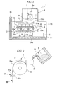
- FIG. 1 is a schematic elevation view showing one embodiment of the apparatus for producing an alloy of the present invention.
- the production apparatus 1 for an alloy (abbreviated as "production apparatus” below) shown in FIG 1 includes mainly a casting device 2 for casting the molten alloy, a crushing device 21 for crushing a cast alloy after casting, a heat-retaining device 3 for maintaining the temperature of cast alloy flakes after crushing, and a storage container 5 for storing the cast alloy flakes after maintaining the temperature.
- the production apparatus 1 shown in FIG. 1 is stored in a chamber 6.
- the inside of the chamber 6 is in an inert gas atmosphere under reduced pressure.
- As the inert gas for example, argon is used.
- the chamber 6 there are a casting chamber 6a, and a heat-retaining and storing chamber 6b, which is arranged below the casting chamber 6a and connected with the casting chamber 6a.
- the casting chamber 6a In the casting chamber 6a, the casting device 2 and the crushing device 21 are stored.
- the heat-retaining and storing chamber 6b the heat-retaining device 3 is stored. In this way, the heat-retaining device 3 is arranged below the crushing device 21.
- the container 5 is arranged below the heat-retaining device 3.
- the container 5 is made of various metals, which can be used under high temperatures, such as stainless, iron, HASTELLOY®, and INCONEL®.
- the production apparatus 1 is provided with a belt conveyor 51 (movable device), which moves the container 5.
- the container 5 can move in the horizontal direction in FIG 1 by being arranged on the belt conveyor 51.
- the heat-retaining and storing chamber 6b has a gate 6e.
- the heat-retaining and storing chamber 6b is hermetically closed by the gate 6e except when the container 5 is transferred outside the heat-retaining and storing chamber 6b.
- a cooling chamber may be provided to the heat-retaining and storing chamber 6b on the opposite side of the gate 6e. Furthermore, it possible to provide another gate in the cooling chamber to transfer the container 5 to the outside of the chamber 6.
- FIG 2 is a schematic view showing the casting device 2 and the crushing device 21 in the production apparatus 1.
- the casting device 2 shown in FIG. 2 casts a molten alloy by the SC method.
- the crushing device 21 crushes the cast alloy to form cast alloy flakes.
- reference number 22 denotes a cooling roller having a diameter in a range of from about 60 to 80 mm for rapidly cooling the molten alloy L and casting to obtain a cast alloy M.
- Reference number 23 denotes a tundish for supplying the molten alloy L onto the cooling roller 22.
- the cast alloy M obtained by the cooling roller 22 is crushed by the crushing device 21 to form the cast alloy flakes N.
- the molten alloy L is produced in a high frequency melting furnace (not shown in Figures) which is outside of the chamber 6.
- a molten metal is prepared by putting raw materials into a refractory crucible 24 under a vacuum or an inert gas atmosphere, and making molten the raw materials by a high frequency melting process.
- the temperature of the molten metal L varies depending on the composition of the alloy, it is adjusted to a range of from 1300°C to 1500°C.
- the prepared molten metal L is transferred to the casting device 2, together with the refractory crucible 24. Then, the molten alloy L is supplied from the refractory crucible 24 into the tundish 23.
- the tundish 23 has a rectifier device or a slag removal device, if necessary.
- the cooling roller 22 has a water cooling device, which is not shown in figures, inside thereof.
- the circumference 22a of the cooling roller 22 is cooled by the water cooling device.
- the material constituting the cooling roller 22 is preferably copper or a copper alloy, because it has high thermal conductivity and is easily obtainable.
- the supply rate of the molten alloy L and the revolution speed of the cooling roller 22 are controlled according to the thickness of the casting alloy M.
- the surface speed of the cooling roller 22 is preferably in a range of from 0.5 to 3 m/s of the rotating speed, since an alloy easily adheres to the peripheral surface 22a of the cooling roller 22, depending on the construction material of the cooling roller 22, or the surface state of the peripheral surface 22a. Therefore, when a cleaning device is installed depending on necessity, the quality of the cast R-T-B-based alloy is stabilized.
- the cast alloy M solidified on the cooling roller 22 falls off the cooling roller 22 on the opposite side of the tundish 23.
- the crushing device 21 has a pair of crushing rollers 21a.
- the cast alloy M is applied between two crushing rollers 21 a and 21a, the cast alloy M is crushed to form cast alloy flakes N.
- the cast alloy flakes N fall, and are sent to the heat-retaining device 3, as shown in FIG. 1 .
- the heat-retaining device 3 has a plural heat-retaining containers 32, a temperature retaining heater, which maintains the temperature of the heat-retaining container 32 and the cast alloy flakes N in the heat-retaining container 32, and a belt conveyor (inclination device) 33.
- the heat-retaining container 32 stores the cast alloy flakes N which have fallen from the crushing device 21.
- the heat-retaining container 32 is made of a material having high thermal insulation properties, for example, a ceramic block, such as alumina block and zirconia block, a fibrous plate, or a complex material in which plural metal thin plates are deposited with a gap.
- the belt conveyor 33 makes the heat-retaining container 32 incline to send out the cast alloy flakes N in the heat-retaining container 32 into the container 5.
- the belt conveyor 33 has plural conveyor rollers 34 which extend in a substantially horizontal direction, an endless ring-shaped conveyor belt 35 which is installed on the periphery of the plural conveyor rollers 34, and a fixing member 36 for fixing the heat-retaining container 32 on the conveyor surface of the endless conveyor belt 35 so as to swing.
- the plural conveyor rollers 34 include a pair of end rollers 34a and 34a which are arranged on both sides, and intermediate rollers 34b which are arranged between the end rollers 34a and 34a.
- the belt conveyor 33 makes the heat-retaining container 32 incline while the transfer direction of the endless conveyor belt 35 is reversed by one end roller 34a.
- the heat-retaining container 32 is fixed on the exterior surface of the endless conveyor belt 35 such that the opening portion 32 faces outwardly.
- the heat-retaining container 32 circles on the outside of the endless conveyor belt 35, while the opening portion 32 faces outwardly, by rotating the conveyor rollers 34.
- the cast alloy flakes N are supplied from the crushing device 21 to the heat-retaining container 32 having the open portion 32 facing outwardly during moving.
- the heat-retaining container 32 is made to incline at the end portion 33a of the belt conveyor 33 in the transfer direction, the cast alloy flakes N in the heat-retaining container 32 are sent to the container 5.
- the temperature retaining heater in the heat-retaining device 3 shown in FIG. 1 has an upper heater 31 a, and a lower heater 31 b.
- the upper heater 31 a is arranged above the heat-retaining container 32.
- the upper heater 31a heats the moving heat-retaining container 32 while the opening portion 32a faces upwardly, from above.
- the lower heater 31b is arranged below the heat-retaining container 32.
- the lower heater 31b heats the moving heat-retaining container 32 while the opening portion 32a faces downwardly, from the bottom.
- a flake injection hole 31c for supplying the cast alloy flakes N from the crushing device 21 to the heat-retaining container 32 is formed in a part of the upper heater 31 a. As shown in FIG. 1 , the flake injection hole 31c is arranged below the crushing device 21.
- the heating manner of the upper and lower heaters 31 a and 31 b is not particularly limited. For example, resistance heating, infrared-ray heating, and induction heating are used. In addition, since a heating element in the upper and lower heaters 31a and 31b may be a metal wire, silicon carbide, black lead, etc. can be used.
- the upper heater 31a is arranged such that the flake injection hole 31c of the upper heater 31 a is positioned below the crushing device 21.
- the container 5 is arranged so as to store the cast alloy flakes N from the moving heat-retaining container 32 at the end portion 33a of the belt conveyor 33 in the transfer direction.
- the heat-retaining container is rotated by operating the belt conveyor 33.
- the temperature of the heat-retaining container is raised to a fixed temperature by switching on the upper and lower heaters 31a and 31b.
- the cast alloy flakes N are produced by operating the crushing device 21.
- a molten alloy L is prepared using a melting device not shown in figures.
- the molten metal L in the refractory crucible 24 is supplied to the tundish 23.
- the molten metal L is supplied onto the cooling roller 22 from the tundish 23, and the molten metal is solidified to make the cast alloy M.
- the cast alloy flakes N are obtained by removing the cast alloy M from the cooling roller 22, and crushing between the crushing rolls 21a.
- the molten metal L has a composition expressed by a general formula, R-T-B.
- R denotes at least one of rare-earth elements including Y.
- T means Fe which is partially replaced with a metal, such as Co, and Ni.
- B is boron, or boron which is partially replaced with C or N.
- other elements such as Cu, Al, Ti, V, Cr, Ga Mn, Nb, Ta, Mo, W, Ca, Sn, Zr, and Hf may be added, to the R-T-B-based alloys, singly or in combination of two or more species.
- the composition ratio of R is 28 to 33% by mass, B is 0.9 to 1.3% by mass, and T is the remainder.
- composition of the molten metal L used in the production apparatus 1 is not limited to the above ranges. Any composition can be used as long as it is a R-T-B-based alloy.
- the average cooling rate of the molten alloy on the cooling roller be adjusted to a range of from 300 to 3000°C per second.
- the cooling rate is sufficient, and the precipitation of ⁇ -Fe, and coarsening of the R 2 T 17 phase can be more reliably prevented.
- supercooling is not excessive, and it is possible to supply the cast alloy flakes to the heat-retaining device 3 maintaining more adequate temperatures.
- the cast alloy flakes are not cooled more than necessary. Therefore, reheating of the cast alloy flakes is not necessary.
- an average cooling rate is calculated by dividing the temperature difference of the molten alloy between just before contacting the cooling roller 22 and when removing from the cooling roller 22 by the period of time during contacting with the cooling roller 22.
- the average temperature of the cast alloy M when removing from the cooling roller 22 varies depending on slight variation of contacting conditions between the cast alloy M and the cooling roller 22, or the thickness of the cast alloy M.
- the average temperature of the cast alloy M when removing from the cooling roller 22 is obtained by averaging the measurement values obtained by measuring the surface of the alloy in the width direction throughout the casting using a radiation thermometer. It is preferable that the average temperature of the cast alloy M when removing from the cooling roller 22 be a temperature which is 100°C to 500°C less than the solidification temperature of the molten alloy when the R 2 T 14 B phase is in equilibrium, and a temperature which is 100°C to 400°C less than the solidification temperature is more preferable.
- the melting point is 1,150°C. This melting point varies by replacing Nd with another rare-earth element, Fe with another transition element, or kind and amount of another additive element added.
- the difference between the average temperature of the cast alloy M when removing from the cooling roller 22 and the solidification temperature of the cast alloy M when the R 2 T 14 B phase is in equilibrium is less than 100°C, the cooling rate is insufficient. In contrast, when the difference is 500°C or more, the cooling rate is too fast.
- the molten alloy is supercooled, the conditions of the alloy are not uniform within the alloy, and vary depending on the contact degree between the molten alloy L and the cooling roller 22, or the distance from the contacting portion on the cooling roller 22.
- the cast alloy flakes N which are crushed by the crushing device 21, fall and pass through the flake injection hole 31c, and then are stored in the heat-retaining container 32 below the crushing device 21.
- the temperature of the heat-retaining container 32 is adjusted to a fixed temperature by the upper heater 31a and the lower heater 31b.
- the cast alloy flakes N are continuously supplied to the heat-retaining container 32 from the crushing device 21 with a predetermined supply amount. Since the heat-retaining containers 32 are rotated by the belt conveyor 33 in the heat-retaining device 3, the cast alloy flakes N supplied from the crushing device 21 are in series put into the heat-retaining containers 32 which are heated by the upper and lower heaters 31 a and 31 b. After maintaining the temperature during a predetermined time, the cast alloy flakes N are sent to the container 5.
- each heat-retaining container 32 is explained.
- the temperature of the empty heat-retaining container 32, of which the opening portion 32a faces upwardly, is maintained at predetermined temperatures by heating with the upper heater 31a while moving from the left-hand side to right-hand side in FIG. 1 by the belt conveyor 33.
- the heat-retaining container 32 with a predetermined temperature reaches a position below the flake injection hole 31 of the upper heater 31a, the cast alloy flakes N are supplied from the crushing device 21 to the heat-retaining container 32. Then, the temperature of the cast alloy flakes N starts be maintained. After that, the heat-retaining container 32 containing the cast alloy flakes N moves further from the left-hand side to right-hand side in FIG.
- the heat-retaining container 32 which reaches the end portion 33a of the belt conveyor 33 turns over. Due to this, the direction of the opening portion 32a of the heat-retaining container 32 changes from upwardly to downwardly.
- the cast alloy flakes N in the heat-retaining container 32 are sent to the container 5 by the inclination and reversing of the heat-retaining container 32. Then, maintaining the temperature of the cast alloy flakes N is finished.
- the period of time after the cast alloy flakes N are stored in the heat-retaining container 32 before the cast alloy flakes N are sent to the container 5 is adjusted by controlling the moving speed of the heat-retaining container 32 by the belt conveyor 33 in the heat-retaining device 3 shown in FIG. 1 .
- the temperature of the empty heat-retaining container 32 of which the opening portion 32a faces downwardly is maintained at specific temperatures by heating with the lower heater 31b while moving from the right-hand side to left-hand side in FIG. 1 by the belt conveyor 33.
- the heat-retaining container 32 which reaches the opposite end in the transfer direction of the belt conveyor 33, inclines and turns over. Thereby, the direction of the opening portion 32a of the heat-retaining container 32 changes from downwardly to upwardly. Then, the heat-retaining container 32 is heated by the upper heater 31 a again, and starts to move from the left-hand side to right-hand side in FIG. 1 by the belt conveyor 33.
- the temperature of the heat-retaining container 32 that is, the maintaining temperature of the cast alloy flakes, be less than the temperature of the cast alloy flakes N when moving from the cooling roller 22 (abbreviated as "cooling roller removing temperature” below).
- the temperature is preferably in a range of from (cooling roller removing temperature - 100°C) to the cooling roller removing temperature, and more preferably in a range of from (cooling roller removing temperature - 50°C) to the cooling roller removing temperature. More specifically, it is preferably in a range of from 600°C to 900°C.
- the temperature of the cast alloy flakes N is maintained in the range, it is possible to improve the coercive force of the R-T-B-based alloy.
- the maintaining temperature is 600°C or more, the coercive force can be further improved.
- it is less than 900°C it is possible to prevent more reliably the formation of ⁇ -Fe, and coarsening of the R 2 T 17 phase.
- the temperature of the cast alloy flakes N is maintained at 1,000°C or more, the coercive force is also improved.
- the cast alloy flakes N are maintained at 1,000°C, the microstructure becomes coarse. Therefore, the grain size distribution, fluidity, and sintering temperature after crushation vary. Due to this, it is necessary to consider the effects after maintaining the temperature in a case of maintaining the cast alloy flakes N at 1,000°C.
- the cooling roll removing temperature falls for a any reason, it is possible to raise and maintain the temperature of the cast alloy flakes N by controlling the upper heater 31a and/or the lower heater 31b, and making the maintaining temperature higher than the cooling roller removing temperature. Thereby, the temperature of the cast alloy flakes N can be raised and maintained.
- the raising temperature range is preferably 100°C or less, and more preferably 50°C or less. When the raising temperature range is larger than 100°C, productivity may be decreased.
- the heat-retaining time of the cast alloy flakes N is preferably 30 seconds or more, more preferably in a range of from 30 seconds to several hours, and most preferably in a range of from 30 seconds to 2 minutes.
- the heat-retaining time is 30 seconds or more, the coercive force can be further improved. It is possible to maintain for several hours. However, in terms of the productivity, 2 minutes or less is preferable.
- the cast alloy flakes N which are sent to the container 5 after maintaining the temperature thereof by the heat-retaining device 3, are collected in the container 5 uniformly in the horizontal direction, because the container 5 moves in the horizontal direction in FIG 1 by the belt conveyor 51.
- the cast alloy flakes N collected in the container 5 are cooled by contacting the inner wall of the container 5.
- the cast alloy flakes N in the container 5 are transferred outside of the chamber 6 by opening the gate 6e of the heat-retaining and storing chamber 6b, and transferring the container 5 to the outside of the chamber 6.
- the cooling chamber is formed in the chamber 6, the cast alloy flakes N in the container 5 are cooled by opening the gate 6e of the heat-retaining and storing chamber 6b, and transferring the container 5 to the cooling chamber.
- the gate of the cooling chamber is opened, and the container 5 is transferred outside of the chamber 6.
- the production apparatus shown in FIG 1 has the heat-retaining device 3, which includes the heat-retaining container 32 for storing the cast alloy flakes N supplied from the crushing device, a temperature retaining heater for maintaining the temperature of the cast alloy flakes N in the heat-retaining container 32, and the belt conveyor 33 for sending the cast alloy flakes N in the heat-retaining container 32 to the container 5 by inclining the heat-retaining container 32. Therefore, it is possible to maintain the temperature of the cast alloy flakes N containing the R-T-B-based alloy after crushing.
- the cast alloy flakes N which are a raw material of the rare-earth magnet having high coercive force and high thermal resistance without increasing the compositional ratio of Dy and Tb in the R-T-B-based alloy.
- the belt conveyor 33 sends the cast alloy flakes N into the container 5. Therefore, it is possible to further improve the coercive force of the cast alloy flakes N.
- the belt conveyor 33 in the production apparatus shown in FIG. 1 has the endless conveyor belt 35, which rotates and is installed on the periphery of the conveyor rollers 34, and a fixing member 36 which fixes the heat-retaining container 32 on the surface of the endless conveyor belt 35 so as to swing.
- the belt conveyor 33 makes the heat-retaining container 32 incline when the transfer direction of the endless conveyor belt 34 is reversed by the roller 34a at one end.
- the time after the cast alloy flakes N are stored in the heat-retaining container 32 before the cast alloy flakes N are sent to the container 5, that is, heat-retaining time, can be controlled by adjusting the moving speed of the heat-retaining container 32 by the belt conveyor 33.
- the heat-retaining container 32 rotates by the belt conveyor 33 in the heat-retaining device 3 shown in FIG 1 .
- the cast alloy flakes N supplied from the crushing device 21 are successively stored in the heat-retaining containers 32. Due to this, the cast alloy flakes N do not exist at one place in the heat-retaining container 32. That is, it is possible to store uniformly the cast alloy flakes N in the heat-retaining container 32. Thereby, it is possible to maintain uniformly the temperature of the cast alloy flakes N in the heat-retaining container 32, and the cast alloy flakes N having uniform quality can be obtained.
- the heat-retaining device 3 has the upper heater 31a for heating the heat-retaining container 32 having the open portion 32 facing upwardly while moving.
- the flake injection hole 31 is formed at a part of the upper heater 31 a.
- the flake injection hole 31 is below the crushing device 21. Due to this, the cast alloy flakes N can be supplied from the crushing device 21 into the heat-retaining container 32 having the opening portion 32a facing upwardly while moving. At the same time, the heat-retaining container 32 having the opening portion 32a facing upwardly can be heated from the upper portion.
- the heat-retaining device 3 is arranged below the crushing device 21, the cast alloy flakes N can be supplied from the crushing device to the heat-retaining device 3 by only making the cast alloy flakes N fall. Therefore, it is not necessary to use a transfer mechanism for transferring the cast alloy flakes N from the crushing device 21 to the heat-retaining device 3.
- the size of the production apparatus 1 can be reduced, and space for the production apparatus 1 can also be reduced.
- the heat-retaining device 3 has the lower heater 32b for heating the heat-retaining container 32 having the opening portion 32a facing downwardly from the lower portion.
- the heat-retaining container 32 having the opening portion 32a facing downwardly can be heated at specific temperatures. Thereby, the temperature of the heat-retaining container 32 when the cast alloy flakes N are supplied to the heat-retaining container 32 can be easily adjusted to the specific temperature range.
- the belt conveyor 51 which makes the container 5 move Since it has the belt conveyor 51 which makes the container 5 move, the cast alloy flakes N after maintaining the temperature can be collected uniformly in the container 5 by moving the container 5 with the belt conveyor 51. Thereby, it is possible to obtain the cast alloy flakes N having uniform quality. In addition, it has the belt conveyor 51 which makes the container 5 move freely, the cast alloy flakes N after maintaining the temperature can be easily transferred out of the production apparatus 1.
- the casting device 2 since the casting device 2 has the crushing device 21, the cast alloy ingot is promptly crushed to make the cast alloy flakes N. Thereby, the cast alloy can be easily handled in the container 5 and the heat-retaining device 3.
- the casting device 2 and heat-retaining device 3 are arranged in the chamber 6 in an inert gas atmosphere, deterioration of R-T-B-based alloy can be prevented.
- the cooling chamber since the container 5 can move into the cooling chamber, it is possible to transfer the cast alloy flakes N after maintaining the temperature together with the container 5 out of the heat-retaining and storing chamber 6b to cool them. Thereby, it is possible to improve the productivity.
- the rare-earth element containing alloy is the R-T-B-based alloy
- the coercive force of the R-T-B-based alloy containing the rare-earth element containing alloy increases, when the compositional ratio of Dy and increases.
- the remanence tends to decrease. Since the production apparatus 1 has the heat-retaining device 3, the temperature of the R-T-B-based alloy can be maintained. Thereby, the coercive force of the magnet containing the R-T-B-based alloy can also be improved. Therefore, it is possible to decrease the compositional ratio of Dy and Tb. In addition, the remanence can be also improved by decreasing the compositional ratio of Dy and Tb.
- the heat-retaining device 3 is not limited to this embodiment.
- the heat-retaining device 3 has the upper and lower heaters 31 a and 31b shown in FIG 1 , the maintaining temperature can be easily controlled exactly. Therefore, such a structure is preferable.
- the heat insulation efficiency of the heat-retaining container 32 is sufficiently high, and the cast alloy flakes N in the heat-retaining container 32 can be kept at sufficiently high temperature for sufficient time, only either one of the upper and lower heaters 31a and 31b can be used.
- a heater it is also possible for a heater to be fixed on the side wall and/or the bottom of the heat-retaining container 32, instead of or in addition to the upper and lower heaters 31a and 31b. In this case, it is possible to exactly control the maintaining temperature of the cast alloy flakes N.
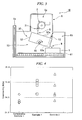
- the heat-retaining device 3 may have the structure shown in FIG. 3 . Similar to the heat-retaining device 3 shown in FIG 1 , the heat-retaining device 30 shown in FIG. 3 has a heat-retaining container 52 for storing the cast alloy flakes N supplied from the crushing device 21, a temperature retaining heater (not shown in FIG. 3 ), which maintains the temperature of the heat-retaining container 52 and the cast alloy flakes N in the heat-retaining container 52, and an inclination device 13 for inclining the heat-retaining container 52 to send the cast alloy flakes N in the heat-retaining container 52 into the container 5.
- a temperature retaining heater not shown in FIG. 3
- an inclination device 13 for inclining the heat-retaining container 52 to send the cast alloy flakes N in the heat-retaining container 52 into the container 5.
- the inclination device 13 has a rotation shaft 55 provided with the heat-retaining container 52, and a movable device (not shown in FIG. 3 ) for rotating the rotational shaft 55 to incline and rotate the heat-retaining container 52.
- the heat-retaining container 52 is supported while an opening portion 52a faces outwardly so as to be able to rotate by the rotation shaft 55 which extends in the substantially horizontal direction.
- the inclination and rotation of the heat-retaining container 52 are controlled by the movable device.
- the heat-retaining container 52 has the opening portion 52a at the upper portion.
- the cast alloy flakes N are supplied into the heat-retaining container 52 through the opening portion 52a.
- the heat-retaining container 52 has an outlet portion 53a on one side wall (side portion), and a gate plate 53 which can move in the vertical direction so as to open or close the outlet portion 53a.
- the movement of the gate plate 53 in the vertical direction can be controlled by a moving device (not shown in FIG. 3 ).
- the cast alloy flakes N are supplied from the crushing device 21 into the heat-retaining container 52 through the opening portion 52a. Then, the gate plate 53 provided with the heat-retaining container 52 moves upwardly, and thereby the outlet portion 53 which has been closed by the gate plate 53 is opened.
- the heat-retaining container 52 inclines and rotates by the movable device, the cast alloy flakes N are sent to the container 5 through the outlet portion 53a.
- the inclination and rotation of the heat-retaining container 52 is controlled by the movable device, and the movement of the gate plate 53 is controlled by the transfer device, it is possible to control the maintaining time after the cast alloy flakes N are stored in the heat-retaining container 52 before the cast alloy flakes N are sent to the container 5.
- the heat-retaining device 30 shown in FIG. 3 is made of a material having high thermal insulation properties, for example, a ceramic block, such as alumina block and zirconia block, a fibrous plate, or a complex material in which plural metal thin plates are deposited with a gap.
- the heat-retaining device 30 is preferably made of a complex material in which a heat-resistant board containing fibrous ceramics is inserted between metal plates such as iron plates.
- a heater (not shown in FIG 3 .) is provided on the side wall and/or bottom of the heat-retaining container 52. Heating manner of the heater is not particularly limited.
- a heat generator such as a metal wire, silicon carbide, black lead, etc. can be heated by any one heating manner of resistance heating, infrared-ray heating, and induction heating.
- the cast alloy flakes N are produced using the production apparatus 10 shown in FIG 3 , the cast alloy flakes N fallen from the crushing device 21 are stored in the heat-retaining container 52 below the crushing device 21. Thereby, the temperature of the cast alloy flakes N starts to be maintained. At this time, the temperature of the heat-retaining container 52 is adjusted to a specific temperature by the heater. The outlet portion 53a is closed by the gate plate 53. The heat-retaining container 52 storing the cast alloy flakes N is swung, within an angle range such that the cast alloy flakes N are not spilled, by the movable device, while the opening portion 52a faces upwardly. Thereby the cast alloy flakes N move in the heat-retaining container 52 and are stored uniformly. The cast alloy flakes N can be uniformly heated.
- the outlet portion 52 is formed on the side wall by moving the gate plate 52 by the movable device.
- the heat-retaining container 52 is inclined and rotated by the movable device.
- the cast alloy flakes N in the heat-retaining container 52 are sent to the container 5 through the outlet portion 53, and the maintaining temperature of the cast alloy flakes N is finished.
- the cast alloy flakes N after maintaining the temperature are collected in the container 5, similar to the production apparatus 1 shown in FIG. 1 .
- the heat-retaining time for the cast alloy flakes N is preferably 30 seconds or more, more preferably in a range of from 2 minutes to several hours, and most preferably in a range of from 2 minutes seconds to 30 minutes.
- the heat-retaining time is 2 minutes or more, the coercive force can be further improved. It is possible to maintain for several hours. However, when the productivity is concerned, 30 minutes or less is preferable.
- the production apparatus 10 shown in FIG 3 has the heat-retaining device 30, which includes the heat-retaining container 52 for storing the cast alloy flakes N supplied from the crushing device 21, the heater for maintaining the temperature of the cast alloy flakes N in the heat-retaining container 52, and the inclination device 13 for making the heat-retaining container 52 incline to send the cast alloy flakes N in the heat-retaining container 52 into the container 5. Therefore, similar to the production apparatus shown in 1, it is possible to keep the temperature of the cast alloy flakes N made of the R-T-B-based alloy after casting and crushing.
- the production apparatus 10 shown in FIG 3 has the inclination device 13 for sending the cast alloy flakes N into the container 5 after a fixed heat-retaining time passes since the cast alloy flakes N are stored in the heat-retaining container 52. Therefore, it is possible to further improve the coercive force of the cast alloy flakes N.
- the inclination device 13 Since the inclination device 13 has the rotation shaft 55 provided with the heat-retaining container 52, and the movable device for rotating the rotational shaft 55 to incline and rotate the heat-retaining container 52. Therefore, the cast alloy flakes N, which are supplied from the crushing device 21, are stored in the heat-retaining container 52, and the cast alloy flakes N in the heat-retaining container 52 can be sent to the container 5 by inclining and rotating the heat-retaining container 52. At this time, it is possible to control the heat-retaining time of the cast alloy flakes N by controlling the inclination and rotation of the heat-retaining container 52. Therefore, it is also possible to maintain constantly the heat-retaining time of the cast alloy flakes N and make the quality of the cast alloy flakes N uniform.
- the cast alloy flakes N in the heat-retaining container 52 can be sent to the container 5 by controlling the movement of the gate plate 53 and the rotation of the heat-retaining container 52. Therefore, it is possible to make the rotation angle of the heat-retaining container 52, when the cast alloy flakes N are sent, smaller, compared with a case in which the heat-retaining container 52 does not have the openable outlet portion 53 on the side wall, and the cast alloy flakes N are sent from the opening portion 52a formed upper portion of the heat-retaining container 52. Thereby, size of the production apparatus 10 can be reduced, and space for the production apparatus 10 can also be reduced.
- the heat-retaining container 52 is rotatably supported such that the opening portion 52a faces outwardly by the rotational shaft 55 which extends in the substantially horizontal. Therefore, it is possible to swing the heat-retaining container 52 having the opening portion 52a facing upwardly within an angle range such that the cast alloy flakes N are not spilled, while maintaining the temperature of the cast alloy flakes N in the heat-retaining container 52. Thereby, the cast alloy flakes N can be stored uniformly in the heat-retaining container 52, and the temperature of the cast alloy flakes N in the heat-retaining container 52 can be uniformly kept. Therefore, the cast alloy flakes N having a uniform quality can be produced.
- the upper and lower heaters 31a and 31b in the production apparatus 1 shown in FIG. 1 , instead of or in addition to the heater on the side wall and/or the bottom of the heat-retaining container 32. In this case, it is possible to exactly control the maintaining temperature of the cast alloy flakes N.
- the production apparatus for an alloy of the present invention is not limited to the above embodiments.
- the constitution of the production apparatus according to the present invention can be changed as long as the change of the constitution is within the scope of the present invention.
- the belt conveyor 51 is used as the movable device for moving freely the storage container, it is also possible to use a self-propelled storage container having a carriage with tires. Of course, it is also possible to set rails and make the carriage move along the rails.
- a hopper for introducing the cast alloy flakes N above the heat-retaining container may be provided between the crushing device and the heat-retaining and storing device. In this case, it is possible to prevent scattering of the cast alloy flakes N into the heat-retaining and storing device, when the cast alloy flakes N are sent from the crushing device into the heat retaining device.
- thermoelectric semiconductor alloy can include alloys, which are shown by the general formula A 3-x B x C (in the general formula, A and B denote at least one element selected from the transition metals, such as Fe, Co, Ni, Ti, V, Cr, Zr, Hf, Nb, Mo, Ta, and W, C denotes at least one element selected from the elements in 13rd and 14th groups, such as Al, Ga, In, Si, and Ge).
- alloys can be used, which are shown by the general formula ABC (in the general formula, A and B denote at least one element selected from the transition metals, such as Fe, Co, Ni, Ti, V, Cr, Zr, Hf, Nb, Mo, Ta, and W, C denotes at least one element selected from the elements in 13rd and 14th groups, such as Al, Ga, In, Si, and Ge).
- a and B denote at least one element selected from the transition metals, such as Fe, Co, Ni, Ti, V, Cr, Zr, Hf, Nb, Mo, Ta, and W
- C denotes at least one element selected from the elements in 13rd and 14th groups, such as Al, Ga, In, Si, and Ge).
- rare-earth elements containing alloys can also be used, which are shown by the general formula RE x (Fe 1- yM y ) 4 Sb 12 (in the general formula, RE means at least one of La and Ce, M denotes at least one element selected from the group consisting of Ti, Zr, Sn, and Pb, and x and y satisfy the relationship of 0 ⁇ x ⁇ 1, and 0 ⁇ y ⁇ 1).
- rare-earth elements containing alloys can also be used, which are shown by the general formula RE x (Co 1-y M y ) 4 Sb 12 (in the general formula, RE means at least one of La and Ce, M denotes at least one element selected from the group consisting of Ti, Zr, Sn, Cu, Zn, Mn and Pb, and x and y satisfy the relationship of 0 ⁇ x ⁇ 1, and 0 ⁇ y ⁇ 1).
- AB 2 type alloy alloy containing a transition element, such as titanium, manganese, zirconium, and nickel, as a base
- AB 5 type alloy alloys containing a rare-earth element, niobium, and the zirconium, and at least one transition element having catalyst functions, such as nickel, cobalt, aluminum, etc. with a ratio of 1:5)
- nickel, cobalt, aluminum, etc. with a ratio of 1:5 can be used as the hydrogen-storing metal alloy.
- the cast alloy flakes containing the R-T-B-based alloy are finely pulverized such that the average particle diameter is in a range of from 3 to 5 ⁇ m (measured by a laser diffraction meter), the obtained powder is compacted using a molding device in a transverse magnetic field, and then this is sintered under vacuum conditions. Since the rare-earth element containing magnet in this embodiment contains the R-T-B-based alloy produced by the production apparatus according to the present invention, the coercive force is high and magnetic properties are also excellent.
- metal neodymium, metal dysprosium, ferroboron, cobalt, aluminum, copper, and iron were added to an aluminum crucible so that the raw material contained 28% ofNd, 4.5% of Dy, 0.96% of B, 1.0% of Co, 0.15% of Al, 0.10% of Cu, and the remainder of Fe as a mass ratio, and these were melted in a high frequency melting furnace in an argon gas atmosphere at 1 atom to prepare a molten alloy. Subsequently, the molten alloy was supplied to the production apparatus shown in FIG 1 , and casted by the SC method, and the cast alloy flakes were produced.
- the diameter of the cooling roller was 600 mm
- the material constituting the cooling roller was an alloy containing a small amount of Cr and Zr, and Cu as the remainder.
- the inside of the cooling roller was cooled.
- the rotating speed of the cooling roller during casting was 1.3 m/s.
- the average temperature of the cast alloy when it was removed from the cooling roller was measured using a radiation thermometer, the average temperature was 890°C.
- the difference between the highest temperature and the lowest temperature was 35°C.
- the melting point of the R 2 T 14 B phase in the obtained alloy was about 1,170°C. Therefore, the difference between the average removing temperature and the melting point was about 280°C.
- the average cooling rate of the cast alloy on the cooling roller was 980°C/s, and the average thickness of the cast alloy was 0.29 mm.
- the obtained cast alloy flakes were stored in the heat-retaining container 32 of the heat-retaining device 3 shown in FIG. 1 , and the temperature was maintained at 800°C for 30 seconds on average. In this way, the cast alloy flakes containing the rare-earth element were produced in Example 1.
- Example 2 The cast alloy flakes of Example 2 were produced in a manner identical to that of Example 1, except that the cast alloy flakes were stored in the heat-retaining container 52 of the heat-retaining device 30 shown in FIG 3 , and the temperature was maintained at 800°C for 2 minutes and 30 seconds on average.
- the cast alloy flakes of Comparative Example 1 were produced in a manner identical to that of Example 1, except that the heat-retaining treatment was not carried out.
- the cast alloy flakes in Examples 1 and 2, and Comparative Example 1 were finely pulverized such that the average particle diameter was 5 ⁇ m (measured by a laser diffraction meter), and compacted using the molding device in a transverse magnetic field in a 100% nitrogen atmosphere.
- the molding pressure was 0.8 t/cm 2
- the magnetic field in the cavity of the mold was set to 15 kOe.
- the obtained mold was maintained at 500°C for 1 hour under a vacuum of 1.33x10 -5 hPa, and subsequently this was maintained at 800°C for 2 hours under a vacuum of 1.33x10 -5 hPa.
- FIG. 4 is a graph showing the coercive force (Hcj) of the R-T-B-based magnets of Example 1, Example 2, and Comparative Example 1. It is clear from FIG. 4 that the R-T-B-based magnets of Examples 1 and 2 in which the heat-retaining treatment was performed have a larger coercive force than that of the R-T-B-based magnet of Comparative Example 1 in which the heat-retaining treatment was not performed.
- the production apparatus for an alloy according to the present invention can improve various properties of an alloy.
- the alloy is the R-T-B-based alloy
- the coercive force can be improved by retaining the temperature. Therefore, it is possible to produce a rare-earth element magnet having a high coercive force without increasing the compositional ratio of Dy and Tb in the R-T-B-based alloy.
Landscapes
- Engineering & Computer Science (AREA)
- Chemical & Material Sciences (AREA)
- Mechanical Engineering (AREA)
- Power Engineering (AREA)
- Crystallography & Structural Chemistry (AREA)
- Metallurgy (AREA)
- Manufacturing & Machinery (AREA)
- Thermal Sciences (AREA)
- Physics & Mathematics (AREA)
- Inorganic Chemistry (AREA)
- Materials Engineering (AREA)
- Nanotechnology (AREA)
- Organic Chemistry (AREA)
- Manufacture Of Metal Powder And Suspensions Thereof (AREA)
- Manufacturing Cores, Coils, And Magnets (AREA)
- Hard Magnetic Materials (AREA)
- Continuous Casting (AREA)
- Powder Metallurgy (AREA)
Applications Claiming Priority (2)
| Application Number | Priority Date | Filing Date | Title |
|---|---|---|---|
| JP2007247851A JP4219390B1 (ja) | 2007-09-25 | 2007-09-25 | 合金の製造装置 |
| PCT/JP2008/066827 WO2009041338A1 (ja) | 2007-09-25 | 2008-09-18 | 合金の製造装置 |
Publications (2)
| Publication Number | Publication Date |
|---|---|
| EP2193864A1 true EP2193864A1 (de) | 2010-06-09 |
| EP2193864A4 EP2193864A4 (de) | 2014-07-02 |
Family
ID=40403861
Family Applications (1)
| Application Number | Title | Priority Date | Filing Date |
|---|---|---|---|
| EP08833241.6A Withdrawn EP2193864A4 (de) | 2007-09-25 | 2008-09-18 | System zur herstellung einer legierung |
Country Status (5)
| Country | Link |
|---|---|
| US (1) | US8042600B2 (de) |
| EP (1) | EP2193864A4 (de) |
| JP (1) | JP4219390B1 (de) |
| CN (1) | CN101808769B (de) |
| WO (1) | WO2009041338A1 (de) |
Cited By (1)
| Publication number | Priority date | Publication date | Assignee | Title |
|---|---|---|---|---|
| EP2589445A4 (de) * | 2010-07-02 | 2016-10-05 | Santoku Corp | Verfahren zur herstellung einer legierten bramme für seltenerd-sintermagneten |
Families Citing this family (9)
| Publication number | Priority date | Publication date | Assignee | Title |
|---|---|---|---|---|
| KR101004166B1 (ko) * | 2006-04-07 | 2010-12-24 | 쇼와 덴코 가부시키가이샤 | 합금 및 희토류 원소 합금 제조 장치 |
| JP5750915B2 (ja) * | 2011-01-31 | 2015-07-22 | 日立金属株式会社 | 希土類系磁石用原料合金の水素粉砕粉の製造方法及び製造装置 |
| CN103805825B (zh) * | 2012-11-08 | 2016-04-06 | 沈阳中北真空科技有限公司 | 稀土永磁合金真空感应熔炼速凝设备 |
| KR102310445B1 (ko) * | 2014-11-11 | 2021-10-12 | 일진전기 주식회사 | 독립제어 챔버형 급랭 응고 장치 |
| KR102334640B1 (ko) * | 2014-11-11 | 2021-12-07 | 일진전기 주식회사 | 연속식 급랭 응고 장치 |
| AU2016253743B2 (en) * | 2015-04-30 | 2018-12-20 | Ihi Corporation | Rare earth permanent magnet and method for producing rare earth permanent magnet |
| CN107262688B (zh) * | 2016-04-08 | 2019-04-02 | 沈阳中北真空技术有限公司 | 一种带二次冷却的真空熔炼速凝设备及速凝合金制造方法 |
| CN108907208A (zh) * | 2018-07-21 | 2018-11-30 | 芜湖君华材料有限公司 | 一种非晶合金磁性粉末生产系统 |
| CN110280744A (zh) * | 2019-06-24 | 2019-09-27 | 宁夏森源重工设备有限公司 | 铁合金辊模浇注装置 |
Family Cites Families (16)
| Publication number | Priority date | Publication date | Assignee | Title |
|---|---|---|---|---|
| JPS6347301A (ja) * | 1986-08-15 | 1988-02-29 | Matsushita Electric Works Ltd | 永久磁石粉末の製法 |
| JP2639609B2 (ja) | 1992-02-15 | 1997-08-13 | 三徳金属工業株式会社 | 永久磁石用合金鋳塊及びその製造法 |
| DE69318998T2 (de) | 1992-02-15 | 1998-10-15 | Santoku Metal Ind | Legierungsblock für einen Dauermagnet, anisotropes Pulver für einen Dauermagnet, Verfahren zur Herstellung eines solchen und Dauermagneten |
| JP3201944B2 (ja) * | 1995-12-04 | 2001-08-27 | 株式会社三徳 | 希土類金属含有合金の製造システム |
| JP3909557B2 (ja) * | 1996-07-03 | 2007-04-25 | ヤマハ株式会社 | 熱電材料及びその製造方法 |
| US6043424A (en) | 1996-07-03 | 2000-03-28 | Yamaha Corporation | Thermoelectric alloy achieving large figure of merit by reducing oxide and process of manufacturing thereof |
| JP2000225460A (ja) * | 1999-02-05 | 2000-08-15 | Shin Etsu Chem Co Ltd | 希土類含有合金又は水素吸蔵合金の製造装置および製造方法 |
| JP2001226753A (ja) * | 2000-02-10 | 2001-08-21 | Sumitomo Special Metals Co Ltd | 鉄基合金軟磁性材料およびその製造方法 |
| CN100345987C (zh) * | 2001-03-12 | 2007-10-31 | 昭和电工株式会社 | 控制含稀土元素的合金结构的方法、该合金的粉末材料和使用该合金粉末材料的磁体 |
| JP3561692B2 (ja) * | 2001-03-12 | 2004-09-02 | 昭和電工株式会社 | 希土類元素含有合金の組織制御方法、同合金粉末及びそれを用いた磁石 |
| JP3628282B2 (ja) * | 2001-07-03 | 2005-03-09 | 独立行政法人科学技術振興機構 | 希土類酸化物の還元による極低酸素含有量でかつ微細で均質な結晶組織の希土類系合金の製造方法 |
| JP4479944B2 (ja) * | 2001-12-18 | 2010-06-09 | 昭和電工株式会社 | 希土類磁石用合金薄片およびその製造方法 |
| AU2002358316A1 (en) | 2001-12-18 | 2003-06-30 | Showa Denko K.K. | Alloy flake for rare earth magnet, production method thereof, alloy powder for rare earth sintered magnet, rare earth sintered magnet, alloy powder for bonded magnet and bonded magnet |
| WO2005105343A1 (ja) * | 2004-04-30 | 2005-11-10 | Neomax Co., Ltd. | 希土類磁石用原料合金および粉末ならびに焼結磁石の製造方法 |
| JP2007064490A (ja) * | 2005-08-29 | 2007-03-15 | Jfe Steel Kk | 金属粉末用ベルト式熱処理炉の雰囲気ガスシール装置及び雰囲気ガスシール方法 |
| KR101004166B1 (ko) * | 2006-04-07 | 2010-12-24 | 쇼와 덴코 가부시키가이샤 | 합금 및 희토류 원소 합금 제조 장치 |
-
2007
- 2007-09-25 JP JP2007247851A patent/JP4219390B1/ja not_active Expired - Fee Related
-
2008
- 2008-09-18 US US12/678,218 patent/US8042600B2/en not_active Expired - Fee Related
- 2008-09-18 CN CN2008801082980A patent/CN101808769B/zh not_active Expired - Fee Related
- 2008-09-18 EP EP08833241.6A patent/EP2193864A4/de not_active Withdrawn
- 2008-09-18 WO PCT/JP2008/066827 patent/WO2009041338A1/ja not_active Ceased
Cited By (2)
| Publication number | Priority date | Publication date | Assignee | Title |
|---|---|---|---|---|
| EP2589445A4 (de) * | 2010-07-02 | 2016-10-05 | Santoku Corp | Verfahren zur herstellung einer legierten bramme für seltenerd-sintermagneten |
| US9862030B2 (en) | 2010-07-02 | 2018-01-09 | Santoku Corporation | Method for producing alloy cast slab for rare earth sintered magnet |
Also Published As
| Publication number | Publication date |
|---|---|
| US20100202917A1 (en) | 2010-08-12 |
| CN101808769A (zh) | 2010-08-18 |
| JP4219390B1 (ja) | 2009-02-04 |
| WO2009041338A1 (ja) | 2009-04-02 |
| JP2009079241A (ja) | 2009-04-16 |
| CN101808769B (zh) | 2013-07-10 |
| EP2193864A4 (de) | 2014-07-02 |
| US8042600B2 (en) | 2011-10-25 |
Similar Documents
| Publication | Publication Date | Title |
|---|---|---|
| US8042600B2 (en) | Apparatus for producing alloy | |
| US8961868B2 (en) | Nanocomposite bulk magnet and process for producing same | |
| KR101036968B1 (ko) | R-t-b계 합금 및 그 제조 방법, r-t-b계 희토류 영구자석용 미분말 및 r-t-b계 희토류 영구 자석 | |
| RU2401878C2 (ru) | Сплав системы r-t-b и способ получения сплава системы r-t-b, тонкий порошок для редкоземельного постоянного магнита системы r-t-b, а также редкоземельный постоянный магнит системы r-t-b | |
| CN103875046B (zh) | R-t-b系合金薄片、r-t-b系烧结磁体及其制造方法 | |
| US20100230013A1 (en) | R-t-b alloy, process for production of r-t-b alloy, fine powder for r-t-b rare earth permanent magnets, and r-t-b rare earth permanent magnet | |
| CN101356030B (zh) | 用于生产合金的设备以及稀土元素合金 | |
| JP3845461B2 (ja) | ボンド磁石用永久磁石合金粉末の製造方法及びその装置 | |
| US7431070B2 (en) | Rare earth magnet alloy ingot, manufacturing method for the same, R-T-B type magnet alloy ingot, R-T-B type magnet, R-T-B type bonded magnet, R-T-B type exchange spring magnet alloy ingot, R-T-B type exchange spring magnet, and R-T-B type exchange spring bonded magnet | |
| JP4329318B2 (ja) | 希土類焼結磁石およびその製造方法 | |
| TWI437103B (zh) | 生產合金的設備 | |
| JP4000620B2 (ja) | 永久磁石合金粉末の製造方法 | |
| JP5344296B2 (ja) | タンディッシュとそれを用いたr−t−b系合金の製造方法 | |
| JP2003293097A (ja) | ナノコンポジット磁石用急冷合金およびその製造方法 | |
| JP2001288546A (ja) | 鉄基合金磁石およびその製造方法 |
Legal Events
| Date | Code | Title | Description |
|---|---|---|---|
| PUAI | Public reference made under article 153(3) epc to a published international application that has entered the european phase |
Free format text: ORIGINAL CODE: 0009012 |
|
| 17P | Request for examination filed |
Effective date: 20100331 |
|
| AK | Designated contracting states |
Kind code of ref document: A1 Designated state(s): AT BE BG CH CY CZ DE DK EE ES FI FR GB GR HR HU IE IS IT LI LT LU LV MC MT NL NO PL PT RO SE SI SK TR |
|
| AX | Request for extension of the european patent |
Extension state: AL BA MK RS |
|
| DAX | Request for extension of the european patent (deleted) | ||
| A4 | Supplementary search report drawn up and despatched |
Effective date: 20140603 |
|
| RIC1 | Information provided on ipc code assigned before grant |
Ipc: H01F 41/02 20060101ALI20140527BHEP Ipc: C22C 33/02 20060101ALI20140527BHEP Ipc: B22F 9/04 20060101AFI20140527BHEP |
|
| STAA | Information on the status of an ep patent application or granted ep patent |
Free format text: STATUS: THE APPLICATION IS DEEMED TO BE WITHDRAWN |
|
| 18D | Application deemed to be withdrawn |
Effective date: 20150106 |