EP2193907A1 - Schnecken-Maschine mit axialem Ausgleich für thermische Ausdehnung - Google Patents
Schnecken-Maschine mit axialem Ausgleich für thermische Ausdehnung Download PDFInfo
- Publication number
- EP2193907A1 EP2193907A1 EP08021246A EP08021246A EP2193907A1 EP 2193907 A1 EP2193907 A1 EP 2193907A1 EP 08021246 A EP08021246 A EP 08021246A EP 08021246 A EP08021246 A EP 08021246A EP 2193907 A1 EP2193907 A1 EP 2193907A1
- Authority
- EP
- European Patent Office
- Prior art keywords
- housing
- screw
- worm
- longitudinal axis
- machine according
- Prior art date
- Legal status (The legal status is an assumption and is not a legal conclusion. Google has not performed a legal analysis and makes no representation as to the accuracy of the status listed.)
- Granted
Links
- 230000005540 biological transmission Effects 0.000 claims description 5
- 230000007246 mechanism Effects 0.000 claims description 2
- 238000004519 manufacturing process Methods 0.000 description 3
- 230000008878 coupling Effects 0.000 description 2
- 238000010168 coupling process Methods 0.000 description 2
- 238000005859 coupling reaction Methods 0.000 description 2
- 230000007704 transition Effects 0.000 description 2
- XRWSZZJLZRKHHD-WVWIJVSJSA-N asunaprevir Chemical compound O=C([C@@H]1C[C@H](CN1C(=O)[C@@H](NC(=O)OC(C)(C)C)C(C)(C)C)OC1=NC=C(C2=CC=C(Cl)C=C21)OC)N[C@]1(C(=O)NS(=O)(=O)C2CC2)C[C@H]1C=C XRWSZZJLZRKHHD-WVWIJVSJSA-N 0.000 description 1
- 229940125961 compound 24 Drugs 0.000 description 1
- 238000007872 degassing Methods 0.000 description 1
- 230000001419 dependent effect Effects 0.000 description 1
- 238000010438 heat treatment Methods 0.000 description 1
- 230000010534 mechanism of action Effects 0.000 description 1
- 238000012856 packing Methods 0.000 description 1
- 230000000149 penetrating effect Effects 0.000 description 1
- 230000009467 reduction Effects 0.000 description 1
Images
Classifications
-
- B—PERFORMING OPERATIONS; TRANSPORTING
- B29—WORKING OF PLASTICS; WORKING OF SUBSTANCES IN A PLASTIC STATE IN GENERAL
- B29C—SHAPING OR JOINING OF PLASTICS; SHAPING OF MATERIAL IN A PLASTIC STATE, NOT OTHERWISE PROVIDED FOR; AFTER-TREATMENT OF THE SHAPED PRODUCTS, e.g. REPAIRING
- B29C48/00—Extrusion moulding, i.e. expressing the moulding material through a die or nozzle which imparts the desired form; Apparatus therefor
- B29C48/25—Component parts, details or accessories; Auxiliary operations
- B29C48/266—Means for allowing relative movements between the apparatus parts, e.g. for twisting the extruded article or for moving the die along a surface to be coated
- B29C48/2665—Means for allowing relative movements between the apparatus parts, e.g. for twisting the extruded article or for moving the die along a surface to be coated allowing small relative movement, e.g. adjustments for aligning the apparatus parts or for compensating for thermal expansion
-
- B—PERFORMING OPERATIONS; TRANSPORTING
- B29—WORKING OF PLASTICS; WORKING OF SUBSTANCES IN A PLASTIC STATE IN GENERAL
- B29B—PREPARATION OR PRETREATMENT OF THE MATERIAL TO BE SHAPED; MAKING GRANULES OR PREFORMS; RECOVERY OF PLASTICS OR OTHER CONSTITUENTS OF WASTE MATERIAL CONTAINING PLASTICS
- B29B7/00—Mixing; Kneading
- B29B7/30—Mixing; Kneading continuous, with mechanical mixing or kneading devices
- B29B7/34—Mixing; Kneading continuous, with mechanical mixing or kneading devices with movable mixing or kneading devices
- B29B7/38—Mixing; Kneading continuous, with mechanical mixing or kneading devices with movable mixing or kneading devices rotary
- B29B7/46—Mixing; Kneading continuous, with mechanical mixing or kneading devices with movable mixing or kneading devices rotary with more than one shaft
- B29B7/48—Mixing; Kneading continuous, with mechanical mixing or kneading devices with movable mixing or kneading devices rotary with more than one shaft with intermeshing devices, e.g. screws
- B29B7/488—Parts, e.g. casings, sealings; Accessories, e.g. flow controlling or throttling devices
-
- B—PERFORMING OPERATIONS; TRANSPORTING
- B29—WORKING OF PLASTICS; WORKING OF SUBSTANCES IN A PLASTIC STATE IN GENERAL
- B29C—SHAPING OR JOINING OF PLASTICS; SHAPING OF MATERIAL IN A PLASTIC STATE, NOT OTHERWISE PROVIDED FOR; AFTER-TREATMENT OF THE SHAPED PRODUCTS, e.g. REPAIRING
- B29C48/00—Extrusion moulding, i.e. expressing the moulding material through a die or nozzle which imparts the desired form; Apparatus therefor
- B29C48/25—Component parts, details or accessories; Auxiliary operations
- B29C48/252—Drive or actuation means; Transmission means; Screw supporting means
-
- B—PERFORMING OPERATIONS; TRANSPORTING
- B29—WORKING OF PLASTICS; WORKING OF SUBSTANCES IN A PLASTIC STATE IN GENERAL
- B29C—SHAPING OR JOINING OF PLASTICS; SHAPING OF MATERIAL IN A PLASTIC STATE, NOT OTHERWISE PROVIDED FOR; AFTER-TREATMENT OF THE SHAPED PRODUCTS, e.g. REPAIRING
- B29C48/00—Extrusion moulding, i.e. expressing the moulding material through a die or nozzle which imparts the desired form; Apparatus therefor
- B29C48/25—Component parts, details or accessories; Auxiliary operations
- B29C48/36—Means for plasticising or homogenising the moulding material or forcing it through the nozzle or die
- B29C48/395—Means for plasticising or homogenising the moulding material or forcing it through the nozzle or die using screws surrounded by a cooperating barrel, e.g. single screw extruders
- B29C48/40—Means for plasticising or homogenising the moulding material or forcing it through the nozzle or die using screws surrounded by a cooperating barrel, e.g. single screw extruders using two or more parallel screws or at least two parallel non-intermeshing screws, e.g. twin screw extruders
-
- B—PERFORMING OPERATIONS; TRANSPORTING
- B29—WORKING OF PLASTICS; WORKING OF SUBSTANCES IN A PLASTIC STATE IN GENERAL
- B29C—SHAPING OR JOINING OF PLASTICS; SHAPING OF MATERIAL IN A PLASTIC STATE, NOT OTHERWISE PROVIDED FOR; AFTER-TREATMENT OF THE SHAPED PRODUCTS, e.g. REPAIRING
- B29C48/00—Extrusion moulding, i.e. expressing the moulding material through a die or nozzle which imparts the desired form; Apparatus therefor
- B29C48/03—Extrusion moulding, i.e. expressing the moulding material through a die or nozzle which imparts the desired form; Apparatus therefor characterised by the shape of the extruded material at extrusion
-
- B—PERFORMING OPERATIONS; TRANSPORTING
- B29—WORKING OF PLASTICS; WORKING OF SUBSTANCES IN A PLASTIC STATE IN GENERAL
- B29C—SHAPING OR JOINING OF PLASTICS; SHAPING OF MATERIAL IN A PLASTIC STATE, NOT OTHERWISE PROVIDED FOR; AFTER-TREATMENT OF THE SHAPED PRODUCTS, e.g. REPAIRING
- B29C48/00—Extrusion moulding, i.e. expressing the moulding material through a die or nozzle which imparts the desired form; Apparatus therefor
- B29C48/25—Component parts, details or accessories; Auxiliary operations
- B29C48/36—Means for plasticising or homogenising the moulding material or forcing it through the nozzle or die
- B29C48/395—Means for plasticising or homogenising the moulding material or forcing it through the nozzle or die using screws surrounded by a cooperating barrel, e.g. single screw extruders
- B29C48/40—Means for plasticising or homogenising the moulding material or forcing it through the nozzle or die using screws surrounded by a cooperating barrel, e.g. single screw extruders using two or more parallel screws or at least two parallel non-intermeshing screws, e.g. twin screw extruders
- B29C48/402—Means for plasticising or homogenising the moulding material or forcing it through the nozzle or die using screws surrounded by a cooperating barrel, e.g. single screw extruders using two or more parallel screws or at least two parallel non-intermeshing screws, e.g. twin screw extruders the screws having intermeshing parts
-
- B—PERFORMING OPERATIONS; TRANSPORTING
- B29—WORKING OF PLASTICS; WORKING OF SUBSTANCES IN A PLASTIC STATE IN GENERAL
- B29C—SHAPING OR JOINING OF PLASTICS; SHAPING OF MATERIAL IN A PLASTIC STATE, NOT OTHERWISE PROVIDED FOR; AFTER-TREATMENT OF THE SHAPED PRODUCTS, e.g. REPAIRING
- B29C48/00—Extrusion moulding, i.e. expressing the moulding material through a die or nozzle which imparts the desired form; Apparatus therefor
- B29C48/25—Component parts, details or accessories; Auxiliary operations
- B29C48/36—Means for plasticising or homogenising the moulding material or forcing it through the nozzle or die
- B29C48/50—Details of extruders
- B29C48/68—Barrels or cylinders
- B29C48/682—Barrels or cylinders for twin screws
Definitions
- the invention relates to a screw machine according to the preamble of claim 1.
- Such screw machines are heated in particular during commissioning from room temperature to a very high operating temperature of usually between 200 ° C and 300 ° C, whereby both the respective housing and the respective worm shaft or at Mehr-Wellen- Machines extend the worm shafts lengthwise.
- the each on an output shaft of the transmission rotatably mounted worm shaft expands in this case to its worm tip out, so to the discharge end of the housing out from.
- This is readily possible, since in the area between the screw tip and the discharge end of the housing anyway axial clearance is present.
- it is common that the thermally induced expansion of the housing is compensated for by the fact that at the discharge end a sliding connection is present, as for example from the EP 0 849 065 A1 (corresponding US 5,865,472 ) is known.
- the invention has the object of providing a screw machine in such a way that longitudinal expansions of the housing can be compensated in a simple manner.
- the core of the invention is that - seen in the production direction of the screw machine - immediately before the housing, ie immediately before the feed end of the machine, a sliding connection is formed over the thermally induced longitudinal expansions of Housing be collected and compensated.
- the screw machine shown in the drawing is a conventional extruder.
- This has a housing 1, which is composed of individual housing sections 2, so-called housing shots, which are interconnected by means of flanges 3.
- the housing 1 is supported by means of supports 4 with respect to a foundation 5, wherein between the supports 4 and the housing 1 sliding bearing 6 are formed, by means of which the housing 1 in the direction of its longitudinal axis 7 is displaceable.
- the support via the supports 4 thus takes place substantially in the vertical direction.
- the housing 1 In the region of a downstream in a production direction 8 discharge end 9, the housing 1 is fixed via a connection 10 both in the vertical direction and in the direction of the longitudinal axis 7. This discharge end 9 of the housing 1 is thus fixed in a stationary manner.
- the screw machine is designed as a two-shaft extruder; d. H. it has two in the direction of mutually parallel longitudinal axes 7 extending, each 8-shaped penetrating screw bores 11, 12, in which parallel to each other two screw shafts 13, 14 are arranged, which are formed dichthimmmend.
- the output shafts 18 of the transmission 16 are connected in a conventional manner by means of coupling sleeves 19 with the drive pin 20 of the worm shafts 13, 14.
- These coupling sleeves 19 are located in a neck housing 21, a so-called lantern, of the transmission 16. This neck housing 21 is also supported by a support 22 relative to the foundation 5 in the vertical direction.
- the housing 1, d. H. the neck housing 2 closest to the attachment housing 21 and not forming a feed end is not fixedly connected to the attachment housing 21 in the direction of the longitudinal axis 7, as is usual, but in the facing end wall 23 thereof by means of a sliding mechanism Compound 24 slidably guided in the direction of the longitudinal axis 7 and perpendicular thereto, ie in the vertical and horizontal direction transverse to the longitudinal axis 7 extending direction, firmly supported.
- an adapter 25 is fastened by means of screws 26 on the flange 3 of the mentioned the neck housing 21 adjacent housing portion 2.
- the adapter 25 has two sections, namely a worm-bore section 27 adjacent to the adjacent housing section 2 and a bearing section 28.
- the worm-and-bore section 27 which is connected by means of the screws 26 to the adjacent housing section 2 is connected, the respective beginnings of the screw holes 11, 12 are formed in the - like Fig. 2 is removable - the screw shafts 13, 14 protrude.
- bearing bores 29, 30 are formed, in which the drive pin 20 of the worm shafts 13, 14 are rotatably mounted and sealed by means of seals 32, for example stuffing box packings.
- the bearing portion 28 is slidably mounted in a matched bearing opening 33 in the end wall 23 of the neck housing 21 in the direction of the axis, but supported perpendicular thereto.
- fitting springs 34 are mounted, which are guided in corresponding guide grooves 35 in the end wall 23.
- a backward degassing channel 36 opens.
- a feed opening 37 for the material to be processed or processed in the screw machine is formed in the first adjacent housing section.
- the worm shafts 13, 14 on the one hand and the housing 1 on the other hand due to the strong increase in temperature from room temperature to temperatures above 200 ° C and possibly even more than 300 ° C strong.
- the worm shafts 13, 14 fixed in the usual way relative to the gear 16 in the direction of the longitudinal axis 7 extend in the direction of the end 9 of the housing 1, d. H. towards their unillustrated screw tips, as is common practice.
- the housing 1 is formed in the region of its discharge end 9 so that the worm shafts 13, 14 can expand in the housing 1 to its end.
Landscapes
- Engineering & Computer Science (AREA)
- Mechanical Engineering (AREA)
- Extrusion Moulding Of Plastics Or The Like (AREA)
- Processing And Handling Of Plastics And Other Materials For Molding In General (AREA)
- Press Drives And Press Lines (AREA)
Abstract
Description
- Die Erfindung betrifft eine Schnecken-Maschine nach dem Oberbegriff des Anspruches 1.
- Derartige Schnecken-Maschinen werden insbesondere bei der Inbetriebnahme von Raumtemperatur auf eine sehr hohe Betriebstemperatur von in der Regel zwischen 200°C und 300°C aufgeheizt, wodurch sich sowohl das jeweilige Gehäuse als auch die jeweilige Schnecken-Welle bzw. bei Mehr-Wellen-Maschinen die Schnecken-Wellen in Längsrichtung ausdehnen. Die jeweils an einer Abtriebs-Welle des Getriebes drehfest angebrachte Schnecken-Welle dehnt sich hierbei zu ihrer Schnecken-Spitze hin, also zum Austrags-Ende des Gehäuses hin, aus. Dies ist ohne weiteres möglich, da im Bereich zwischen der Schnecken-Spitze und dem Austrags-Ende des Gehäuses ohnehin Axial-Spiel vorhanden ist. In der Praxis ist es üblich, dass die thermisch bedingte Ausdehnung des Gehäuses dadurch kompensiert wird, dass am Austrags-Ende eine Schiebe-Verbindung vorhanden ist, wie sie beispielsweise aus der
EP 0 849 065 A1 (entsprechendUS 5,865,472 ) bekannt ist. - Aus betriebstechnischen oder auch konstruktiven Gründen ist es oft notwendig, das Austrags-Ende des Gehäuses auch in Richtung der Längs-Achse festzulegen. Hierbei tritt dann das Problem auf, dass die axiale Ausdehnung des Gehäuses vom Getriebe und gegebenenfalls dem dahinter angeordneten Motor aufgenommen werden müssen. Hierzu werden in der Praxis aufwändige Viel-Kugel-Lager für das Getriebe und gegebenenfalls den Antriebs-Motor eingesetzt, um diese insgesamt verschiebbar zu machen.
- Der Erfindung liegt die Aufgabe zugrunde, eine Schnecken-Maschine so auszugestalten, dass Längs-Ausdehnungen des Gehäuses in einfacher Weise kompensiert werden können.
- Diese Aufgabe wird bei einer Schnecken-Maschine nach dem Oberbegriff des Anspruches 1 durch die Merkmale im Kennzeichnungsteil des Anspruches 1 gelöst. Der Kern der Erfindung liegt darin, dass - in Produktions-richtung der Schnecken-Maschine gesehen - unmittelbar vor dem Gehäuse, also unmittelbar vor dem Zuführ-Ende der Maschine, eine Schiebe-Verbindung ausgebildet ist, über die die thermisch bedingten Längs-Ausdehnungen des Gehäuses aufgefangen und kompensiert werden.
- Vorteilhafte Ausgestaltungen ergeben sich aus den Unteransprüchen, die in jeder Kombination untereinander und mit dem Hauptanspruch einsetzbar sind.
- Darüber hinaus ergeben sich weitere Merkmale, Vorteile und Einzelheiten der Erfindung aus der nachfolgenden Beschreibung eines Ausführungsbeispiels anhand der Zeichnung. Es zeigt:
- Fig. 1
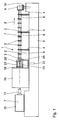
- eine Seiten-Längs-Ansicht einer als Zwei-Wellen-Extruder ausgebildeten Schnecken-Maschine,
- Fig. 2
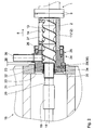
- einen vertikalen Teil-Längs-Schnitt durch die Schnecken-Maschine nach
Fig. 1 im Übergangs-Bereich von ihrem Gehäuse zum Getriebe, - Fig. 3
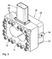
- eine perspektivische Ansicht eines Adapters aus dem Übergangs-Bereich nach
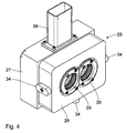
Fig. 2 , und - Fig. 4
- eine weitere perspektivische Ansicht des Adapters.
- Bei der in der Zeichnung dargestellten Schnecken-Maschine handelt es sich um einen üblichen Extruder. Dieser weist ein Gehäuse 1 auf, das aus einzelnen Gehäuse-Abschnitten 2, sogenannten Gehäuseschüssen, zusammengesetzt ist, die mittels Flanschen 3 miteinander verbunden sind. Das Gehäuse 1 ist mittels Stützen 4 gegenüber einem Fundament 5 abgestützt, wobei zwischen den Stützen 4 und dem Gehäuse 1 Schiebe-Lager 6 ausgebildet sind, mittels derer das Gehäuse 1 in Richtung seiner Längs-Achse 7 verschiebbar ist. Die Abstützung über die Stützen 4 erfolgt also im Wesentlichen in vertikaler Richtung. Im Bereich eines in einer Produktions-Richtung 8 stromabwärtigen Austrags-Ende 9 ist das Gehäuse 1 über eine Verbindung 10 sowohl in vertikaler Richtung als auch in Richtung der Längs-Achse 7 festgelegt. Dieses Austrags-Ende 9 des Gehäuses 1 ist also ortsfest fixiert.
- Die Schnecken-Maschine ist als Zwei-Wellen-Extruder ausgebildet; d. h. sie weist zwei in Richtung der zueinander parallelen Längs-Achsen 7 verlaufende, einander 8-förmig durchdringende Schnecken-Bohrungen 11, 12 auf, in denen parallel zueinander zwei Schneckenwellen 13, 14 angeordnet sind, die dichtkämmend ausgebildet sind.
- Der Antrieb der Schnecken-Wellen 13, 14 erfolgt über einen Elektro-Motor 15, und ein Untersetzungs- und Verzweigungs-Getriebe 16, wobei zwischen Motor 15 und Getriebe 16 eine Kupplung 17 angeordnet ist. Die Abtriebs-Wellen 18 des Getriebes 16 sind in üblicher Weise mittels Kupplungs-Hülsen 19 mit den Antriebs-Zapfen 20 der Schnecken-Wellen 13, 14 verbunden. Diese Kupplungs-Hülsen 19 befinden sich in einem Ansatz-Gehäuse 21, einer sogenannten Laterne, des Getriebes 16. Dieses Ansatz-Gehäuse 21 ist ebenfalls mittels einer Abstützung 22 gegenüber dem Fundament 5 in vertikaler Richtung abgestützt.
- Das Gehäuse 1, d. h. der dem Ansatz-Gehäuse 21 nächstliegende ein Zuführ-Ende bildende Gehäuse-Abschnitt 2, ist nicht - wie üblich - in Richtung der Längs-Achse 7 fest mit dem Ansatz-Gehäuse 21 verbunden, sondern in dessen zugewandter Stirn-Wand 23 mittels einer Schiebe-Verbindung 24 in Richtung der Längs-Achse 7 verschiebbar geführt und senkrecht hierzu, also in vertikaler und horizontal quer zur Längs-Achse 7 verlaufender Richtung, fest abgestützt.
- Hierzu ist am Flansch 3 des erwähnten dem Ansatz-Gehäuse 21 benachbarten Gehäuse-Abschnitt 2 ein Adapter 25 mittels Schrauben 26 befestigt. Der Adapter 25 weist zwei Abschnitte auf, nämlich einen dem benachbarten Gehäuse-Abschnitt 2 benachbarten Schnecken-Bohrungs-Abschnitt 27 und einen Lager-Abschnitt 28. Im Schnecken-Bohrungs-Abschnitt 27, der mittels der Schrauben 26 mit dem benachbarten Gehäuse-Abschnitt 2 verbunden wird, sind die jeweiligen Anfänge der Schnecken-Bohrungen 11, 12 ausgebildet, in die - wie
Fig. 2 entnehmbar ist - die Schnecken-Wellen 13, 14 hineinragen. Im Lager-Abschnitt 28 sind Lager-Bohrungen 29, 30 ausgebildet, in denen die Antriebs-Zapfen 20 der Schnecken-Wellen 13, 14 drehbar gelagert und mittels Dichtungen 32, beispielsweise Stopfbuchs-Packungen, abgedichtet sind. - Der Lager-Abschnitt 28 ist in einer angepassten Lager-Öffnung 33 in der Stirn-Wand 23 des Ansatz-Gehäuses 21 in Richtung der Achse verschiebbar gelagert, senkrecht hierzu aber abgestützt. Zusätzlich sind am Lager-Abschnitt 28 Pass-Federn 34 angebracht, die in entsprechenden FührungsNuten 35 in der Stirn-Wand 23 geführt sind.
- Aus den Schnecken-Bohrungen 11, 12 im Schnecken-Bohrungs-Abschnitt 27 des Adapters 25 mündet ein Rückwärtsentgasungs-Kanal 36 aus. In Produktions-Richtung 8 unmittelbar dahinter ist im ersten benachbarten Gehäuse-Abschnitt eine Zuführ-Öffnung 37 für das in der Schnecken-Maschine aufzubereitende oder zu bearbeitende Material ausgebildet.
- Der Wirkungsmechanismus ist folgender:
- Insbesondere durch das Aufheizen während der Inbetriebnahme dehnen sich die Schnecken-Wellen 13, 14 einerseits und das Gehäuse 1 andererseits aufgrund der starken Temperaturerhöhung von Raumtemperatur auf Temperaturen über 200°C und gegebenenfalls sogar über 300°C stark aus. Die in üblicher Weise gegenüber dem Getriebe 16 in Richtung der Längs-Achse 7 festgelegten Schnecken-Wellen 13, 14 dehnen sich in Richtung zum Ende 9 des Gehäuses 1, d. h. in Richtung zu ihren nicht dargestellten Schnecken-Spitzen, aus, wie dies allgemein üblich ist. Das Gehäuse 1 ist im Bereich seines Austrags-Endes 9 so ausgebildet, dass die Schnecken-Wellen 13, 14 sich im Gehäuse 1 zu dessen Ende hin ausdehnen können.
- Das Gehäuse 1 dagegen dehnt sich aufgrund der geschilderten Ausgestaltung in Richtung zum Getriebe 16 hin aus, wobei das maximale Axial-Spiel 38 zwischen dem Schnecken-Bohrungs-Abschnitt 27 und der Stirn-Wand 23 so groß bemessen ist, dass der Lager-Abschnitt 28 sich in ausreichendem Maß in der Lager-Öffnung 33 zum Getriebe 16 hin verschieben kann.
Claims (9)
- Schnecken-Maschine,- mit einem Gehäuse (1), das-- ein Zuführ-Ende,-- ein Austrags-Ende (9) und-- eine Zuführ-Öffnung (37) am Zuführ-Ende aufweist,- mit mindestens einer im Gehäuse (1) ausgebildeten Schnecken-Bohrung (11, 12) mit einer Längs-Achse (7),- mit einer in der Schnecken-Bohrung (11, 12) drehbar angeordneten Schnecken-Welle (13, 14),- mit einem Antriebs-Motor (15),- mit einem mit dem Antriebs-Motor (15) in Antriebsverbindung stehenden Getriebe (16),dadurch gekennzeichnet,-- das eine mit der Schnecken-Welle (13, 14) verbundene Abtriebs-Welle (18) aufweist,
dass zwischen dem Gehäuse (1) und dem Getriebe (16) eine Schiebe-Verbindung (24) in Richtung der Längs-Achse (7) ausgebildet ist. - Schnecken-Maschine nach Anspruch 1, dadurch gekennzeichnet, dass die Schiebe-Verbindung (24) einen Adapter (25) aufweist, der einen mit dem Gehäuse (1) verbundenen Schnecken-Bohrungs-Abschnitt (27) und einen dem Getriebe (16) zugewandten Lager-Abschnitt (28) aufweist.
- Schnecken-Maschine nach Anspruch 1 oder 2, dadurch gekennzeichnet,
dass am Getriebe (16) ein die Abtriebs-Welle (18) umgebendes Ansatz-Gehäuse (21) vorgesehen ist, das eine das Gehäuse (1) quer zur Längs-Achse (7) abstützende Lager-Öffnung (33) aufweist. - Schnecken-Maschine nach Anspruch 2 und 3, dadurch gekennzeichnet,
dass der Lager-Abschnitt (28) des Adapters (25) in der Lager-Öffnung (33) in Richtung der Längs-Achse (7) verschiebbar abgestützt ist. - Schnecken-Maschine nach einem der Ansprüche 1 bis 4, dadurch gekennzeichnet,
dass die Schnecken-Welle (13, 14) in Richtung der Längs-Achse (7) unverschiebbar mit der Abtriebs-Welle (18) verbunden ist. - Schnecken-Maschine nach einem der Ansprüche 2 bis 5, dadurch gekennzeichnet,
dass die Schnecken-Welle (13, 14) bis in den Schnecken-Bohrungs-Abschnitt (27) des Adapters (25) hineinragt. - Schnecken-Maschine nach einem der Ansprüche 2 bis 6, dadurch gekennzeichnet,
dass ein Antriebs-Zapfen (20) der Schnecken-Welle (13, 14) in einer Lager-Bohrung (29, 30) des Adapters (25) gelagert ist. - Schnecken-Maschine nach einem der Ansprüche 1 bis 8, dadurch gekennzeichnet,
dass das Austrags-Ende (9) des Gehäuses (1) in Richtung der Längs-Achse (7) festlegbar ist. - Schnecken-Maschine nach einem der Ansprüche 1 bis 8, dadurch gekennzeichnet,
dass sie als Zwei-Wellen-Extruder ausgebildet ist.
Priority Applications (5)
| Application Number | Priority Date | Filing Date | Title |
|---|---|---|---|
| EP08021246A EP2193907B1 (de) | 2008-12-06 | 2008-12-06 | Schnecken-Maschine mit axialem Ausgleich für thermische Ausdehnung |
| AT08021246T ATE509754T1 (de) | 2008-12-06 | 2008-12-06 | Schnecken-maschine mit axialem ausgleich für thermische ausdehnung |
| JP2009268598A JP5380256B2 (ja) | 2008-12-06 | 2009-11-26 | スクリュー機械 |
| US12/630,413 US8500433B2 (en) | 2008-12-06 | 2009-12-03 | Screw machine |
| CN2009102533508A CN101746037B (zh) | 2008-12-06 | 2009-12-07 | 螺旋式机器 |
Applications Claiming Priority (1)
| Application Number | Priority Date | Filing Date | Title |
|---|---|---|---|
| EP08021246A EP2193907B1 (de) | 2008-12-06 | 2008-12-06 | Schnecken-Maschine mit axialem Ausgleich für thermische Ausdehnung |
Publications (2)
| Publication Number | Publication Date |
|---|---|
| EP2193907A1 true EP2193907A1 (de) | 2010-06-09 |
| EP2193907B1 EP2193907B1 (de) | 2011-05-18 |
Family
ID=40568411
Family Applications (1)
| Application Number | Title | Priority Date | Filing Date |
|---|---|---|---|
| EP08021246A Active EP2193907B1 (de) | 2008-12-06 | 2008-12-06 | Schnecken-Maschine mit axialem Ausgleich für thermische Ausdehnung |
Country Status (5)
| Country | Link |
|---|---|
| US (1) | US8500433B2 (de) |
| EP (1) | EP2193907B1 (de) |
| JP (1) | JP5380256B2 (de) |
| CN (1) | CN101746037B (de) |
| AT (1) | ATE509754T1 (de) |
Cited By (3)
| Publication number | Priority date | Publication date | Assignee | Title |
|---|---|---|---|---|
| EP2946904A1 (de) | 2014-05-22 | 2015-11-25 | Coperion GmbH | Vorrichtung und Verfahren zur Entgasung von aufzubereitendem Material |
| CN105313295A (zh) * | 2015-10-20 | 2016-02-10 | 常州市鑫尔减速机有限公司 | 吊装型流延挤出机 |
| DE102015120586A1 (de) * | 2015-09-08 | 2017-03-09 | Blach Verwaltungs Gmbh & Co. Kg | RingExtruder zur kontinuierlichen Aufbereitung von Gummimassen mit Co-Extruder und Kühlsystem |
Families Citing this family (2)
| Publication number | Priority date | Publication date | Assignee | Title |
|---|---|---|---|---|
| JP2014133389A (ja) * | 2013-01-11 | 2014-07-24 | Sekisui Chem Co Ltd | 2軸異方向回転押出機 |
| EP3656523B1 (de) | 2018-11-22 | 2021-09-29 | Buss AG | Misch- und knetmaschine mit wirksamer entlüftung im bereich der zuführung, und darauf bezogenes verfahren |
Citations (6)
| Publication number | Priority date | Publication date | Assignee | Title |
|---|---|---|---|---|
| US4004787A (en) * | 1975-01-10 | 1977-01-25 | Usm Corporation | Mixing and venting extruder |
| EP0734825A1 (de) * | 1995-03-27 | 1996-10-02 | Basf Aktiengesellschaft | Verfahren zur Herstellung von Thermoplasten |
| EP0849065A1 (de) | 1996-12-19 | 1998-06-24 | Hoechst Trespaphan GmbH | Kompensator zum Ausgleich der durch Temperatureinflüssen hervorgerufenen Längenänderungen |
| US20060076705A1 (en) | 2004-10-11 | 2006-04-13 | Fowler J N | Multiple extruder assembly and process for continuous reactive extrusion |
| DE102004051203A1 (de) * | 2004-10-20 | 2006-05-04 | Extricom Gmbh | Extruder |
| EP1990176A1 (de) | 2007-05-11 | 2008-11-12 | DMT Technology GmbH | Verlängerbare Schmelzzuführungsleitung |
Family Cites Families (9)
| Publication number | Priority date | Publication date | Assignee | Title |
|---|---|---|---|---|
| US3638921A (en) * | 1969-02-25 | 1972-02-01 | French Oil Mill Machinery | Apparatus for treating elastomeric materials |
| JPS5230751A (en) * | 1975-09-05 | 1977-03-08 | Japan Steel Works Ltd | Method and device to eliminate cylinder displacement owing to thermal expansion for vertical type extruder |
| JPS5837459Y2 (ja) * | 1978-05-22 | 1983-08-24 | 株式会社日本製鋼所 | 連続混練機等におけるシリンダ前後移動用圧力シリンダの固定装置 |
| US4385553A (en) * | 1980-01-21 | 1983-05-31 | Tokyo Electric Co., Ltd. | Apparatus for separating liquid and residual solids |
| JPS574398A (en) * | 1980-06-07 | 1982-01-09 | Seiichi Yamazaki | Screw type extrusion dehydrating machine |
| JPS58156527U (ja) * | 1982-04-12 | 1983-10-19 | 株式会社神戸製鋼所 | 混練機の軸封装置 |
| JP2971710B2 (ja) * | 1993-09-29 | 1999-11-08 | 株式会社日本製鋼所 | 押出機 |
| US20060076706A1 (en) * | 2004-01-16 | 2006-04-13 | Buethorn Donald R | Foot orthosis support device method and apparatus |
| CN2745732Y (zh) * | 2004-11-05 | 2005-12-14 | 汕头市奇佳机械厂有限公司 | 一种多层共挤型材挤出机机组 |
-
2008
- 2008-12-06 EP EP08021246A patent/EP2193907B1/de active Active
- 2008-12-06 AT AT08021246T patent/ATE509754T1/de active
-
2009
- 2009-11-26 JP JP2009268598A patent/JP5380256B2/ja active Active
- 2009-12-03 US US12/630,413 patent/US8500433B2/en active Active
- 2009-12-07 CN CN2009102533508A patent/CN101746037B/zh not_active Expired - Fee Related
Patent Citations (7)
| Publication number | Priority date | Publication date | Assignee | Title |
|---|---|---|---|---|
| US4004787A (en) * | 1975-01-10 | 1977-01-25 | Usm Corporation | Mixing and venting extruder |
| EP0734825A1 (de) * | 1995-03-27 | 1996-10-02 | Basf Aktiengesellschaft | Verfahren zur Herstellung von Thermoplasten |
| EP0849065A1 (de) | 1996-12-19 | 1998-06-24 | Hoechst Trespaphan GmbH | Kompensator zum Ausgleich der durch Temperatureinflüssen hervorgerufenen Längenänderungen |
| US5865472A (en) | 1996-12-19 | 1999-02-02 | Hoechst Trespaphan Gmbh | Compensator for temperature-caused length changes |
| US20060076705A1 (en) | 2004-10-11 | 2006-04-13 | Fowler J N | Multiple extruder assembly and process for continuous reactive extrusion |
| DE102004051203A1 (de) * | 2004-10-20 | 2006-05-04 | Extricom Gmbh | Extruder |
| EP1990176A1 (de) | 2007-05-11 | 2008-11-12 | DMT Technology GmbH | Verlängerbare Schmelzzuführungsleitung |
Cited By (4)
| Publication number | Priority date | Publication date | Assignee | Title |
|---|---|---|---|---|
| EP2946904A1 (de) | 2014-05-22 | 2015-11-25 | Coperion GmbH | Vorrichtung und Verfahren zur Entgasung von aufzubereitendem Material |
| DE102015120586A1 (de) * | 2015-09-08 | 2017-03-09 | Blach Verwaltungs Gmbh & Co. Kg | RingExtruder zur kontinuierlichen Aufbereitung von Gummimassen mit Co-Extruder und Kühlsystem |
| DE102015120586B4 (de) * | 2015-09-08 | 2018-10-18 | Blach Verwaltungs Gmbh & Co. Kg | Ringextruder zur kontinuierlichen Aufbereitung von Gummimaterial mit Co-Extruder, Anlage und Verfahren zur Vorverarbeitung eines kontinuierlich aufzubereitenden Gummimaterials |
| CN105313295A (zh) * | 2015-10-20 | 2016-02-10 | 常州市鑫尔减速机有限公司 | 吊装型流延挤出机 |
Also Published As
| Publication number | Publication date |
|---|---|
| CN101746037A (zh) | 2010-06-23 |
| CN101746037B (zh) | 2012-12-12 |
| US20100143518A1 (en) | 2010-06-10 |
| EP2193907B1 (de) | 2011-05-18 |
| JP2010131673A (ja) | 2010-06-17 |
| US8500433B2 (en) | 2013-08-06 |
| ATE509754T1 (de) | 2011-06-15 |
| JP5380256B2 (ja) | 2014-01-08 |
Similar Documents
| Publication | Publication Date | Title |
|---|---|---|
| DE10015340C2 (de) | Walzgerüst für Walzstraßen zum Walzen von metallischen Rohren, Stäben oder Drähten | |
| DE3118498C2 (de) | Ölgekühlte Zylinderlaufbüchse | |
| EP1995417A1 (de) | Nockenwelle | |
| DE102012103147A1 (de) | Loslager für ein lenkgetriebe | |
| EP2193907B1 (de) | Schnecken-Maschine mit axialem Ausgleich für thermische Ausdehnung | |
| EP0324168A2 (de) | Walzwerksantrieb mit Zahngelenkspindel | |
| EP3284966A1 (de) | Lageranordnung, insbesondere für eine strömungsmaschine, und strömungsmaschine mit einer derartigen lageranordnung | |
| EP2002136A1 (de) | Hydrodynamisches axialgleitlager und zugehöriges betriebsverfahren | |
| EP0865837B1 (de) | Walzwerksantrieb mit Zahngelenkspindeln und mit einer Vorrichtung zur Umlaufschmierung | |
| EP2082862B1 (de) | Extruder | |
| WO2007121821A1 (de) | Strangführungsrolle | |
| DE102016209654B4 (de) | Temperierbare Spindelbaugruppe mit Fluideinführschlauch | |
| EP1925423B1 (de) | Anlage zum Aufbereiten von Stoffen | |
| DE10066008B4 (de) | Schrägachsenverstelleinheit mit Kühlung durch einen Ölmassenstrom | |
| EP2842716B1 (de) | Schneckenmaschine und Verfahren zur Aufbereitung von Kunststoffschmelzen | |
| DE1729149B2 (de) | Vorrichtung mit einer oder mehreren Schnecken, insbesondere Strangpresse | |
| DE3417699C2 (de) | ||
| EP1008437A1 (de) | Getriebe für einen Doppelschneckenextruder | |
| DE102019134040A1 (de) | Reinigungsvorrichtung | |
| DE102021214449B3 (de) | Doppelschneckenförderer | |
| EP1319866A1 (de) | Getriebemotor | |
| DE102007042248B4 (de) | Werkzeugkopf | |
| DE2911000C2 (de) | Drehdurchführung für die Einleitung strömungsfähiger Medien in ein rotierendes Maschinenteil | |
| DE102017206686A1 (de) | Lageranordnung zur Lagerung einer Getriebewelle | |
| DE202016103920U1 (de) | Strangführungsrolle zum Führen eines metallischen Strangs in einer Stranggießanlage |
Legal Events
| Date | Code | Title | Description |
|---|---|---|---|
| PUAI | Public reference made under article 153(3) epc to a published international application that has entered the european phase |
Free format text: ORIGINAL CODE: 0009012 |
|
| AK | Designated contracting states |
Kind code of ref document: A1 Designated state(s): AT BE BG CH CY CZ DE DK EE ES FI FR GB GR HR HU IE IS IT LI LT LU LV MC MT NL NO PL PT RO SE SI SK TR |
|
| AX | Request for extension of the european patent |
Extension state: AL BA MK RS |
|
| 17P | Request for examination filed |
Effective date: 20100713 |
|
| 17Q | First examination report despatched |
Effective date: 20100812 |
|
| GRAP | Despatch of communication of intention to grant a patent |
Free format text: ORIGINAL CODE: EPIDOSNIGR1 |
|
| AKX | Designation fees paid |
Designated state(s): AT BE BG CH CY CZ DE DK EE ES FI FR GB GR HR HU IE IS IT LI LT LU LV MC MT NL NO PL PT RO SE SI SK TR |
|
| GRAS | Grant fee paid |
Free format text: ORIGINAL CODE: EPIDOSNIGR3 |
|
| GRAA | (expected) grant |
Free format text: ORIGINAL CODE: 0009210 |
|
| REG | Reference to a national code |
Ref country code: GB Ref legal event code: FG4D Free format text: NOT ENGLISH |
|
| REG | Reference to a national code |
Ref country code: CH Ref legal event code: EP |
|
| REG | Reference to a national code |
Ref country code: IE Ref legal event code: FG4D Free format text: LANGUAGE OF EP DOCUMENT: GERMAN |
|
| REG | Reference to a national code |
Ref country code: DE Ref legal event code: R096 Ref document number: 502008003616 Country of ref document: DE Effective date: 20110630 |
|
| REG | Reference to a national code |
Ref country code: NL Ref legal event code: VDEP Effective date: 20110518 |
|
| PG25 | Lapsed in a contracting state [announced via postgrant information from national office to epo] |
Ref country code: SE Free format text: LAPSE BECAUSE OF FAILURE TO SUBMIT A TRANSLATION OF THE DESCRIPTION OR TO PAY THE FEE WITHIN THE PRESCRIBED TIME-LIMIT Effective date: 20110518 Ref country code: NO Free format text: LAPSE BECAUSE OF FAILURE TO SUBMIT A TRANSLATION OF THE DESCRIPTION OR TO PAY THE FEE WITHIN THE PRESCRIBED TIME-LIMIT Effective date: 20110818 Ref country code: HR Free format text: LAPSE BECAUSE OF FAILURE TO SUBMIT A TRANSLATION OF THE DESCRIPTION OR TO PAY THE FEE WITHIN THE PRESCRIBED TIME-LIMIT Effective date: 20110518 Ref country code: LT Free format text: LAPSE BECAUSE OF FAILURE TO SUBMIT A TRANSLATION OF THE DESCRIPTION OR TO PAY THE FEE WITHIN THE PRESCRIBED TIME-LIMIT Effective date: 20110518 Ref country code: PT Free format text: LAPSE BECAUSE OF FAILURE TO SUBMIT A TRANSLATION OF THE DESCRIPTION OR TO PAY THE FEE WITHIN THE PRESCRIBED TIME-LIMIT Effective date: 20110919 |
|
| PG25 | Lapsed in a contracting state [announced via postgrant information from national office to epo] |
Ref country code: CY Free format text: LAPSE BECAUSE OF FAILURE TO SUBMIT A TRANSLATION OF THE DESCRIPTION OR TO PAY THE FEE WITHIN THE PRESCRIBED TIME-LIMIT Effective date: 20110518 Ref country code: IS Free format text: LAPSE BECAUSE OF FAILURE TO SUBMIT A TRANSLATION OF THE DESCRIPTION OR TO PAY THE FEE WITHIN THE PRESCRIBED TIME-LIMIT Effective date: 20110918 Ref country code: SI Free format text: LAPSE BECAUSE OF FAILURE TO SUBMIT A TRANSLATION OF THE DESCRIPTION OR TO PAY THE FEE WITHIN THE PRESCRIBED TIME-LIMIT Effective date: 20110518 Ref country code: GR Free format text: LAPSE BECAUSE OF FAILURE TO SUBMIT A TRANSLATION OF THE DESCRIPTION OR TO PAY THE FEE WITHIN THE PRESCRIBED TIME-LIMIT Effective date: 20110819 Ref country code: FI Free format text: LAPSE BECAUSE OF FAILURE TO SUBMIT A TRANSLATION OF THE DESCRIPTION OR TO PAY THE FEE WITHIN THE PRESCRIBED TIME-LIMIT Effective date: 20110518 Ref country code: ES Free format text: LAPSE BECAUSE OF FAILURE TO SUBMIT A TRANSLATION OF THE DESCRIPTION OR TO PAY THE FEE WITHIN THE PRESCRIBED TIME-LIMIT Effective date: 20110829 Ref country code: LV Free format text: LAPSE BECAUSE OF FAILURE TO SUBMIT A TRANSLATION OF THE DESCRIPTION OR TO PAY THE FEE WITHIN THE PRESCRIBED TIME-LIMIT Effective date: 20110518 |
|
| REG | Reference to a national code |
Ref country code: IE Ref legal event code: FD4D |
|
| PG25 | Lapsed in a contracting state [announced via postgrant information from national office to epo] |
Ref country code: NL Free format text: LAPSE BECAUSE OF FAILURE TO SUBMIT A TRANSLATION OF THE DESCRIPTION OR TO PAY THE FEE WITHIN THE PRESCRIBED TIME-LIMIT Effective date: 20110518 |
|
| PG25 | Lapsed in a contracting state [announced via postgrant information from national office to epo] |
Ref country code: CZ Free format text: LAPSE BECAUSE OF FAILURE TO SUBMIT A TRANSLATION OF THE DESCRIPTION OR TO PAY THE FEE WITHIN THE PRESCRIBED TIME-LIMIT Effective date: 20110518 Ref country code: IE Free format text: LAPSE BECAUSE OF FAILURE TO SUBMIT A TRANSLATION OF THE DESCRIPTION OR TO PAY THE FEE WITHIN THE PRESCRIBED TIME-LIMIT Effective date: 20110518 Ref country code: EE Free format text: LAPSE BECAUSE OF FAILURE TO SUBMIT A TRANSLATION OF THE DESCRIPTION OR TO PAY THE FEE WITHIN THE PRESCRIBED TIME-LIMIT Effective date: 20110518 |
|
| PG25 | Lapsed in a contracting state [announced via postgrant information from national office to epo] |
Ref country code: SK Free format text: LAPSE BECAUSE OF FAILURE TO SUBMIT A TRANSLATION OF THE DESCRIPTION OR TO PAY THE FEE WITHIN THE PRESCRIBED TIME-LIMIT Effective date: 20110518 Ref country code: RO Free format text: LAPSE BECAUSE OF FAILURE TO SUBMIT A TRANSLATION OF THE DESCRIPTION OR TO PAY THE FEE WITHIN THE PRESCRIBED TIME-LIMIT Effective date: 20110518 Ref country code: PL Free format text: LAPSE BECAUSE OF FAILURE TO SUBMIT A TRANSLATION OF THE DESCRIPTION OR TO PAY THE FEE WITHIN THE PRESCRIBED TIME-LIMIT Effective date: 20110518 Ref country code: DK Free format text: LAPSE BECAUSE OF FAILURE TO SUBMIT A TRANSLATION OF THE DESCRIPTION OR TO PAY THE FEE WITHIN THE PRESCRIBED TIME-LIMIT Effective date: 20110518 |
|
| PLBE | No opposition filed within time limit |
Free format text: ORIGINAL CODE: 0009261 |
|
| STAA | Information on the status of an ep patent application or granted ep patent |
Free format text: STATUS: NO OPPOSITION FILED WITHIN TIME LIMIT |
|
| 26N | No opposition filed |
Effective date: 20120221 |
|
| REG | Reference to a national code |
Ref country code: DE Ref legal event code: R097 Ref document number: 502008003616 Country of ref document: DE Effective date: 20120221 |
|
| BERE | Be: lapsed |
Owner name: COPERION G.M.B.H. Effective date: 20111231 |
|
| PG25 | Lapsed in a contracting state [announced via postgrant information from national office to epo] |
Ref country code: MC Free format text: LAPSE BECAUSE OF NON-PAYMENT OF DUE FEES Effective date: 20111231 |
|
| REG | Reference to a national code |
Ref country code: FR Ref legal event code: ST Effective date: 20120831 |
|
| PG25 | Lapsed in a contracting state [announced via postgrant information from national office to epo] |
Ref country code: BE Free format text: LAPSE BECAUSE OF NON-PAYMENT OF DUE FEES Effective date: 20111231 |
|
| PG25 | Lapsed in a contracting state [announced via postgrant information from national office to epo] |
Ref country code: MT Free format text: LAPSE BECAUSE OF FAILURE TO SUBMIT A TRANSLATION OF THE DESCRIPTION OR TO PAY THE FEE WITHIN THE PRESCRIBED TIME-LIMIT Effective date: 20110518 |
|
| PG25 | Lapsed in a contracting state [announced via postgrant information from national office to epo] |
Ref country code: FR Free format text: LAPSE BECAUSE OF NON-PAYMENT OF DUE FEES Effective date: 20120102 |
|
| PG25 | Lapsed in a contracting state [announced via postgrant information from national office to epo] |
Ref country code: LU Free format text: LAPSE BECAUSE OF NON-PAYMENT OF DUE FEES Effective date: 20111206 |
|
| PG25 | Lapsed in a contracting state [announced via postgrant information from national office to epo] |
Ref country code: BG Free format text: LAPSE BECAUSE OF FAILURE TO SUBMIT A TRANSLATION OF THE DESCRIPTION OR TO PAY THE FEE WITHIN THE PRESCRIBED TIME-LIMIT Effective date: 20110818 |
|
| REG | Reference to a national code |
Ref country code: CH Ref legal event code: PL |
|
| GBPC | Gb: european patent ceased through non-payment of renewal fee |
Effective date: 20121206 |
|
| PG25 | Lapsed in a contracting state [announced via postgrant information from national office to epo] |
Ref country code: TR Free format text: LAPSE BECAUSE OF FAILURE TO SUBMIT A TRANSLATION OF THE DESCRIPTION OR TO PAY THE FEE WITHIN THE PRESCRIBED TIME-LIMIT Effective date: 20110518 |
|
| PG25 | Lapsed in a contracting state [announced via postgrant information from national office to epo] |
Ref country code: CH Free format text: LAPSE BECAUSE OF NON-PAYMENT OF DUE FEES Effective date: 20121231 Ref country code: HU Free format text: LAPSE BECAUSE OF FAILURE TO SUBMIT A TRANSLATION OF THE DESCRIPTION OR TO PAY THE FEE WITHIN THE PRESCRIBED TIME-LIMIT Effective date: 20110518 Ref country code: LI Free format text: LAPSE BECAUSE OF NON-PAYMENT OF DUE FEES Effective date: 20121231 |
|
| PG25 | Lapsed in a contracting state [announced via postgrant information from national office to epo] |
Ref country code: GB Free format text: LAPSE BECAUSE OF NON-PAYMENT OF DUE FEES Effective date: 20121206 |
|
| REG | Reference to a national code |
Ref country code: AT Ref legal event code: MM01 Ref document number: 509754 Country of ref document: AT Kind code of ref document: T Effective date: 20131206 |
|
| PG25 | Lapsed in a contracting state [announced via postgrant information from national office to epo] |
Ref country code: AT Free format text: LAPSE BECAUSE OF NON-PAYMENT OF DUE FEES Effective date: 20131206 |
|
| PGFP | Annual fee paid to national office [announced via postgrant information from national office to epo] |
Ref country code: IT Payment date: 20171218 Year of fee payment: 10 |
|
| REG | Reference to a national code |
Ref country code: DE Ref legal event code: R079 Ref document number: 502008003616 Country of ref document: DE Free format text: PREVIOUS MAIN CLASS: B29C0047080000 Ipc: B29C0048250000 |
|
| PG25 | Lapsed in a contracting state [announced via postgrant information from national office to epo] |
Ref country code: IT Free format text: LAPSE BECAUSE OF NON-PAYMENT OF DUE FEES Effective date: 20181206 |
|
| PGFP | Annual fee paid to national office [announced via postgrant information from national office to epo] |
Ref country code: DE Payment date: 20241216 Year of fee payment: 17 |