EP2193946B1 - Dichtungsprofil - Google Patents
Dichtungsprofil Download PDFInfo
- Publication number
- EP2193946B1 EP2193946B1 EP09169876A EP09169876A EP2193946B1 EP 2193946 B1 EP2193946 B1 EP 2193946B1 EP 09169876 A EP09169876 A EP 09169876A EP 09169876 A EP09169876 A EP 09169876A EP 2193946 B1 EP2193946 B1 EP 2193946B1
- Authority
- EP
- European Patent Office
- Prior art keywords
- sealing
- sealing profile
- lip
- section
- profile according
- Prior art date
- Legal status (The legal status is an assumption and is not a legal conclusion. Google has not performed a legal analysis and makes no representation as to the accuracy of the status listed.)
- Not-in-force
Links
Images

Classifications
-
- B—PERFORMING OPERATIONS; TRANSPORTING
- B60—VEHICLES IN GENERAL
- B60J—WINDOWS, WINDSCREENS, NON-FIXED ROOFS, DOORS, OR SIMILAR DEVICES FOR VEHICLES; REMOVABLE EXTERNAL PROTECTIVE COVERINGS SPECIALLY ADAPTED FOR VEHICLES
- B60J10/00—Sealing arrangements
- B60J10/70—Sealing arrangements specially adapted for windows or windscreens
- B60J10/74—Sealing arrangements specially adapted for windows or windscreens for sliding window panes, e.g. sash guides
- B60J10/76—Sealing arrangements specially adapted for windows or windscreens for sliding window panes, e.g. sash guides for window sashes; for glass run channels
Definitions
- the invention relates to a sealing profile with a substantially U-shaped cross-section for receiving and sealing a displaceable closing element, in particular for a motor vehicle.
- the sealing profile has a base portion and at least one leg portion. At least one sealing lip protrudes from the base section and / or the leg section for sealing the closing element.
- sealing profiles are from the WO 2004/050408 A1 known and are often used to seal sliding lock elements at its edge area and store.
- the sealing profiles In order to ensure a basic rigidity of the sealing profile and at the same time to achieve a reliable sealing of the closing element, the sealing profiles have a fixed basic structure consisting of a base section and at least one leg section. At this basic structure flexible sealing lips are attached, which can be applied to the closing element and this seal securely due to their flexibility.
- sealing profile of the type mentioned Another important function of a sealing profile of the type mentioned is the storage of the closing element. If the sealing profile is exposed to vibrations, for example in a motor vehicle, this is a concern to wear, that the closing element is firmly and safely stored and, among other things, a noise nuisance is avoided.
- sealing profiles of the type mentioned have a plurality of sealing lips.
- the closing elements are often moved during their assembly relative to the sealing profile and thus also to the sealing lips, while the sealing lips, possibly with great pressure, abut against the closing element. This makes it possible that in comparison to the rest of the sealing profile very elastic and soft sealing lips deform, in particular, that form wrinkles or that the sealing lip is pushed aside and engaged behind and thus the closing element is applied directly to the basic structure of the sealing profile.
- the invention is based on the object , a sealing profile of the type mentioned in such a way that in a simple manner secure sealing and storage of the closing element is ensured.
- the sealing profile according to the invention is characterized in that the sealing lip in the region of a distal end, which can be applied to the closing element, by means of a mechanical holding means which is adapted to be inserted from the outside into the sealing profile, in a predetermined position on the base portion and / or is at least locally fixed to the leg portion.
- Mechanical holding means can be easily and inexpensively inserted from the outside into the sealing profile, whereas the application of a chemical holding means, such as an adhesive, made it necessary to apply the adhesive exactly in hard to reach places of the sealing profile.
- the substantially U-shaped cross-section of the sealing profile serves to enclose the closing element at its edge and to be able to store and seal it more securely.
- the mechanical holding means may comprise a thread, by means of which the sealing lip is sewn to the base portion and / or the leg portion.
- Such seams are inexpensive to produce. Furthermore, they are easy to position and offer great strength.
- the mechanical holding means may alternatively or additionally comprise a clip. Also, this attachment has the advantage that it does not require access to hidden and difficult to access parts of the sealing profile.
- the mechanical holding means may be designed to be detachable, in order to loosen the fixed sealing lip again after the closing element has been installed and thus to allow it to better adapt to the surface of the closing element and thereby to provide improved sealing of the closing element.
- the proximal end of the sealing lip can advantageously be integrally connected to the base section and / or the leg section. In this case, the production of such a sealing profile is easier, since the sealing lip can be produced together with the base portion and / or the leg portion. Later mounting steps for the sealing lip omitted.
- the sealing lip may be a bottom lip provided near the base portion for sealing a front of the closing element. This achieves, in particular, good damping of vibrations oscillating perpendicular to the surface of the front.
- the sealing lip expediently has a friction-reducing coating, in particular a flocking. This considerably reduces the running noise when the displaceable closing element moves.
- the base portion and / or the leg portions and / or the sealing lips may be extruded. Such an extruded profile only has to be cut to length to comply with the dimensions. A production in the exact required length is not required. At least the base portion may include a drawstring. Such a drawstring simplifies the production of the sealing profile by means of extrusion.
- the base portion and / or the leg portions and / or the sealing lips may be made of an elastomeric material, in particular ethylene-propylene-diene rubber (EPDM) or a thermoplastic elastomer (TPE). Elastomers are particularly suitable for the production of sealing profiles.
- EPDM ethylene-propylene-diene rubber
- TPE thermoplastic elastomer
- door 10 of a motor vehicle has in the region of an opening 12 a sliding closure member 14, which is formed here by a window pane.
- the window pane 14 is supported and guided by a sealing profile 16, which extends in an edge region of the window pane 14 along the edge and covers it.
- a front 15 of the window pane 14 is enclosed by the sealing profile 16.
- the sealing profile 16 which in the dismantled state in Fig. 2 is shown, has a base portion 20 and two leg portions 22, 24. Of the leg portion 24 project sealing lips 26, 28, 30 in the direction of the leg portion 22 to and into a gap 25 in from. Since the sealing lip 26 is in the vicinity of the base portion 20, which forms a bottom in the installed state of the sealing profile 16, the sealing lip 26 is called bottom lip.
- the bottom lip 26, the sealing lips 28, 30 and the leg portion 22 are provided with a flocking 32 for reducing the frictional resistance.
- This flocking 32 is applied on the side remote from the bottom portion 20 side of the bottom lip 26 and the sealing lips 28, 30, so that the window 14 comes when inserting first with good sliding surfaces in touch.
- the bottom lip 26 and the sealing lips 28, 30 each have a proximal end 34 to the leg portion 34 where they are connected to the leg portion 24.
- a distal end 36 of the bottom lip 26 and the sealing lips 28, 30 projects as a free end into the gap 25 between the leg portion 22 and the leg portion 24 a.
- proximal and distal refer to a frame formed by the base portion 20 and the leg portions 22,24.
- the proximal end 34 is thus the end attached to the leg portion 22, 24 or Base portion 20 attached, so close to this is.
- the distal end 36 is away from this attachment location.
- the sealing lips 28, 30 protrude at an angle from the leg portion 24, so that they are inclined relative to a perpendicular to the leg portion 24 mounting.
- the sealing lips 28, 30 are inclined in the direction of the bottom portion 20.
- the sealing lips 28, 30 are deformed to the bottom portion 20, whereby they are pivoted about the proximal end 34 and extend at its distal end 36 substantially parallel to the leg portion 24.
- recesses 31 are provided at the proximal ends 34.
- projections 38 are provided which can be fixed by hooking to a mounting rail or a mounting flange. Furthermore, a retaining lip 40 is provided on the leg portion 24, which serves to secure the sealing profile 16 to a mounting flange (not shown).
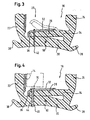
- Fig. 3 In order to prevent that in the embodiment of Fig. 2 free-floating bottom lip 26 is deformed during installation of the window pane 14 and possibly engaged behind, is in the first embodiment of the invention, the in Fig. 3 is shown, the bottom lip 26 by means of a thread 42 in a position close to the base portion 20 fixed. This effectively prevents the bottom lip 26 from shifting and thereby folding.
- the dashed line shows the shape of the bottom lip 26, if it hangs freely without fixation by the thread 42.
- the thread 42 is prior to installation of the sealing profile 16 by a sewing device along a longitudinal direction of the sealing profile 16 in the sealing profile sewn.
- the suturing device inserts the thread 42 in short sections of 8 to 15 stitches into the sealing profile 16, between which several centimeters are spaced. These seam portions are usually sufficient to fix the bottom lip 26.
- the thread 42 may be sewn so that it can be removed after installation of the window pane 14. For example, it would be possible to provide an access through which the thread 42 can be pulled out.
- the bottom lip 26 is attached to the base portion 20 by means of a clip 44 having barbs 46.
- a through-hole is drilled through the base portion 20 and the bottom lip 26, through which the clip is subsequently guided.
- the barbs 46 the clip remains reliably anchored in the base portion 20.
- a screw or the like can be used.
- the bottom lip 26 fix only in places. As a result, the positioning of the bottom lip 26 is ensured, while the unfixed areas of the bottom lip 26 can create a sealing effect and sound-reducing with greater force flat against the window pane 14.
- the provision of a mechanical holding device that is to say a thread 42 or a clip 44, is also possible for fixing the sealing lips 28, 30 to the leg section 24.
- the bottom lip 26 or the sealing lip 28, 30 need not be fixed to a base or leg portion 20, 22, 24, with which they are connected at its proximal end 34.
- the bottom lip 26 and the sealing lips 28, 30 are coextruded with the base portion 20 and the leg portions 22, 24.
- the sealing profile 16 is extruded from elastomers suitable for seals, for example EPDM. To support the extrusion process and to increase the strength of the base portion 20, this has a drawstring 50 on.
- the sealing profile 16 according to the invention allows reliable sealing and mounting of the window pane 14 and is easy to implement.
Landscapes
- Engineering & Computer Science (AREA)
- Mechanical Engineering (AREA)
- Seal Device For Vehicle (AREA)
- Gasket Seals (AREA)
- Specific Sealing Or Ventilating Devices For Doors And Windows (AREA)
Description
- Die Erfindung betrifft ein Dichtungsprofil mit einem im Wesentlichen U-förmigen Querschnitt zur Aufnahme und Abdichtung eines verschiebbaren Schließelements, insbesondere für ein Kraftfahrzeug. Das Dichtungsprofil weist einen Basisabschnitt und wenigstens einen Schenkelabschnitt auf. Von dem Basisabschnitt und/odet dem Schenkelabschnitt ragt wenigstens eine Dichtlippe zur Abdichtung des Schließelements ab.
- Derartige Dichtungsprofile sind aus der
WO 2004/050408 A1 bekannt und werden häufig eingesetzt, um verschiebbare Schließelemente an ihrem Randbereich abzudichten und zu lagern. Um eine Grundsteifigkeit des Dichtungsprofils zu gewährleisten und gleichzeitig eine zuverlässige Abdichtung des Schließelements zu erreichen, weisen die Dichtungsprofile eine feste Grundstruktur, bestehend aus einem Basisabschnitt und wenigstens einem Schenkelabschnitt, auf. An dieser Grundstruktur werden flexible Dichtlippen befestigt, die an das Schließelement anlegbar sind und dieses aufgrund ihrer Biegsamkeit sicher abdichten. - Auch aus den
JP 08-310243 FR 1 483 170 A - Eine weitere wichtige Funktion eines Dichtungsprofils der eingangs genannten Art ist die Lagerung des Schließelements. Ist das Dichtungsprofil Vibrationen ausgesetzt, beispielsweise in einem Kraftfahrzeug, so ist dafür Sorge zu tragen, dass das Schließelement fest und sicher gelagert ist und unter anderem auch eine Geräuschbelästigung vermieden wird.
- Um diese Doppelfunktion erfüllen zu können, weisen Dichtungsprofile der eingangs genannten Art mehrere Dichtlippen auf. Die Schließelemente werden bei ihrer Montage oftmals relativ zu dem Dichtungsprofil und somit auch zu den Dichtlippen verschoben, während die Dichtlippen, unter Umständen mit großem Druck, an dem Schließelement anliegen. Dadurch ist es möglich, dass die im Vergleich zu dem restlichen Dichtungsprofil sehr elastischen und weichen Dichtlippen sich verformen, insbesondere, dass sich Falten ausbilden oder dass die Dichtlippe beiseite geschoben und hintergriffen wird und somit das Schließelement unmittelbar an der Grundstruktur des Dichtungsprofils anliegt.
- Die Erfindung geht auf die Aufgabe zurück, ein Dichtungsprofil der eingangs genannten Art so weiterzubilden, dass auf einfache Art und Weise eine sichere Abdichtung und Lagerung des Schließelements sichergestellt wird.
- Zur Lösung dieser Aufgabe wird ein Dichtungsprofil gemäß Anspruch 1 vorgeschlagen. Vorteilhafte Weiterbildungen der Erfindung sind Gegenstand der Unteransprüche.
- Das erfindungsgemäße Dichtungsprofil zeichnet sich dadurch aus, dass die Dichtlippe im Bereich eines distalen Endes, das an das Schließelement anlegbar ist, mittels eines mechanischen Haltemittels, das geeignet ist, von außen in das Dichtungsprofil eingefügt zu werden, in einer vorbestimmten Lage an dem Basisabschnitt und/oder an dem Schenkelabschnitt wenigstens stellenweise fixiert ist. Mechanische Haltemittel können einfach und kostengünstig von außen in das Dichtungsprofil eingefügt werden, wohingegen die Applizierung eines chemischen Haltemittels, beispielsweise eines Klebstoffs, es nötig machte, den Klebstoff exakt an schwer zugänglichen Stellen des Dichtungsprofils aufzutragen. Der im Wesentlichen U-förmige Querschnitt des Dichtungsprofils dient dazu, das Schließelement an seinem Rand zu umschließen und sicherer lagern und abdichten zu können.
- Das mechanische Haltemittel kann einen Faden aufweisen, mittels dem die Dichtlippe an den Basisabschnitt und/oder den Schenkelabschnitt angenäht ist. Derartige Nähte sind kostengünstig herstellbar. Des Weiteren sind sie einfach zu positionieren und bieten eine große Festigkeit.
- Das mechanische Haltemittel kann alternativ oder zusätzlich einen Clip aufweisen. Auch diese Befestigung hat den Vorteil, dass sie keinen Zugang zu versteckten und schwer zugänglichen Teilen des Dichtungsprofils voraussetzt.
- Das mechanische Haltemittel kann lösbar ausgebildet sein, um nach erfolgtem Einbau des Schließelements die fixierte Dichtlippe wieder zu lockern und ihr somit eine bessere Anpassung an die Oberfläche des Schließelements und dadurch eine verbesserte Abdichtung des Schließelements zu erlauben.
- Das proximale Ende der Dichtlippe kann vorteilhaft mit dem Basisabschnitt und/oder dem Schenkelabschnitt stoffschlüssig verbunden sein. In diesem Fall ist die Herstellung eines solchen Dichtungsprofils einfacher, da die Dichtlippe mit dem Basisabschnitt und/oder dem Schenkelabschnitt gemeinsam hergestellt werden kann. Spätere Montageschritte für die Dichtlippe entfallen.
- Die Dichtlippe kann eine in der Nähe des Basisabschnitts zur Abdichtung einer Front des Verschließelements vorgesehene Bodenlippe sein. Dadurch wird insbesondere eine gute Dämpfung von senkrecht zur Oberfläche der Front oszillierenden Schwingungen erreicht.
- Die Dichtlippe weist zweckmäßigerweise einen reibungsvermindernden Überzug, insbesondere eine Beflockung, auf. Dies vermindert die Laufgeräusche bei Bewegung des verschiebbaren Schließelements beträchtlich.
- Der Basisabschnitt und/oder die Schenkelabschnitte und/oder die Dichtlippen können extrudiert sein. Ein solches extrudiertes Profil muss zur Einhaltung der Maße lediglich korrekt abgelängt werden. Eine Herstellung in der exakt benötigten Länge ist nicht erforderlich. Wenigstens der Basisabschnitt kann einen Zugfaden aufweisen. Ein solcher Zugfaden vereinfacht die Herstellung des Dichtungsprofils mittels Extrusion.
- Der Basisabschnitt und/oder die Schenkelabschnitte und/oder die Dichtlippen können aus einem elastomeren Werkstoff, insbesondere aus Ethylen-Propylen-Dien-Kautschuk (EPDM) oder einem thermoplastischen Elastomer (TPE), hergestellt sein. Elastomere eignen sich besonders für die Herstellung von Dichtungsprofilen.
- Einzelheiten und weitere Vorteile des erfindungsgemäßen Dichtungsprofils ergeben sich aus der nachfolgenden Beschreibung bevorzugter Ausführungsbeispiele. In den die Ausführungsbeispiele lediglich schematisch darstellenden Zeichnungen zeigen im Einzelnen:
- Fig. 1
- eine Seitenansicht eines Kraftfahrzeugs mit einem verschiebbaren Schließelement und einem Dichtungsprofil;
- Fig. 2
- einen Schnitt entlang der Linie II-II in
Fig. 1 , wobei das Dichtungsprofil in ausgebauter Form dargestellt ist; - Fig. 3
- einen Schnitt wie in
Fig. 2 durch eine erste Ausführungsform des Dichtungsprofils im eingebauten Zustand und - Fig. 4
- einen Schnitt wie in
Fig. 2 durch eine zweite Ausführungsform des Dichtungsprofils. - Die in
Fig. 1 gezeigte Tür 10 eines Kraftfahrzeugs weist im Bereich einer Öffnung 12 ein verschiebbares Schließelement 14 auf, das hier durch eine Fensterscheibe gebildet ist. Die Fensterscheibe 14 wird von einem Dichtungsprofil 16 gelagert und geführt, das sich in einem Randbereich der Fensterscheibe 14 entlang des Randes erstreckt und diesen abdeckt. Wie inFig. 4 gezeigt, wird eine Front 15 der Fensterscheibe 14 von dem Dichtungsprofil 16 umschlossen. - Das Dichtungsprofil 16, das in ausgebautem Zustand in
Fig. 2 dargestellt ist, weist einen Basisabschnitt 20 sowie zwei Schenkelabschnitte 22, 24 auf. Von dem Schenkelabschnitt 24 ragen Dichtlippen 26, 28, 30 in Richtung auf den Schenkelabschnitt 22 zu und in einen Zwischenraum 25 hinein ab. Da sich die Dichtlippe 26 in der Nähe des Basisabschnitts 20 befindet, der im eingebauten Zustand des Dichtungsprofils 16 einen Boden bildet, wird die Dichtlippe 26 Bodenlippe genannt. - Die Bodenlippe 26, die Dichtlippen 28, 30 und der Schenkelabschnitt 22 sind mit einer Beflockung 32 zur Verminderung des Reibwiderstandes versehen. Diese Beflockung 32 ist auf der von dem Bodenabschnitt 20 abgewandten Seite der Bodenlippe 26 und der Dichtlippen 28, 30 aufgebracht, so dass die Fensterscheibe 14 beim Einsetzen als erstes mit gut gleitenden Flächen in Berührung kommt.
- Die Bodenlippe 26 und die Dichtlippen 28, 30 haben jeweils ein zu dem Schenkelabschnitt 24 proximales Ende 34, an dem sie mit dem Schenkelabschnitt 24 verbunden sind. Ein distales Ende 36 der Bodenlippe 26 und der Dichtlippen 28, 30 ragt als freies Ende in den Zwischenraum 25 zwischen dem Schenkelabschnitt 22 und dem Schenkelabschnitt 24 ein. Die Bezeichnungen proximal und distal beziehen sich auf einen durch den Basisabschnitt 20 und die Schenkelabschnitte 22, 24 gebildeten Rahmen. Das proximale Ende 34 ist somit das Ende, das an dem Schenkelabschnitt 22, 24 oder dem Basisabschnitt 20 befestigt, also diesem nahe, ist. Das distale Ende 36 liegt von diesem Befestigungsort entfernt.
- Die Dichtlippen 28, 30 ragen in einem Winkel von dem Schenkelabschnitt 24 ab, so dass sie gegenüber einer auf den Schenkelabschnitt 24 senkrechten Montage geneigt sind. Die Dichtlippen 28, 30 sind in Richtung auf den Bodenabschnitt 20 zu geneigt. Beim Einsetzen der Fensterscheibe 14 werden die Dichtlippen 28, 30 auf den Bodenabschnitt 20 zu verformt, wodurch sie um das proximale Ende 34 geschwenkt werden und an ihrem distalen Ende 36 im Wesentlichen parallel zu dem Schenkelabschnitt 24 verlaufen. Damit bei dieser Verformung keine zu hohen mechanischen Spannungen in dem Material der Dichtlippen 28, 30 entstehen, sind an den proximalen Enden 34 Aussparungen 31 vorgesehen.
- Im Bereich des Basisabschnitts 20 sind Vorsprünge 38 vorgesehen, die durch Einhaken an einer Befestigungsschiene oder einem Befestigungsflansch befestigt werden können. Des Weiteren ist an dem Schenkelabschnitt 24 eine Haltelippe 40 vorgesehen, die der Befestigung des Dichtungsprofils 16 an einem Befestigungsflansch (nicht gezeigt) dient.
- Um nun zu verhindern, dass die in der Ausführungsform von
Fig. 2 frei schwebende Bodenlippe 26 beim Einbau der Fensterscheibe 14 verformt und möglicherweise hintergriffen wird, ist in der ersten erfindungsgemäßen Ausführungsform, die inFig. 3 gezeigt ist, die Bodenlippe 26 mittels eines Fadens 42 in einer Position nahe des Basisabschnitts 20 fixiert. Dadurch wird wirksam verhindert, dass die Bodenlippe 26 sich verschiebt und dadurch faltet. Der gestrichelte Verlauf zeigt die Form der Bodenlippe 26, wenn diese ohne Fixierung durch den Faden 42 frei hängt. - Der Faden 42 wird vor dem Einbau des Dichtungsprofils 16 durch eine Nähvorrichtung entlang einer Längsrichtung des Dichtungsprofils 16 in das Dichtungsprofil eingenäht. Die Nähvorrichtung bringt den Faden 42 in kurzen Abschnitten von jeweils 8 bis 15 Stichen in das Dichtungsprofil 16 ein, zwischen denen mehrere Zentimeter Abstand sind. Diese Nahtabschnitte reichen gewöhnlich aus, um die Bodenlippe 26 zu fixieren.
- Der Faden 42 kann so eingenäht sein, dass er sich nach Montage der Fensterscheibe 14 entfernen lässt. So wäre es beispielsweise möglich, einen Zugang vorzusehen, durch den der Faden 42 herausgezogen werden kann.
- In einer zweiten Ausführungsform, die in
Fig. 4 gezeigt ist, wird die Bodenlippe 26 mittels eines Clips 44, der Widerhaken 46 aufweist, an dem Basisabschnitt 20 befestigt. Hierzu wird durch den Basisabschnitt 20 und die Bodenlippe 26 ein Durchgangsloch gebohrt, durch das anschließend der Clip geführt wird. Durch die Widerhaken 46 bleibt der Clip zuverlässig in dem Basisabschnitt 20 verankert. Statt eines Clips 44 kann auch eine Schraube oder ähnliches eingesetzt werden. - Um eine verbesserte Schalldämmung zu erzielen, können der Faden 42 und/oder der Clip 44, wie oben bereits geschildert, die Bodenlippe 26 nur stellenweise fixieren. Dadurch ist die Positionierung der Bodenlippe 26 sichergestellt, während die nicht fixierten Bereiche der Bodenlippe 26 sich dichtungsfördernd und schallmindernd mit größerer Kraft flächig an die Fensterscheibe 14 anlegen können.
- Das Vorsehen einer mechanischen Halteeinrichtung, also eines Fadens 42 oder eines Clips 44, ist auch zur Fixierung der Dichtlippen 28, 30 an dem Schenkelabschnitt 24 möglich. Die Bodenlippe 26 oder die Dichtlippe 28, 30 müssen also nicht an einem Basis- oder Schenkelabschnitt 20, 22, 24 befestigt werden, mit dem sie an ihrem proximalen Ende 34 verbunden sind.
- Die Bodenlippe 26 und die Dichtlippen 28, 30 sind mit dem Basisabschnitt 20 und den Schenkelabschnitten 22, 24 koextrudiert. Das Dichtungsprofil 16 wird aus für Dichtungen geeigneten Elastomeren, beispielsweise EPDM, extrudiert. Zur Unterstützung des Extrusionsvorgangs und zur Erhöhung der Festigkeit des Basisabschnitts 20 weist dieser einen Zugfaden 50 auf.
- Das erfindungsgemäße Dichtungsprofil 16 erlaubt eine zuverlässige Abdichtung und Lagerung der Fensterscheibe 14 und ist einfach zu realisieren.
-
- 10
- Tür
- 12
- Öffnungen
- 14
- Fensterscheibe (verschiebbares Schließelement)
- 15
- Front
- 16
- Dichtungsprofil
- 20
- Basisabschnitt
- 22
- Schenkelabschnitt
- 24
- Schenkelabschnitt
- 25
- Zwischenraum
- 26
- Dichtlippe (Bodenlippe)
- 28
- Dichtlippe
- 30
- Dichtlippe
- 31
- Aussparung
- 32
- Beflockung
- 34
- Proximales Ende
- 36
- Distales Ende
- 38
- Vorsprünge
- 40
- Haltelippe
- 42
- Faden
- 44
- Clip
- 46
- Widerhaken
- 50
- Zugfaden
Claims (10)
- Dichtungsprofil mit einem im Wesentlichen U-förmigen Querschnitt zur Aufnahme und Abdichtung eines verschiebbaren Schließelements (14), insbesondere für ein Kraftfahrzeug, mit
einem Basisabschnitt (20) und
wenigstens einem Schenkelabschnitt (22, 24);
wobei von dem Basisabschnitt (20) und/oder dem Schenkelabschnitt (22, 24) wenigstens eine Dichtlippe (26, 28, 30) zur Abdichtung des Schließelements (14) abragt;
wobei die Dichtlippe (26, 28, 30) ein proximales Ende (34), das mit dem Basisabschnitt (20) und/oder dem Schenkelabschnitt (22, 24) verbunden ist, und ein distales Ende (36), das an das Schließelement (14) anlegbar ist, aufweist, dadurch gekennzeichnet,
dass die Dichtlippe (26, 28, 30) im Bereich des distalen Endes (36) mittels eines mechanischen Haltemittels (42, 44), das geeignet ist, von außen in das Dichtungsprofil (16) eingefügt zu werden, in einer vorbestimmten Lage an dem Basisabschnitt (20) und/oder dem Schenkelabschnitt (22, 24) wenigstens stellenweise fixiert ist. - Dichtungsprofil gemäß Anspruch 1, dadurch gekennzeichnet, dass das mechanische Haltemittel einen Faden (42) aufweist, mittels dem die Dichtlippe (26, 28, 30) an den Basisabschnitt (20) und/oder den Schenkelabschnitt (22, 24) angenäht ist.
- Dichtungsprofil nach einem der Ansprüche 1 oder 2, dadurch gekennzeichnet, dass das mechanische Haltemittel einen Clip (44) aufweist.
- Dichtungsprofil nach einem der Ansprüche 1 bis 3, dadurch gekennzeichnet, dass das mechanische Haltemittel (42, 44) lösbar ist.
- Dichtungsprofil nach einem der Ansprüche 1 bis 4, dadurch gekennzeichnet, dass das proximale Ende (34) mit dem Basisabschnitt (20) und/oder dem Schenkelabschnitt (22, 24) stoffschlüssig verbunden ist.
- Dichtungsprofil nach einem der Ansprüche 1 bis 5, dadurch gekennzeichnet, dass die Dichtlippe (26, 28, 30) eine in der Nähe des Basisabschnitts (20) zur Abdichtung einer Front (15) des Verschließelements (14) vorgesehene Bodenlippe (26) ist.
- Dichtungsprofil nach einem der Ansprüche 1 bis 6, dadurch gekennzeichnet, dass die Dichtlippe (26, 28, 30) einen reibungsvermindernden Überzug, insbesondere eine Beflockung (32), aufweist.
- Dichtungsprofil nach einem der Ansprüche 1 bis 7, dadurch gekennzeichnet, dass der Basisabschnitt (20) einen Zugfaden (50) aufweist.
- Dichtungsprofil nach einem der Ansprüche 1 bis 8, dadurch gekennzeichnet, dass der Basisabschnitt (20) und/oder die Schenkelabschnitte (22, 24) und/oder die Dichtlippen (26, 28, 30) extrudiert sind.
- Dichtungsprofil nach einem der Ansprüche 1 bis 9, dadurch gekennzeichnet, dass der Basisabschnitt (20) und/oder die Schenkelabschnitte (22, 24) und/oder die Dichtlippen (26, 28, 30) aus einem elastomeren Werkstoff, insbesondere aus Ethylen-Propylen-DienKautschuk, oder einem thermoplastischen Elastomer gefertigt sind.
Priority Applications (1)
| Application Number | Priority Date | Filing Date | Title |
|---|---|---|---|
| PL09169876T PL2193946T3 (pl) | 2008-12-03 | 2009-09-09 | Profil uszczelniający |
Applications Claiming Priority (1)
| Application Number | Priority Date | Filing Date | Title |
|---|---|---|---|
| DE102008060288A DE102008060288B4 (de) | 2008-12-03 | 2008-12-03 | Dichtungsprofil |
Publications (2)
| Publication Number | Publication Date |
|---|---|
| EP2193946A1 EP2193946A1 (de) | 2010-06-09 |
| EP2193946B1 true EP2193946B1 (de) | 2012-11-07 |
Family
ID=41557496
Family Applications (1)
| Application Number | Title | Priority Date | Filing Date |
|---|---|---|---|
| EP09169876A Not-in-force EP2193946B1 (de) | 2008-12-03 | 2009-09-09 | Dichtungsprofil |
Country Status (4)
| Country | Link |
|---|---|
| EP (1) | EP2193946B1 (de) |
| DE (1) | DE102008060288B4 (de) |
| ES (1) | ES2399203T3 (de) |
| PL (1) | PL2193946T3 (de) |
Family Cites Families (8)
| Publication number | Priority date | Publication date | Assignee | Title |
|---|---|---|---|---|
| FR1483170A (fr) * | 1966-06-10 | 1967-06-02 | Schlegel Mfg Co | Joint pour vitre mobile |
| JPH062448B2 (ja) * | 1987-03-30 | 1994-01-12 | 豊田合成株式会社 | 自動車用ドアガラスラン |
| JP3608251B2 (ja) * | 1995-05-15 | 2005-01-05 | 豊田合成株式会社 | 自動車用ガラスラン |
| JP3484034B2 (ja) * | 1997-02-14 | 2004-01-06 | 日産自動車株式会社 | ウインドウガラスの案内支持構造 |
| JP3770120B2 (ja) * | 2000-10-27 | 2006-04-26 | 東海興業株式会社 | ガラスランチャンネル及びガラスランチャンネル組立体 |
| DE10212724B4 (de) * | 2002-03-21 | 2004-09-23 | Cts Fahrzeug-Dachsysteme Gmbh | Dichtungselement für ein Fahrzeug-Bauteil |
| GB2393752A (en) * | 2002-10-02 | 2004-04-07 | Gencorp Property Inc | Extruded sealing strip, with part of the section replaced by moulded material over some of the length |
| AU2003302632A1 (en) | 2002-12-04 | 2004-06-23 | Gdx North America Inc. | Window sealing and guiding arrangements |
-
2008
- 2008-12-03 DE DE102008060288A patent/DE102008060288B4/de not_active Expired - Fee Related
-
2009
- 2009-09-09 ES ES09169876T patent/ES2399203T3/es active Active
- 2009-09-09 PL PL09169876T patent/PL2193946T3/pl unknown
- 2009-09-09 EP EP09169876A patent/EP2193946B1/de not_active Not-in-force
Also Published As
| Publication number | Publication date |
|---|---|
| ES2399203T3 (es) | 2013-03-26 |
| PL2193946T3 (pl) | 2013-04-30 |
| EP2193946A1 (de) | 2010-06-09 |
| DE102008060288A1 (de) | 2010-06-17 |
| DE102008060288B4 (de) | 2011-05-12 |
Similar Documents
| Publication | Publication Date | Title |
|---|---|---|
| EP2370282B1 (de) | U-profilelement zum verbinden einer fahrzeugscheibe mit einem wasserkasten | |
| EP2285612B1 (de) | Profilelement zum verbinden einer fahrzeugscheibe mit einem wasserkasten | |
| DE10247015B4 (de) | Dichtungsprofil mit Zierleiste | |
| EP2463134B1 (de) | Dichtungsvorrichtung für eine Scheibeneinheit und dazugehöriges Herstellungsverfahren | |
| EP2463133B1 (de) | Dichtungsanordnung für eine Scheibeneinheit | |
| DE4309088C2 (de) | Ortsfest einbaubare Scheibe für Kraftfahrzeuge | |
| EP3063030A1 (de) | Abdichtungsanordnung für eine fahrzeugscheibe | |
| DE102007009945A1 (de) | Anputzleiste für Blendrahmen | |
| DE19843843C2 (de) | Fensterscheibe mit einem eine Spaltabdeckung umfassenden Profilstrang | |
| DE102009058347A1 (de) | Dichtung zum Abdichten eines Fensterschachts eines Kraftfahrzeugs | |
| DE102010056385A1 (de) | Fahrzeugtür mit einer Säulenblende | |
| EP2274493B1 (de) | Endkappe | |
| DE102008026046A1 (de) | Dichtungsstrang mit Zierleiste | |
| DE102010039774A1 (de) | Dichtungsanordnung für ein Kraftfahrzeug, insbesondere zum Abdichten und Führen einer bewegbaren Fensterscheibe | |
| DE102005057513B4 (de) | Dichtungsanordnung zum Abdichten eines Schließelements gegenüber einem Bauteil, insbesondere für ein Kraftfahrzeug | |
| EP2223818A2 (de) | Vorrichtung und Verfahren zum Befestigen eines gummielastischen Dichtprofils, sowie Befestigungselement zur Befestigung des Dichtprofils | |
| DE102008060288B4 (de) | Dichtungsprofil | |
| DE102017211291B4 (de) | Fensterschachtleistenanordnung sowie Verfahren zum Herstellen einer Fensterschachtleistenanordnung | |
| DE3525540A1 (de) | Mit einer dichtung versehene tuer, insbesondere doppelseitig verkleidete, waermeisolierte tuer fuer kuehlschraenke und dgl. | |
| DE102006028051B4 (de) | Dichtungsanordnung für eine Fensterscheibe in einer Fahrzeugkarosserie | |
| DE102007059411A1 (de) | Dichtung zum Abdichten der Fensterscheibe eines Kraftfahrzeugs, Verstärkungsträger für eine solche Dichtung und Verfahren zum Herstellen der Dichtung | |
| DE202019106225U1 (de) | Haltevorrichtung für ein Führungsrohr zum Führen eines verlagerbaren Antriebskabels | |
| DE102012203246A1 (de) | Antrieb für einen Flügel eines Fensters oder dergleichen sowie ein Verfahren zur Montage des Antriebs | |
| DE10228615B4 (de) | Dichtelement für ein öffnungsfähiges Fahrzeugdach | |
| DE10350144B3 (de) | Dichtungsanordnung für eine Fensterscheibe eines Fahrzeugs |
Legal Events
| Date | Code | Title | Description |
|---|---|---|---|
| PUAI | Public reference made under article 153(3) epc to a published international application that has entered the european phase |
Free format text: ORIGINAL CODE: 0009012 |
|
| AK | Designated contracting states |
Kind code of ref document: A1 Designated state(s): AT BE BG CH CY CZ DE DK EE ES FI FR GB GR HR HU IE IS IT LI LT LU LV MC MK MT NL NO PL PT RO SE SI SK SM TR |
|
| AX | Request for extension of the european patent |
Extension state: AL BA RS |
|
| 17P | Request for examination filed |
Effective date: 20101007 |
|
| 17Q | First examination report despatched |
Effective date: 20111018 |
|
| GRAP | Despatch of communication of intention to grant a patent |
Free format text: ORIGINAL CODE: EPIDOSNIGR1 |
|
| GRAC | Information related to communication of intention to grant a patent modified |
Free format text: ORIGINAL CODE: EPIDOSCIGR1 |
|
| GRAS | Grant fee paid |
Free format text: ORIGINAL CODE: EPIDOSNIGR3 |
|
| GRAA | (expected) grant |
Free format text: ORIGINAL CODE: 0009210 |
|
| AK | Designated contracting states |
Kind code of ref document: B1 Designated state(s): AT BE BG CH CY CZ DE DK EE ES FI FR GB GR HR HU IE IS IT LI LT LU LV MC MK MT NL NO PL PT RO SE SI SK SM TR |
|
| REG | Reference to a national code |
Ref country code: GB Ref legal event code: FG4D Free format text: NOT ENGLISH |
|
| REG | Reference to a national code |
Ref country code: AT Ref legal event code: REF Ref document number: 582845 Country of ref document: AT Kind code of ref document: T Effective date: 20121115 Ref country code: CH Ref legal event code: EP |
|
| REG | Reference to a national code |
Ref country code: IE Ref legal event code: FG4D Free format text: LANGUAGE OF EP DOCUMENT: GERMAN |
|
| REG | Reference to a national code |
Ref country code: DE Ref legal event code: R096 Ref document number: 502009005311 Country of ref document: DE Effective date: 20130103 |
|
| REG | Reference to a national code |
Ref country code: RO Ref legal event code: EPE |
|
| REG | Reference to a national code |
Ref country code: ES Ref legal event code: FG2A Ref document number: 2399203 Country of ref document: ES Kind code of ref document: T3 Effective date: 20130326 |
|
| REG | Reference to a national code |
Ref country code: NL Ref legal event code: VDEP Effective date: 20121107 |
|
| REG | Reference to a national code |
Ref country code: LT Ref legal event code: MG4D |
|
| PG25 | Lapsed in a contracting state [announced via postgrant information from national office to epo] |
Ref country code: NO Free format text: LAPSE BECAUSE OF FAILURE TO SUBMIT A TRANSLATION OF THE DESCRIPTION OR TO PAY THE FEE WITHIN THE PRESCRIBED TIME-LIMIT Effective date: 20130207 Ref country code: FI Free format text: LAPSE BECAUSE OF FAILURE TO SUBMIT A TRANSLATION OF THE DESCRIPTION OR TO PAY THE FEE WITHIN THE PRESCRIBED TIME-LIMIT Effective date: 20121107 Ref country code: HR Free format text: LAPSE BECAUSE OF FAILURE TO SUBMIT A TRANSLATION OF THE DESCRIPTION OR TO PAY THE FEE WITHIN THE PRESCRIBED TIME-LIMIT Effective date: 20121107 Ref country code: SE Free format text: LAPSE BECAUSE OF FAILURE TO SUBMIT A TRANSLATION OF THE DESCRIPTION OR TO PAY THE FEE WITHIN THE PRESCRIBED TIME-LIMIT Effective date: 20121107 Ref country code: LT Free format text: LAPSE BECAUSE OF FAILURE TO SUBMIT A TRANSLATION OF THE DESCRIPTION OR TO PAY THE FEE WITHIN THE PRESCRIBED TIME-LIMIT Effective date: 20121107 Ref country code: IS Free format text: LAPSE BECAUSE OF FAILURE TO SUBMIT A TRANSLATION OF THE DESCRIPTION OR TO PAY THE FEE WITHIN THE PRESCRIBED TIME-LIMIT Effective date: 20130307 Ref country code: NL Free format text: LAPSE BECAUSE OF FAILURE TO SUBMIT A TRANSLATION OF THE DESCRIPTION OR TO PAY THE FEE WITHIN THE PRESCRIBED TIME-LIMIT Effective date: 20121107 |
|
| REG | Reference to a national code |
Ref country code: PL Ref legal event code: T3 |
|
| PG25 | Lapsed in a contracting state [announced via postgrant information from national office to epo] |
Ref country code: LV Free format text: LAPSE BECAUSE OF FAILURE TO SUBMIT A TRANSLATION OF THE DESCRIPTION OR TO PAY THE FEE WITHIN THE PRESCRIBED TIME-LIMIT Effective date: 20121107 Ref country code: SI Free format text: LAPSE BECAUSE OF FAILURE TO SUBMIT A TRANSLATION OF THE DESCRIPTION OR TO PAY THE FEE WITHIN THE PRESCRIBED TIME-LIMIT Effective date: 20121107 Ref country code: GR Free format text: LAPSE BECAUSE OF FAILURE TO SUBMIT A TRANSLATION OF THE DESCRIPTION OR TO PAY THE FEE WITHIN THE PRESCRIBED TIME-LIMIT Effective date: 20130208 Ref country code: PT Free format text: LAPSE BECAUSE OF FAILURE TO SUBMIT A TRANSLATION OF THE DESCRIPTION OR TO PAY THE FEE WITHIN THE PRESCRIBED TIME-LIMIT Effective date: 20130307 |
|
| REG | Reference to a national code |
Ref country code: SK Ref legal event code: T3 Ref document number: E 13627 Country of ref document: SK |
|
| PG25 | Lapsed in a contracting state [announced via postgrant information from national office to epo] |
Ref country code: DK Free format text: LAPSE BECAUSE OF FAILURE TO SUBMIT A TRANSLATION OF THE DESCRIPTION OR TO PAY THE FEE WITHIN THE PRESCRIBED TIME-LIMIT Effective date: 20121107 Ref country code: EE Free format text: LAPSE BECAUSE OF FAILURE TO SUBMIT A TRANSLATION OF THE DESCRIPTION OR TO PAY THE FEE WITHIN THE PRESCRIBED TIME-LIMIT Effective date: 20121107 |
|
| REG | Reference to a national code |
Ref country code: HU Ref legal event code: AG4A Ref document number: E016285 Country of ref document: HU |
|
| PLBE | No opposition filed within time limit |
Free format text: ORIGINAL CODE: 0009261 |
|
| STAA | Information on the status of an ep patent application or granted ep patent |
Free format text: STATUS: NO OPPOSITION FILED WITHIN TIME LIMIT |
|
| 26N | No opposition filed |
Effective date: 20130808 |
|
| PG25 | Lapsed in a contracting state [announced via postgrant information from national office to epo] |
Ref country code: CY Free format text: LAPSE BECAUSE OF FAILURE TO SUBMIT A TRANSLATION OF THE DESCRIPTION OR TO PAY THE FEE WITHIN THE PRESCRIBED TIME-LIMIT Effective date: 20121107 |
|
| REG | Reference to a national code |
Ref country code: DE Ref legal event code: R097 Ref document number: 502009005311 Country of ref document: DE Effective date: 20130808 |
|
| BERE | Be: lapsed |
Owner name: CSA GERMANY G.M.B.H. & CO. KG Effective date: 20130930 |
|
| PG25 | Lapsed in a contracting state [announced via postgrant information from national office to epo] |
Ref country code: MC Free format text: LAPSE BECAUSE OF FAILURE TO SUBMIT A TRANSLATION OF THE DESCRIPTION OR TO PAY THE FEE WITHIN THE PRESCRIBED TIME-LIMIT Effective date: 20121107 |
|
| REG | Reference to a national code |
Ref country code: CH Ref legal event code: PL |
|
| REG | Reference to a national code |
Ref country code: IE Ref legal event code: MM4A |
|
| PG25 | Lapsed in a contracting state [announced via postgrant information from national office to epo] |
Ref country code: IE Free format text: LAPSE BECAUSE OF NON-PAYMENT OF DUE FEES Effective date: 20130909 Ref country code: CH Free format text: LAPSE BECAUSE OF NON-PAYMENT OF DUE FEES Effective date: 20130930 Ref country code: LI Free format text: LAPSE BECAUSE OF NON-PAYMENT OF DUE FEES Effective date: 20130930 Ref country code: BE Free format text: LAPSE BECAUSE OF NON-PAYMENT OF DUE FEES Effective date: 20130930 |
|
| PG25 | Lapsed in a contracting state [announced via postgrant information from national office to epo] |
Ref country code: SM Free format text: LAPSE BECAUSE OF FAILURE TO SUBMIT A TRANSLATION OF THE DESCRIPTION OR TO PAY THE FEE WITHIN THE PRESCRIBED TIME-LIMIT Effective date: 20121107 |
|
| PG25 | Lapsed in a contracting state [announced via postgrant information from national office to epo] |
Ref country code: MT Free format text: LAPSE BECAUSE OF FAILURE TO SUBMIT A TRANSLATION OF THE DESCRIPTION OR TO PAY THE FEE WITHIN THE PRESCRIBED TIME-LIMIT Effective date: 20121107 |
|
| PG25 | Lapsed in a contracting state [announced via postgrant information from national office to epo] |
Ref country code: LU Free format text: LAPSE BECAUSE OF NON-PAYMENT OF DUE FEES Effective date: 20130909 Ref country code: MK Free format text: LAPSE BECAUSE OF FAILURE TO SUBMIT A TRANSLATION OF THE DESCRIPTION OR TO PAY THE FEE WITHIN THE PRESCRIBED TIME-LIMIT Effective date: 20121107 |
|
| REG | Reference to a national code |
Ref country code: FR Ref legal event code: PLFP Year of fee payment: 7 |
|
| REG | Reference to a national code |
Ref country code: AT Ref legal event code: MM01 Ref document number: 582845 Country of ref document: AT Kind code of ref document: T Effective date: 20140909 |
|
| PG25 | Lapsed in a contracting state [announced via postgrant information from national office to epo] |
Ref country code: AT Free format text: LAPSE BECAUSE OF NON-PAYMENT OF DUE FEES Effective date: 20140909 |
|
| REG | Reference to a national code |
Ref country code: DE Ref legal event code: R039 Ref document number: 502009005311 Country of ref document: DE Ref country code: DE Ref legal event code: R008 Ref document number: 502009005311 Country of ref document: DE |
|
| REG | Reference to a national code |
Ref country code: FR Ref legal event code: PLFP Year of fee payment: 8 |
|
| REG | Reference to a national code |
Ref country code: DE Ref legal event code: R040 Ref document number: 502009005311 Country of ref document: DE Ref country code: DE Ref legal event code: R097 Ref document number: 502009005311 Country of ref document: DE |
|
| REG | Reference to a national code |
Ref country code: FR Ref legal event code: PLFP Year of fee payment: 9 |
|
| PGFP | Annual fee paid to national office [announced via postgrant information from national office to epo] |
Ref country code: SK Payment date: 20170703 Year of fee payment: 13 Ref country code: RO Payment date: 20170830 Year of fee payment: 9 |
|
| PGFP | Annual fee paid to national office [announced via postgrant information from national office to epo] |
Ref country code: PL Payment date: 20170830 Year of fee payment: 9 Ref country code: HU Payment date: 20170904 Year of fee payment: 9 Ref country code: BG Payment date: 20170920 Year of fee payment: 9 Ref country code: TR Payment date: 20170908 Year of fee payment: 9 |
|
| REG | Reference to a national code |
Ref country code: FR Ref legal event code: PLFP Year of fee payment: 10 |
|
| PG25 | Lapsed in a contracting state [announced via postgrant information from national office to epo] |
Ref country code: CZ Free format text: LAPSE BECAUSE OF NON-PAYMENT OF DUE FEES Effective date: 20180909 Ref country code: RO Free format text: LAPSE BECAUSE OF NON-PAYMENT OF DUE FEES Effective date: 20180909 |
|
| REG | Reference to a national code |
Ref country code: SK Ref legal event code: MM4A Ref document number: E 13627 Country of ref document: SK Effective date: 20180909 |
|
| PG25 | Lapsed in a contracting state [announced via postgrant information from national office to epo] |
Ref country code: BG Free format text: LAPSE BECAUSE OF NON-PAYMENT OF DUE FEES Effective date: 20190430 Ref country code: HU Free format text: LAPSE BECAUSE OF NON-PAYMENT OF DUE FEES Effective date: 20180910 Ref country code: SK Free format text: LAPSE BECAUSE OF NON-PAYMENT OF DUE FEES Effective date: 20180909 |
|
| PG25 | Lapsed in a contracting state [announced via postgrant information from national office to epo] |
Ref country code: PL Free format text: LAPSE BECAUSE OF NON-PAYMENT OF DUE FEES Effective date: 20180909 |
|
| PGFP | Annual fee paid to national office [announced via postgrant information from national office to epo] |
Ref country code: IT Payment date: 20210930 Year of fee payment: 13 Ref country code: FR Payment date: 20210927 Year of fee payment: 13 |
|
| PGFP | Annual fee paid to national office [announced via postgrant information from national office to epo] |
Ref country code: GB Payment date: 20210923 Year of fee payment: 13 |
|
| PGFP | Annual fee paid to national office [announced via postgrant information from national office to epo] |
Ref country code: ES Payment date: 20211019 Year of fee payment: 13 |
|
| PG25 | Lapsed in a contracting state [announced via postgrant information from national office to epo] |
Ref country code: TR Free format text: LAPSE BECAUSE OF NON-PAYMENT OF DUE FEES Effective date: 20180909 |
|
| PGFP | Annual fee paid to national office [announced via postgrant information from national office to epo] |
Ref country code: DE Payment date: 20221005 Year of fee payment: 14 |
|
| GBPC | Gb: european patent ceased through non-payment of renewal fee |
Effective date: 20220909 |
|
| PG25 | Lapsed in a contracting state [announced via postgrant information from national office to epo] |
Ref country code: FR Free format text: LAPSE BECAUSE OF NON-PAYMENT OF DUE FEES Effective date: 20220930 |
|
| REG | Reference to a national code |
Ref country code: ES Ref legal event code: FD2A Effective date: 20231027 |
|
| PG25 | Lapsed in a contracting state [announced via postgrant information from national office to epo] |
Ref country code: IT Free format text: LAPSE BECAUSE OF NON-PAYMENT OF DUE FEES Effective date: 20220909 Ref country code: GB Free format text: LAPSE BECAUSE OF NON-PAYMENT OF DUE FEES Effective date: 20220909 |
|
| PG25 | Lapsed in a contracting state [announced via postgrant information from national office to epo] |
Ref country code: ES Free format text: LAPSE BECAUSE OF NON-PAYMENT OF DUE FEES Effective date: 20220910 |
|
| PG25 | Lapsed in a contracting state [announced via postgrant information from national office to epo] |
Ref country code: ES Free format text: LAPSE BECAUSE OF NON-PAYMENT OF DUE FEES Effective date: 20220910 |
|
| REG | Reference to a national code |
Ref country code: DE Ref legal event code: R119 Ref document number: 502009005311 Country of ref document: DE |
|
| PG25 | Lapsed in a contracting state [announced via postgrant information from national office to epo] |
Ref country code: DE Free format text: LAPSE BECAUSE OF NON-PAYMENT OF DUE FEES Effective date: 20240403 |