EP2193953A2 - Dispositif de commande et procédé de commande - Google Patents
Dispositif de commande et procédé de commande Download PDFInfo
- Publication number
- EP2193953A2 EP2193953A2 EP09173407A EP09173407A EP2193953A2 EP 2193953 A2 EP2193953 A2 EP 2193953A2 EP 09173407 A EP09173407 A EP 09173407A EP 09173407 A EP09173407 A EP 09173407A EP 2193953 A2 EP2193953 A2 EP 2193953A2
- Authority
- EP
- European Patent Office
- Prior art keywords
- operating element
- operating
- actuation
- touch
- detected
- Prior art date
- Legal status (The legal status is an assumption and is not a legal conclusion. Google has not performed a legal analysis and makes no representation as to the accuracy of the status listed.)
- Withdrawn
Links
Images

Classifications
-
- H—ELECTRICITY
- H03—ELECTRONIC CIRCUITRY
- H03K—PULSE TECHNIQUE
- H03K17/00—Electronic switching or gating, i.e. not by contact-making and –breaking
- H03K17/94—Electronic switching or gating, i.e. not by contact-making and –breaking characterised by the way in which the control signals are generated
- H03K17/96—Touch switches
- H03K17/962—Capacitive touch switches
- H03K17/9622—Capacitive touch switches using a plurality of detectors, e.g. keyboard
-
- B—PERFORMING OPERATIONS; TRANSPORTING
- B60—VEHICLES IN GENERAL
- B60K—ARRANGEMENT OR MOUNTING OF PROPULSION UNITS OR OF TRANSMISSIONS IN VEHICLES; ARRANGEMENT OR MOUNTING OF PLURAL DIVERSE PRIME-MOVERS IN VEHICLES; AUXILIARY DRIVES FOR VEHICLES; INSTRUMENTATION OR DASHBOARDS FOR VEHICLES; ARRANGEMENTS IN CONNECTION WITH COOLING, AIR INTAKE, GAS EXHAUST OR FUEL SUPPLY OF PROPULSION UNITS IN VEHICLES
- B60K35/00—Instruments specially adapted for vehicles; Arrangement of instruments in or on vehicles
- B60K35/10—Input arrangements, i.e. from user to vehicle, associated with vehicle functions or specially adapted therefor
-
- B—PERFORMING OPERATIONS; TRANSPORTING
- B60—VEHICLES IN GENERAL
- B60K—ARRANGEMENT OR MOUNTING OF PROPULSION UNITS OR OF TRANSMISSIONS IN VEHICLES; ARRANGEMENT OR MOUNTING OF PLURAL DIVERSE PRIME-MOVERS IN VEHICLES; AUXILIARY DRIVES FOR VEHICLES; INSTRUMENTATION OR DASHBOARDS FOR VEHICLES; ARRANGEMENTS IN CONNECTION WITH COOLING, AIR INTAKE, GAS EXHAUST OR FUEL SUPPLY OF PROPULSION UNITS IN VEHICLES
- B60K35/00—Instruments specially adapted for vehicles; Arrangement of instruments in or on vehicles
- B60K35/20—Output arrangements, i.e. from vehicle to user, associated with vehicle functions or specially adapted therefor
- B60K35/21—Output arrangements, i.e. from vehicle to user, associated with vehicle functions or specially adapted therefor using visual output, e.g. blinking lights or matrix displays
- B60K35/22—Display screens
-
- B—PERFORMING OPERATIONS; TRANSPORTING
- B60—VEHICLES IN GENERAL
- B60K—ARRANGEMENT OR MOUNTING OF PROPULSION UNITS OR OF TRANSMISSIONS IN VEHICLES; ARRANGEMENT OR MOUNTING OF PLURAL DIVERSE PRIME-MOVERS IN VEHICLES; AUXILIARY DRIVES FOR VEHICLES; INSTRUMENTATION OR DASHBOARDS FOR VEHICLES; ARRANGEMENTS IN CONNECTION WITH COOLING, AIR INTAKE, GAS EXHAUST OR FUEL SUPPLY OF PROPULSION UNITS IN VEHICLES
- B60K35/00—Instruments specially adapted for vehicles; Arrangement of instruments in or on vehicles
- B60K35/60—Instruments characterised by their location or relative disposition in or on vehicles
-
- B—PERFORMING OPERATIONS; TRANSPORTING
- B60—VEHICLES IN GENERAL
- B60K—ARRANGEMENT OR MOUNTING OF PROPULSION UNITS OR OF TRANSMISSIONS IN VEHICLES; ARRANGEMENT OR MOUNTING OF PLURAL DIVERSE PRIME-MOVERS IN VEHICLES; AUXILIARY DRIVES FOR VEHICLES; INSTRUMENTATION OR DASHBOARDS FOR VEHICLES; ARRANGEMENTS IN CONNECTION WITH COOLING, AIR INTAKE, GAS EXHAUST OR FUEL SUPPLY OF PROPULSION UNITS IN VEHICLES
- B60K35/00—Instruments specially adapted for vehicles; Arrangement of instruments in or on vehicles
- B60K35/65—Instruments specially adapted for specific vehicle types or users, e.g. for left- or right-hand drive
- B60K35/654—Instruments specially adapted for specific vehicle types or users, e.g. for left- or right-hand drive the user being the driver
-
- B—PERFORMING OPERATIONS; TRANSPORTING
- B60—VEHICLES IN GENERAL
- B60K—ARRANGEMENT OR MOUNTING OF PROPULSION UNITS OR OF TRANSMISSIONS IN VEHICLES; ARRANGEMENT OR MOUNTING OF PLURAL DIVERSE PRIME-MOVERS IN VEHICLES; AUXILIARY DRIVES FOR VEHICLES; INSTRUMENTATION OR DASHBOARDS FOR VEHICLES; ARRANGEMENTS IN CONNECTION WITH COOLING, AIR INTAKE, GAS EXHAUST OR FUEL SUPPLY OF PROPULSION UNITS IN VEHICLES
- B60K35/00—Instruments specially adapted for vehicles; Arrangement of instruments in or on vehicles
- B60K35/65—Instruments specially adapted for specific vehicle types or users, e.g. for left- or right-hand drive
- B60K35/656—Instruments specially adapted for specific vehicle types or users, e.g. for left- or right-hand drive the user being a passenger
-
- B—PERFORMING OPERATIONS; TRANSPORTING
- B60—VEHICLES IN GENERAL
- B60K—ARRANGEMENT OR MOUNTING OF PROPULSION UNITS OR OF TRANSMISSIONS IN VEHICLES; ARRANGEMENT OR MOUNTING OF PLURAL DIVERSE PRIME-MOVERS IN VEHICLES; AUXILIARY DRIVES FOR VEHICLES; INSTRUMENTATION OR DASHBOARDS FOR VEHICLES; ARRANGEMENTS IN CONNECTION WITH COOLING, AIR INTAKE, GAS EXHAUST OR FUEL SUPPLY OF PROPULSION UNITS IN VEHICLES
- B60K2360/00—Indexing scheme associated with groups B60K35/00 or B60K37/00 relating to details of instruments or dashboards
- B60K2360/143—Touch sensitive instrument input devices
-
- H—ELECTRICITY
- H03—ELECTRONIC CIRCUITRY
- H03K—PULSE TECHNIQUE
- H03K2217/00—Indexing scheme related to electronic switching or gating, i.e. not by contact-making or -breaking covered by H03K17/00
- H03K2217/94—Indexing scheme related to electronic switching or gating, i.e. not by contact-making or -breaking covered by H03K17/00 characterised by the way in which the control signal is generated
- H03K2217/94057—Rotary switches
-
- H—ELECTRICITY
- H03—ELECTRONIC CIRCUITRY
- H03K—PULSE TECHNIQUE
- H03K2217/00—Indexing scheme related to electronic switching or gating, i.e. not by contact-making or -breaking covered by H03K17/00
- H03K2217/94—Indexing scheme related to electronic switching or gating, i.e. not by contact-making or -breaking covered by H03K17/00 characterised by the way in which the control signal is generated
- H03K2217/96—Touch switches
- H03K2217/96054—Double function: touch detection combined with detection of a movable element
Definitions
- the invention is based on an operating device or a method for operating according to the preamble of the independent claims.
- a vehicle system with an operating device for operating the vehicle system is known.
- a device is provided which is designed to detect whether an operating access to the operating device by the driver or by another occupant of the vehicle. An operation of the vehicle system is then influenced depending on whether an operator access has been made by the driver or other vehicle occupants.
- a camera is provided, the image capture area detects the driver and the passenger seat to determine who has operated the operating device.
- a voice service is provided to determine which person has entered voice commands.
- the control device with the features of the independent claim has the advantage that can be determined by the operation of the control itself, who has made the operation.
- sensors are provided on the operating element to determine how the operating element has been actuated with one or more fingers.
- the actuation can be assigned to an operator in a respective solid angle area in the vicinity of the operating element.
- control device specified in the independent claim and the method of operation specified in the independent claim are possible by the measures listed in the dependent claims. So it is advantageous to run the control as a knob.
- operation of the operating element on the one hand depends on a position of an operator relative to the operating element, on the other hand, however, independently of a person of the operator in at least a similar manner.
- This is an assignment between a solid angle range in which the operator is located in front of the control to the respective operation in a particularly secure manner possible.
- it is advantageous in this case to arrange the sensors on a circumference of the rotary control in order to be able to detect the position of the respectively detected fingers during operation in an easy and reliable manner.
- the operating element is advantageous to carry out the operating element as a touch-sensitive operating surface.
- the operating element upon detection of an operation, in particular directional information about the orientation of a finger relative to the touch-sensitive operating surface can be detected in order to deduce from this orientation of the finger a respective solid angle range from which an operation of the respective operating element takes place.
- directional information about the orientation of a finger relative to the touch-sensitive operating surface can be detected in order to deduce from this orientation of the finger a respective solid angle range from which an operation of the respective operating element takes place.
- an operating device in a motor vehicle in particular on a center console of a motor vehicle.
- a position of the user relative to the operating device is clearly defined, respectively left or right of the center console.
- this is the driver from the left and the passenger from the right.
- functions such as an air conditioning or a seat heater, with a corresponding assignment automatically assigned to the respective operator in the vehicle.
- a setting for the driver and the Passenger each via a control possible without a separate manual indication of who the adjustment should be made is required.
- a related to the operation display can also be displayed only in that image of the display, which is visible to the person of the operator either for the driver or for the passenger is.
- An assignment to an operator can advantageously take place in that an operation by a left hand or an operation by a right hand is determined on the basis of the detected positions of the fingers.
- a person who sits on the left of the control element for example, the driver, in an arrangement of the control element in the center console, will use his right hand for the operation of the control.
- a passenger it must be assumed that even an otherwise right-handed passenger will use the left hand to operate the control element in the center console.
- an assignment to a person of the driver or the passenger is also possible by assigning the operation to an operation with a left or right hand also directly.
- the operating element as a rotary control to detect an operation by a right hand when several fingers are detected on the right side of the rotary control, since a different position of the fingers would generally lead to an unfavorable hand position. The same applies to an operation with a left hand.
- the position of a single finger generally a positioning of the thumb, can be evaluated on the rotary control, so that the thumb must be located opposite to the plurality of fingers on an outer circumference of the rotary control.
- a rotary control 1 which can be gripped by fingers of one hand on its outer circumference 2, can be rotated in the direction of arrow 3 to set or select a function that can be controlled by the rotary control.
- the rotary knob 1 rotates by one in the FIG. 2
- the rotary control is arranged above a cover 5, which is designed for example as a housing of the electrical device to be operated.
- the cover 5 can also be designed as an instrument panel.
- a rotation of the rotary control 1 can be transmitted via a connecting piece 7 to an electrical contact unit 8, which transmits electrical signals during rotation of the rotary control 1, which are passed through a printed circuit board 9 to an evaluation unit 10.
- the evaluation unit 10 has a computing unit 11, which evaluates the signals and forwards via a data interface 12 to further components for the execution of the function selected via the rotary control 1.
- touch-sensitive sensor elements 20 are arranged, which are each associated with individual surface areas of the circumference 2 of the rotary control. For reasons of clarity of the drawing, only one of the sensor elements 20 is provided with a reference numeral.
- the sensor elements 20 are designed as pressure-sensitive elements that register a pressure on the circumference 2 of the rotary knob 1.
- the sensors 20 are preferably evaluated by the evaluation unit 10 by the information of the sensors via the connector 7 and the electrical contact unit 8 are forwarded to the evaluation unit 10.
- the evaluation unit 10 has a memory 13 in which at least one evaluation instruction is stored in order to assign a respective direction to a contact of the circumference 2, from which contact has taken place.
- an assignment takes place either to a first solid angle region 14 which is located to the right of the dot-dash line 15 according to FIG FIG. 1 located.
- a solid angle region 16 which is located to the left of the line 15.
- An observer who is located diagonally in front of the rotary control 1 in the solid angle region 14 would thus observe the rotary control 1 in accordance with an arrow direction 17 shown. Accordingly, an observer would observe the rotary control 1 from the solid angle region 16 in accordance with the arrow direction 18 shown.
- FIG. 1 Furthermore, three contact regions 21, 22, 23 are provided on one side of the rotary control associated with the second solid angle region 16 and on the opposite side, three further contact regions 24, 25, 26.
- six contact regions according to FIG. 1 Are defined.
- a viewer who from the direction of arrow 17 from the first solid angle area 14th operated the knob 1 will touch the dial with his index finger in the third contact area 23, with his middle finger in the first contact area 21 and with his thumb in the fifth contact area 25.
- Almost he the knob with two fingers so he will touch with the index finger or the center finder one of the first three contact areas 21, 22, 23 and with the thumb a respective opposite contact area 26, 25 and 24 respectively.
- a contact with the respective fingers can be assigned to one of the respective contact areas.
- a touch of the rotary control 1 by a right-hand of the evaluation unit 10 is determined.
- the subsequent operation is thus assigned to an operator in the first solid angle region 14. An operator in this solid angle range is expected to operate the knob with his right hand.
- the contact areas are defined spatially fixed and the respective assignment is stored in the memory 13. If the rotary knob 1, which is preferably designed as a rotary encoder, is rotated and a release of the rotary control 1 is detected after the rotation, the corresponding contact areas are reinitialized at their original location with respect to the cover 5.
- the sensors 20 merely touch the fingers capture it at all without having to specify the fingers.
- the width or the size of a surface of a touch can be additionally evaluated because at that point in which the thumb touches the circumference 2 of the rotary control 1, a greater spatial extent of a contact surface with respect to the contacts by the other fingers is to be expected.
- FIG. 3 an embodiment of a display 30 is shown, which is arranged for example adjacent to the rotary control 1 and which cooperates with respect to a function selection with the rotary knob 1.
- a selection field 31 can be displayed in the display by a display mark 32 is highlighted.
- the display mark 32 can be moved in accordance with the direction of rotation of the rotary control 1 in the function selection field 31.
- a corresponding function can be selected directly by the displacement of the indicator mark 32, for example, a volume control or a temperature setting can be changed.
- a subsequent confirmation of the selected function can be required after selection of a displayed function by rotation of the rotary control for executing the function.
- a separate confirmation element can be provided for this purpose.
- an acknowledgment can be entered, for example, by an axial movement of the rotary control 1.
- a first symbol 33 and a second symbol 34 are provided, the activation of which is indicated to a respective operator to whom an appropriate operator is assigned becomes.
- an embodiment of the function is initially omitted according to one embodiment. An operator can now call the function selected by him again to obtain an execution of the function assigned to the operator.
- a touch-sensitive surface 40 is provided, which is designed for example as a touch panel or as a touch screen screen.
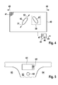
- the touch-sensitive surface has individual matrix elements 41, each of which can associate a touch with a position on the touch-sensitive surface. If now an operation in which a user has to reach to the right to reach the touch-sensitive surface 40, then a corresponding orientation of a touch by a finger from bottom left to right up, so that a corresponding touch panel 42 results. If use is made such that a user has to reach to the left with his left hand to reach the touch-sensitive surface 40, a corresponding touch pad will be formed from top left to bottom right according to the touch pad 43 in FIG FIG. 4 result.
- a touch can be evaluated by an evaluation unit 44 and a function triggered in response to a touch from the left or from the right.
- a contact is assigned from a solid angle region to the left of the touch-sensitive surface, ie in the direction of arrow 45, while a contact field 43 is assigned a solid angle region to the right, that is to say in the direction of arrow 46, to the right of the touch-sensitive surface 40.
- the evaluation unit 44 has a computing device 47, wherein the assignment to respective solid angle ranges is stored in a memory unit 48. Via a control line 49, a respective operation to be performed can be forwarded to an electrical device or to further components.
- a Operation can be carried out in such a way that a triggering of a function is assigned to a triggering field 50 when a touch within the triggering field 50 is detected. Furthermore, however, similar to a slider, a linear movement can be detected and used for function control, that is, for example, a linear movement in the direction of arrow 51 or 52.
- FIG. 5 An exemplary arrangement of a rotary control 60 is shown in FIG FIG. 5 shown.
- the rotary control is in this case arranged adjacent to a display surface 61 in a center console 62 of a vehicle. Left of the center console, a driver's seat 63 is provided, while right from the center console 62, a passenger seat 64 is provided.
- various vehicle functions such as climate functions, a seat adjustment or a navigation function can be displayed. Further, it is also possible to represent entertainment functions such as a selection of a radio program or an output of a television program.
- the display 61 may be designed such that a different image is visible from the driver's seat 63 and from the passenger's seat 64, respectively.
- a selection of functions in the display 61 via the rotary control 60 is assigned to the position of the passenger 64 or the position of the driver 63. For example, a selection may be made of individual function fields 65 shown in the display 61.
Landscapes
- Engineering & Computer Science (AREA)
- Chemical & Material Sciences (AREA)
- Combustion & Propulsion (AREA)
- Transportation (AREA)
- Mechanical Engineering (AREA)
- Input From Keyboards Or The Like (AREA)
- Rotary Switch, Piano Key Switch, And Lever Switch (AREA)
- Mechanical Control Devices (AREA)
Applications Claiming Priority (1)
| Application Number | Priority Date | Filing Date | Title |
|---|---|---|---|
| DE102008044332A DE102008044332A1 (de) | 2008-12-04 | 2008-12-04 | Bedieneinrichtung und Verfahren zur Bedienung |
Publications (2)
| Publication Number | Publication Date |
|---|---|
| EP2193953A2 true EP2193953A2 (fr) | 2010-06-09 |
| EP2193953A3 EP2193953A3 (fr) | 2012-01-04 |
Family
ID=41716570
Family Applications (1)
| Application Number | Title | Priority Date | Filing Date |
|---|---|---|---|
| EP09173407A Withdrawn EP2193953A3 (fr) | 2008-12-04 | 2009-10-19 | Dispositif de commande et procédé de commande |
Country Status (3)
| Country | Link |
|---|---|
| EP (1) | EP2193953A3 (fr) |
| CN (1) | CN101898515A (fr) |
| DE (1) | DE102008044332A1 (fr) |
Cited By (4)
| Publication number | Priority date | Publication date | Assignee | Title |
|---|---|---|---|---|
| WO2015090537A1 (fr) * | 2013-12-18 | 2015-06-25 | Diehl Ako Stiftung & Co. Kg | Bouton rotatif d'actionnement avec agencement détecteur |
| WO2018103984A1 (fr) * | 2016-12-09 | 2018-06-14 | Zf Friedrichshafen Ag | Moyen de commande pour un système d'info-divertissement d'un véhicule automobile, procédé permettant de déterminer l'endroit où se trouve un opérateur d'un tel élément de commande |
| AT519401A1 (de) * | 2016-11-23 | 2018-06-15 | Keba Ag | Bedienelement für eine elektrisch gesteuerte Maschine, sowie ein Verfahren zur Eingabe eines Befehls in die Steuerung der elektrisch gesteuerten Maschine |
| DE102020132554A1 (de) | 2020-12-08 | 2022-06-09 | Valeo Schalter Und Sensoren Gmbh | Bedieneinrichtung, Mittelkonsole und Verfahren zum Bestimmen einer Zulässigkeit einer bestimmten Betätigung eines Bedienelements einer Bedieneinrichtung |
Families Citing this family (5)
| Publication number | Priority date | Publication date | Assignee | Title |
|---|---|---|---|---|
| DE102012018291B4 (de) * | 2012-09-14 | 2016-05-04 | Audi Ag | Bedienvorrichtung für eine Funktionseinrichtung eines Kraftfahrzeugs |
| CN106183815B (zh) * | 2016-08-10 | 2018-05-25 | 天津华夏联盛汽车部件有限公司 | 一种副仪表板右延伸板总成 |
| DE102022115767A1 (de) * | 2022-06-24 | 2024-01-18 | Signata GmbH | Verfahren zur Bedienererkennung an einem rotatorischen Bedienelement |
| DE102023121273B4 (de) | 2023-08-09 | 2025-04-17 | Audi Aktiengesellschaft | Vorrichtung und Verfahren zum eingabeabhängigen Auslösen einer Bedienfunktion |
| CN118478794A (zh) * | 2024-05-08 | 2024-08-13 | 浙江吉利控股集团有限公司 | 车辆功能分区控制方法、装置、设备、介质、产品及车辆 |
Citations (1)
| Publication number | Priority date | Publication date | Assignee | Title |
|---|---|---|---|---|
| DE10337852A1 (de) | 2003-08-18 | 2005-03-17 | Robert Bosch Gmbh | Fahrzeugsystem |
Family Cites Families (5)
| Publication number | Priority date | Publication date | Assignee | Title |
|---|---|---|---|---|
| JP2005096515A (ja) * | 2003-09-22 | 2005-04-14 | Alps Electric Co Ltd | 車載用入力装置 |
| DE102005035111A1 (de) * | 2005-07-27 | 2006-09-21 | Daimlerchrysler Ag | Bedien- und Anzeigesystem für ein Fahrzeug |
| JP2007196742A (ja) * | 2006-01-24 | 2007-08-09 | Tokai Rika Co Ltd | 入力装置 |
| JP4888063B2 (ja) * | 2006-11-08 | 2012-02-29 | 株式会社デンソー | 手動操作装置 |
| DE102007015878A1 (de) * | 2007-04-02 | 2008-10-09 | Robert Bosch Gmbh | Bedieneinheit und Bedienverfahren |
-
2008
- 2008-12-04 DE DE102008044332A patent/DE102008044332A1/de not_active Withdrawn
-
2009
- 2009-10-19 EP EP09173407A patent/EP2193953A3/fr not_active Withdrawn
- 2009-12-03 CN CN2009102536012A patent/CN101898515A/zh active Pending
Patent Citations (1)
| Publication number | Priority date | Publication date | Assignee | Title |
|---|---|---|---|---|
| DE10337852A1 (de) | 2003-08-18 | 2005-03-17 | Robert Bosch Gmbh | Fahrzeugsystem |
Cited By (9)
| Publication number | Priority date | Publication date | Assignee | Title |
|---|---|---|---|---|
| WO2015090537A1 (fr) * | 2013-12-18 | 2015-06-25 | Diehl Ako Stiftung & Co. Kg | Bouton rotatif d'actionnement avec agencement détecteur |
| US20160294387A1 (en) * | 2013-12-18 | 2016-10-06 | Diehl Ako Stiftung & Co. Kg | Operating device and appliance having the device |
| US10050622B2 (en) * | 2013-12-18 | 2018-08-14 | Diehl Ako Stiftung & Co. Kg | Operating device and appliance having the device |
| DE102013021093B4 (de) | 2013-12-18 | 2023-11-30 | Diehl Ako Stiftung & Co. Kg | Bedienvorrichtung |
| AT519401A1 (de) * | 2016-11-23 | 2018-06-15 | Keba Ag | Bedienelement für eine elektrisch gesteuerte Maschine, sowie ein Verfahren zur Eingabe eines Befehls in die Steuerung der elektrisch gesteuerten Maschine |
| AT519401B1 (de) * | 2016-11-23 | 2018-08-15 | Keba Ag | Bedienelement für eine elektrisch gesteuerte Maschine, sowie ein Verfahren zur Eingabe eines Befehls in die Steuerung der elektrisch gesteuerten Maschine |
| US10802619B2 (en) | 2016-11-23 | 2020-10-13 | Keba Ag | Operating element for an electrically controlled machine |
| WO2018103984A1 (fr) * | 2016-12-09 | 2018-06-14 | Zf Friedrichshafen Ag | Moyen de commande pour un système d'info-divertissement d'un véhicule automobile, procédé permettant de déterminer l'endroit où se trouve un opérateur d'un tel élément de commande |
| DE102020132554A1 (de) | 2020-12-08 | 2022-06-09 | Valeo Schalter Und Sensoren Gmbh | Bedieneinrichtung, Mittelkonsole und Verfahren zum Bestimmen einer Zulässigkeit einer bestimmten Betätigung eines Bedienelements einer Bedieneinrichtung |
Also Published As
| Publication number | Publication date |
|---|---|
| CN101898515A (zh) | 2010-12-01 |
| DE102008044332A1 (de) | 2010-06-10 |
| EP2193953A3 (fr) | 2012-01-04 |
Similar Documents
| Publication | Publication Date | Title |
|---|---|---|
| EP2193953A2 (fr) | Dispositif de commande et procédé de commande | |
| EP2822812B1 (fr) | Véhicule automobile avec un miroir électronique | |
| EP1977926B1 (fr) | Unité et procédé de commande | |
| EP2059407B1 (fr) | Procede pour commander des equipements d'un vehicule et dispositif de commande pour de tels equipements | |
| EP2121372B1 (fr) | Dispositif d'affichage et de commande pouvant etre active sans contact | |
| WO2006074712A2 (fr) | Dispositif d'entree de donnees | |
| DE102012214017A1 (de) | System zum verhindern des lösens eines blickes zur verwendungwährend des fahrens eines fahrzeugs | |
| DE102006028046A1 (de) | Kombinierte Anzeige- und Bedienvorrichtung für ein Kraftfahrzeug | |
| EP1517224A2 (fr) | Dispositif d'affichage sensible au toucher | |
| DE102008023405B4 (de) | Kraftfahrzeug mit einem Display sowie Verfahren zum Betrieb eines Kraftfahrzeuges mit einem Display | |
| DE102016200022A1 (de) | Vorrichtung zum Schalten in einem Kraftfahrzeug | |
| EP3243688B1 (fr) | Procédé et dispositif d'attribution d'instructions de commande dans un véhicule automobile et véhicule automobile | |
| DE102017217199A1 (de) | System zur unterstützung der betätigung von fahrzeugausstattungs-einrichtungen | |
| EP1194309A1 (fr) | Dispositif d'affichage, notamment pour automobile | |
| EP3254172A1 (fr) | Détermination d'une position d'un objet étranger à un véhicule dans un véhicule | |
| DE102010018637B4 (de) | Bedienvorrichtung in einem Straßenfahrzeug | |
| EP2137022B1 (fr) | Système d'information et procédé destiné à fournir des informations dans un véhicule à moteur avec une exploitabilité améliorée | |
| DE102012011177A1 (de) | Verfahren zur Bedienung von Funktionen einesFahrzeuges sowie entsprechende Vorrichtung | |
| DE102015115362B4 (de) | Erfassungsvorrichtung für ein Kraftfahrzeug sowie Kraftfahrzeug | |
| DE112014006474T5 (de) | Betätigungsvorrichtung | |
| WO2014108152A2 (fr) | Interface utilisateur pour véhicule automobile dotée d'un élément de commande permettant de détecter une action de commande | |
| DE102009037401A1 (de) | Fahrzeug mit einer Bedieneinrichtung | |
| WO2014067774A1 (fr) | Procédé et dispositif de fonctionnement d'un système d'entrée | |
| DE102009039114B4 (de) | Bedienvorrichtung für ein Fahrzeug | |
| EP4043263B1 (fr) | Procédé de commande ds fonctions de véhicule |
Legal Events
| Date | Code | Title | Description |
|---|---|---|---|
| PUAI | Public reference made under article 153(3) epc to a published international application that has entered the european phase |
Free format text: ORIGINAL CODE: 0009012 |
|
| AK | Designated contracting states |
Kind code of ref document: A2 Designated state(s): AT BE BG CH CY CZ DE DK EE ES FI FR GB GR HR HU IE IS IT LI LT LU LV MC MK MT NL NO PL PT RO SE SI SK SM TR |
|
| AX | Request for extension of the european patent |
Extension state: AL BA RS |
|
| PUAL | Search report despatched |
Free format text: ORIGINAL CODE: 0009013 |
|
| AK | Designated contracting states |
Kind code of ref document: A3 Designated state(s): AT BE BG CH CY CZ DE DK EE ES FI FR GB GR HR HU IE IS IT LI LT LU LV MC MK MT NL NO PL PT RO SE SI SK SM TR |
|
| AX | Request for extension of the european patent |
Extension state: AL BA RS |
|
| RIC1 | Information provided on ipc code assigned before grant |
Ipc: B60K 37/06 20060101AFI20111130BHEP |
|
| 17P | Request for examination filed |
Effective date: 20120704 |
|
| STAA | Information on the status of an ep patent application or granted ep patent |
Free format text: STATUS: THE APPLICATION IS DEEMED TO BE WITHDRAWN |
|
| 18D | Application deemed to be withdrawn |
Effective date: 20120705 |