EP2194200A2 - Liaison de raccordement pour le raccordement horizontal de composants sur un mur - Google Patents
Liaison de raccordement pour le raccordement horizontal de composants sur un mur Download PDFInfo
- Publication number
- EP2194200A2 EP2194200A2 EP09014139A EP09014139A EP2194200A2 EP 2194200 A2 EP2194200 A2 EP 2194200A2 EP 09014139 A EP09014139 A EP 09014139A EP 09014139 A EP09014139 A EP 09014139A EP 2194200 A2 EP2194200 A2 EP 2194200A2
- Authority
- EP
- European Patent Office
- Prior art keywords
- connection
- component
- wall
- box
- stop
- Prior art date
- Legal status (The legal status is an assumption and is not a legal conclusion. Google has not performed a legal analysis and makes no representation as to the accuracy of the status listed.)
- Withdrawn
Links
Images


Classifications
-
- E—FIXED CONSTRUCTIONS
- E04—BUILDING
- E04B—GENERAL BUILDING CONSTRUCTIONS; WALLS, e.g. PARTITIONS; ROOFS; FLOORS; CEILINGS; INSULATION OR OTHER PROTECTION OF BUILDINGS
- E04B1/00—Constructions in general; Structures which are not restricted either to walls, e.g. partitions, or floors or ceilings or roofs
- E04B1/003—Balconies; Decks
Definitions
- the invention relates to a connection according to the preamble of claim 1 for horizontal connection of a particular plate-shaped component, such as a balcony slab, to a wall, in particular a building exterior wall, with a wall to be fastened to the stop element and to be determined with a component to be connected to the holding element.
- a particular plate-shaped component such as a balcony slab
- the invention relates to a component, in particular a plate-shaped component, for horizontal connection to a wall, in particular a building exterior wall, by means of at least one connection according to the invention, wherein the holding element of the connection connection in the lower, front region of the component with respect to the wall is.
- the invention further relates to a method for the horizontal connection of a particular plate-shaped component to a wall, in particular a building exterior wall, using at least one connection according to the invention.
- the invention is based on the object to further develop a connection connection of the type mentioned in that they can be mounted without additional installation effort in the assembly movement required for mounting said components. Furthermore, an easy-to-install component and a corresponding assembly method should be specified.
- a connection connection for the horizontal connection of a particular plate-shaped component, such as a balcony slab, to a wall, in particular a building exterior wall, with a stop element to be fastened to the wall and a holding element to be fastened to the component to be connected is characterized in that the stop element is in the mounted state has projecting structure directed away from the wall, and that the holding element has a box-like structure which is open at least on one side and whose one side wall has a slot-shaped opening which opens towards the open box side, with which the holding element engages over the protruding structure of the stop element during assembly of the component, so that from the open box side a securing element for horizontal connection of the holding element and thus of the component to the projecting structure of the stop element can be arranged and / or handled.
- An inventive component in particular in plate form, is designed for horizontal connection to a wall, in particular a building exterior wall, by means of at least one connection according to the invention, wherein the holding element of the connection connection in the lower, front region of the component relative to the wall is arranged to cooperate with a wall-mounted stop member of the connection connection.
- An inventive method for horizontal connection of a particular plate-shaped component to a wall, in particular a building outer wall, wherein the component is placed on supports for receiving the vertical load is characterized by using a terminal connection according to the invention or a component according to the invention, wherein the component with the slot-shaped Recess of the retaining element, the projecting structure of the stop element is mounted vertically above from above.
- connection connection provides that the projecting structure has a threaded portion on which the securing element can be screwed in the manner of a lock nut to create a flat, non-positive connection between the stop element and the holding element.
- the stop element preferably has a stop plate to be mounted parallel to the wall, against which the side wall of the holding element rests flat after attachment of the securing element.
- an opening for a threaded rod may be provided, which forms the projecting structure, wherein the opening is preferably formed as a slot, so that the projecting structure with respect to the remaining stop element in the unloaded state before connection of the component is movable, in particular in one direction parallel to the wall level to compensate for mounting tolerances.
- the threaded rod can be secured against falling out of the stop element by a terminal widening, in particular a screw head.
- connection connection provides that the box-like structure - hereinafter alternatively referred to as "mounting box” - or at least the above-mentioned side wall is designed so stiff that it receives horizontal forces perpendicular and parallel to the wall.
- connection according to the invention provides that for closing the box-like structure on its open side a lid member and the box-like structure and / or on the lid member corresponding lid holding means are provided, in particular screw, Klipsstoff, magnetic holding means, adhesive or the like, to improve in this way in particular the aesthetics of the connection connection according to the invention.
- the retaining element can furthermore have a reinforcement structure for connection to the component.
- a first development of the method according to the invention is characterized in that prior to assembly of the component, the securing element is attached to the projecting structure, wherein a distance of the securing element from the remaining stop element and in particular from the stop plate at least selected greater than a wall thickness of the side wall of the box-like structure becomes.
- the fuse element can thus not be lost during assembly and then - in particular in the case of training as a lock nut - only to be tightened, which can be done in a simple manner through the opening of the mounting box.
- the fuse element is mounted after assembly of the component from below through the open box side of the projecting structure.
- the securing element is displaced relative to the projecting structure, in particular screwed onto this, to a frictional connection between the holding element, in particular the outside of the side wall of the box-like structure, and the stop element, in particular the stop plate mentioned above , to accomplish.
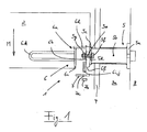
- FIG. 1 shows a longitudinal section through a connection connection 1 according to the invention for the horizontal connection of a plate-shaped component in the form of a balcony slab 2 to a supporting outer wall 3 of a building, the latter as shown in FIG. 1 has an additional insulating layer 3a and an outer plaster layer 4.
- the connection connection 1 comprises a substantially hollow-cylindrical stop element 5, which is fastened in a suitable manner (not shown) to the building exterior wall 3, for example screwed on.
- the stop element 5 has a corresponding mounting flange 5a at its end facing the building.
- the interior 5b of the stop element 5 is hollow, and at its end facing away from the building, the stop element 5 carries a stop plate 5c.
- the stop plate 5c has an opening 5d, which in the present case is designed as a slot through which a threaded rod 5e is guided outwardly from the interior 5b of the stop element 5, ie away from the building.
- the threaded rod 5e is secured by a widening in the form of a screw head 5f against falling out of the opening 5d and is with respect to the remaining stop member 5 is a projecting structure, which is opposite the stop plate 5c protrudes.
- the connection connection 1 has a holding element 6, which is arranged on the front edge of the plate-shaped component 2, which is lower relative to the building.
- the holding element 6 comprises an upwardly and downwardly open box-type or box-like structure 6a (assembly box) with a first outer side wall 6b relative to the plate-shaped component 2 and a second inner side wall 6c relative to the plate-shaped component 2.
- the first side wall 6b and the second side wall 6c are arranged parallel to one another and connected in their respective upper regions by means of transverse struts 6d.
- the outer side wall 6b has a central, slot-shaped recess 6e, which in particular in the FIG. 3 easy to recognize.
- the slot-shaped recess 6e opens to the free, lower edge 6f of the outer side wall 6b and there has a mutual widening 6g.
- further threaded rods 6i, 6j are mounted on the outer side wall 6b from the inside, which extend parallel to the side walls 6b, 6c and project downwards beyond the box-like structure 6a.
- the holding element 6 On the side of the inner side wall 6c facing the plate-shaped component 2, the holding element 6 has a double, bow-shaped reinforcing structure 6k, which serves for connection to the plate-shaped component 2, in particular for pouring into the plate-shaped component 2 during its production.
- a securing element 5g in the form of a lock nut is arranged or screwed on at its free end (see FIG. 1 ).
- the securing member 5g serves to frictionally abut the stopper plate 5c of the stopper member 5 and the outer side of the outer side wall 6b of the holding member 6 to provide for the horizontal connection of the plate-shaped member 2 to the building wall 3, if that 5g displaced (tightened) accordingly on the threaded rod 5e, which will be discussed in more detail below.
- a cover element 7 is furthermore provided, which is designed in the manner of a plate which has openings 7a for attachment to the threaded rods 6i, 6j.
- securing elements in the form of nuts 7b are provided which are screwed onto the threaded rods 6i, 6j accordingly.
- the first side wall 6b has a relation to the second side wall 6c smaller extension downwards, that is parallel to the wall plane of the building wall 3, this minimum dimension preferably corresponds exactly to the plate thickness of the lid member 7.
- the openings 7a are arranged eccentrically in the cover element 7, so that this rests after its mounting on the free lower edge of the first side wall 6b, while on the other hand is aligned with the lower edge of the second side wall 6c.
- FIG. 4 is a preferred use of the terminal connection 1 according to the FIGS. 1 to 3 shown. It is the subsequent installation of balcony slabs 2 vertically above one another with horizontal connection to an existing building wall 3, to which, if necessary, a new insulation layer 3a and a plaster layer 4 were applied.
- the details of the terminal connection 1 have been described above with reference to FIGS. 1 to 3 already described in detail, so that in the present case is not to be re-entered.
- At least two such connection connections 1 are used on each balcony slab 2, which are spaced as far apart as possible in order to form a corresponding force pair with a lever arm.
- the balcony slabs 2 are mounted vertically one above the other, wherein the vertical load is absorbed by supports 8.
- the balcony slabs 2 are preferably mounted from above according to the mounting direction symbolized by the arrow M (cf. FIG. 1 ). This mode of operation is optimally supported by the connection connection 1 according to the invention, which will now be discussed in more detail.
- the stopper member 5 is fixed to the wall 3.
- the insulation 3a and the plaster 4 is then applied, so that the stop plate 5c protrudes from the plaster layer 4 by, for example, about 2 cm.
- the threaded rod protrudes, for example, about 4 cm from the stop plate 5c.
- the securing element 5g is already arranged on the threaded rod 5e, but between the securing element 5g and the stop plate 5c sufficient space for the outer side wall 6b of the support member 6, that is, the wall thickness must remain.
- the securing element 5g can also be subsequently applied to the threaded rod 5e.
- the balcony slab 2 is approximated from above with its holding element 6 to the wall 3 and the stop element 5 that the outer side wall 6b with her Slit 6e engages the threaded rod 5e, wherein optionally the already applied securing element 5g is then arranged in the interior 6h of the box-like structure or mounting box 6a.
- the securing element 5g is then arranged in the interior 6h of the box-like structure or mounting box 6a.
- height adjustment of the plate-shaped member 2 is possible.
- the closing of the mounting box 6a down is not limited to the provision of the present case only by way of example described screw cap, but can be realized by providing a correspondingly formed cover member 7 by gluing, Verklipsen, magnetic bonding or the like.
- the opening 5d for the threaded rod 5e in the stop plate 5c is preferably - as already mentioned - formed as a slot, which in particular in the plane of the FIG. 1 is oriented so that mounting tolerances of the stop elements 5 on the building wall 3 and the holding elements 6 on the plate-shaped component 2 can be compensated.
- the mounting box 6a and in particular its outer side wall 6b is formed so stiff that it can safely absorb the resulting forces, that is horizontal forces perpendicular and parallel to the building. These forces are then introduced into the plate-shaped component 2 via the reinforcement 6k.
- the vertical slot is 6e in the mounting box 6a thus allows the already mentioned recording of mounting tolerances on the one hand and vertical thermal movements of the plate-shaped components 2 on the other hand, without forcing forces build up, said thermal movements therefore stir that the supports slightly lengthen or shorten with temperature changes.
Landscapes
- Engineering & Computer Science (AREA)
- Architecture (AREA)
- Physics & Mathematics (AREA)
- Electromagnetism (AREA)
- Civil Engineering (AREA)
- Structural Engineering (AREA)
- Finishing Walls (AREA)
- Connection Of Plates (AREA)
Applications Claiming Priority (1)
| Application Number | Priority Date | Filing Date | Title |
|---|---|---|---|
| DE200810061008 DE102008061008A1 (de) | 2008-12-08 | 2008-12-08 | Anschlussverbindung zum horizontalen Anschließen von Bauteilen an eine Wand |
Publications (2)
| Publication Number | Publication Date |
|---|---|
| EP2194200A2 true EP2194200A2 (fr) | 2010-06-09 |
| EP2194200A3 EP2194200A3 (fr) | 2012-08-01 |
Family
ID=41716632
Family Applications (1)
| Application Number | Title | Priority Date | Filing Date |
|---|---|---|---|
| EP09014139A Withdrawn EP2194200A3 (fr) | 2008-12-08 | 2009-11-11 | Liaison de raccordement pour le raccordement horizontal de composants sur un mur |
Country Status (2)
| Country | Link |
|---|---|
| EP (1) | EP2194200A3 (fr) |
| DE (1) | DE102008061008A1 (fr) |
Cited By (2)
| Publication number | Priority date | Publication date | Assignee | Title |
|---|---|---|---|---|
| EP2660401A3 (fr) * | 2012-05-02 | 2014-02-26 | R-Group Finland OY | Charnière pour balcon |
| CN114525891A (zh) * | 2022-02-24 | 2022-05-24 | 山东长箭建设集团有限公司 | 一种装配式建筑墙连接结构 |
Families Citing this family (3)
| Publication number | Priority date | Publication date | Assignee | Title |
|---|---|---|---|---|
| DE102015016450A1 (de) | 2015-12-21 | 2017-06-22 | Frank Herrmann | Vorrichtung zum Anschließen eines auskragenden Bauteils, insbesondere eines Balkons oder eines Vordachs, sowie ein diese Vorrichtung verwendendes Bauteil |
| DE202015008660U1 (de) | 2015-12-21 | 2017-03-22 | Frank Herrmann | Vorrichtung zum Anschließen eines auskragenden Bauteils, insbesondere eines Balkons oder eines Vordachs, sowie ein diese Vorrichtung verwendendes Bauteils |
| CN114164951A (zh) * | 2021-12-02 | 2022-03-11 | 江苏和天下节能科技股份有限公司 | 一种便于稳定起吊安装的混凝土预制阳台 |
Family Cites Families (5)
| Publication number | Priority date | Publication date | Assignee | Title |
|---|---|---|---|---|
| DE6939021U (de) * | 1969-10-06 | 1970-03-19 | Bruno Heibges | Befestigungseinrichtung fuer betonfertigteile |
| DE2732183C3 (de) * | 1977-07-15 | 1981-06-04 | Doblin, Robert, Dipl.-Ing., 4000 Düsseldorf | Verbindung zweier mit ihren Stirnflächen einander gegenüberliegenden Stahlbetonteile |
| US5230191A (en) * | 1991-05-28 | 1993-07-27 | Paul Mayrand | Precast insulated concrete panel for prefabricated building structure |
| DE29805143U1 (de) * | 1998-03-23 | 1998-07-16 | Nicolai, Karl-Friedrich, 24146 Kiel | Balkonanlage mit einem Gebäudeanschluß |
| FI20002303L (fi) * | 2000-10-18 | 2002-04-19 | Teraespeikko Oy | Konsoli rakenneosan, kuten betonielementtipalkin, tukemiseksi betonipilariin tai vastaavaan rakennuksen tukirakenteeseen |
-
2008
- 2008-12-08 DE DE200810061008 patent/DE102008061008A1/de not_active Withdrawn
-
2009
- 2009-11-11 EP EP09014139A patent/EP2194200A3/fr not_active Withdrawn
Cited By (3)
| Publication number | Priority date | Publication date | Assignee | Title |
|---|---|---|---|---|
| EP2660401A3 (fr) * | 2012-05-02 | 2014-02-26 | R-Group Finland OY | Charnière pour balcon |
| CN114525891A (zh) * | 2022-02-24 | 2022-05-24 | 山东长箭建设集团有限公司 | 一种装配式建筑墙连接结构 |
| CN114525891B (zh) * | 2022-02-24 | 2024-01-19 | 山东长箭建设集团有限公司 | 一种装配式建筑墙连接结构 |
Also Published As
| Publication number | Publication date |
|---|---|
| DE102008061008A1 (de) | 2010-07-01 |
| EP2194200A3 (fr) | 2012-08-01 |
Similar Documents
| Publication | Publication Date | Title |
|---|---|---|
| EP3384567B1 (fr) | Châssis pour armoire électrique | |
| DE102008061008A1 (de) | Anschlussverbindung zum horizontalen Anschließen von Bauteilen an eine Wand | |
| EP1868885B1 (fr) | Element structurel d'un avion comportant une cavite et un element de drainage | |
| EP2725159A1 (fr) | Dispositif de support, procédé de fabrication d'un dispositif de support et utilisation d'un dispositif de support au niveau d'un mur rideau | |
| DE202012010850U1 (de) | Verbundanker zur Bildung einer Betonplatteneinheit sowie mit diesem Verbundanker ausgestattete Betonplatteneinheit | |
| WO2012075996A1 (fr) | Profilé en u pour le montage serré d'une vitre garde-corps | |
| DE202021101776U1 (de) | Einrichtung zur nachträglichen thermisch isolierenden, kraftübertragenden Anbindung eines zweiten lastaufnehmenden Bauwerksteils an ein erstes lastaufnehmendes Bauwerksteil und Bauwerk mit einer solchen Einrichtung | |
| EP0306028B1 (fr) | Vantail de portail ou vantail de porte composé d'un ou de plusieurs parties et muni d'une serrure à barre | |
| DE202015008660U1 (de) | Vorrichtung zum Anschließen eines auskragenden Bauteils, insbesondere eines Balkons oder eines Vordachs, sowie ein diese Vorrichtung verwendendes Bauteils | |
| DE29922263U1 (de) | Aussparungskörper für Betondecken | |
| EP3091167A1 (fr) | Élément de fixation pour un cadre de fenêtre sur un plafond de bâtiment d'une construction, construction associée et procédé de fixation d'un cadre de fenêtre sur un plafond de bâtiment | |
| DE202021106979U1 (de) | Vorrichtung zur Aufhängung eines Balkons an einem Holzhaus | |
| DE3142122C2 (de) | Fensterelement für den nachträglichen Einbau in Bauwerksöffnungen | |
| DE19948467A1 (de) | Kasten für Rolläden oder dergleichen | |
| AT515974B1 (de) | System zum Aufbau einer Mauer mit einem Zaunfeld und/oder einer Tür | |
| EP2256756B1 (fr) | Transformateur électrique ou bobine d'arrêt électrique | |
| DE29501299U1 (de) | Montagerahmen für Sanitärkörper | |
| EP3296475A1 (fr) | Balcon et procédé de fabrication d'un tel balcon | |
| DE102008003071B4 (de) | Varioträger zur Montage an zwei vertikalen Trägerprofilen eines Racks sowie Montageverfahren | |
| AT513796B1 (de) | Leibungsrahmen und Verfahren zum Anordnen und Verbinden eines zweiteiligen Leibungsrahmens | |
| DE2526062C2 (de) | Vorrichtung zum Befestigen eines in eine Betonplatte einzubetonierenden Außenrahmens für ein Schiebefenster o. dgl. auf dem horizontalen Boden einer Form | |
| WO2024079771A1 (fr) | Cadre de revêtement métallique pour une porte | |
| DE19642214A1 (de) | Transport- und Verlegeanker für eine Doppel- oder Hohlwand | |
| AT510232A1 (de) | Wandelement | |
| EP0476275A1 (fr) | Disposition d'une pièce de brassage |
Legal Events
| Date | Code | Title | Description |
|---|---|---|---|
| PUAI | Public reference made under article 153(3) epc to a published international application that has entered the european phase |
Free format text: ORIGINAL CODE: 0009012 |
|
| AK | Designated contracting states |
Kind code of ref document: A2 Designated state(s): AT BE BG CH CY CZ DE DK EE ES FI FR GB GR HR HU IE IS IT LI LT LU LV MC MK MT NL NO PL PT RO SE SI SK SM TR |
|
| AX | Request for extension of the european patent |
Extension state: AL BA RS |
|
| PUAL | Search report despatched |
Free format text: ORIGINAL CODE: 0009013 |
|
| AK | Designated contracting states |
Kind code of ref document: A3 Designated state(s): AT BE BG CH CY CZ DE DK EE ES FI FR GB GR HR HU IE IS IT LI LT LU LV MC MK MT NL NO PL PT RO SE SI SK SM TR |
|
| AX | Request for extension of the european patent |
Extension state: AL BA RS |
|
| RIC1 | Information provided on ipc code assigned before grant |
Ipc: E04B 1/00 20060101AFI20120626BHEP |
|
| STAA | Information on the status of an ep patent application or granted ep patent |
Free format text: STATUS: THE APPLICATION IS DEEMED TO BE WITHDRAWN |
|
| 18D | Application deemed to be withdrawn |
Effective date: 20130202 |