EP3296475A1 - Balcon et procédé de fabrication d'un tel balcon - Google Patents
Balcon et procédé de fabrication d'un tel balcon Download PDFInfo
- Publication number
- EP3296475A1 EP3296475A1 EP17191931.9A EP17191931A EP3296475A1 EP 3296475 A1 EP3296475 A1 EP 3296475A1 EP 17191931 A EP17191931 A EP 17191931A EP 3296475 A1 EP3296475 A1 EP 3296475A1
- Authority
- EP
- European Patent Office
- Prior art keywords
- balcony
- cassette
- leg
- coupling
- base
- Prior art date
- Legal status (The legal status is an assumption and is not a legal conclusion. Google has not performed a legal analysis and makes no representation as to the accuracy of the status listed.)
- Granted
Links
Images





Classifications
-
- E—FIXED CONSTRUCTIONS
- E04—BUILDING
- E04B—GENERAL BUILDING CONSTRUCTIONS; WALLS, e.g. PARTITIONS; ROOFS; FLOORS; CEILINGS; INSULATION OR OTHER PROTECTION OF BUILDINGS
- E04B1/00—Constructions in general; Structures which are not restricted either to walls, e.g. partitions, or floors or ceilings or roofs
- E04B1/003—Balconies; Decks
-
- E—FIXED CONSTRUCTIONS
- E04—BUILDING
- E04D—ROOF COVERINGS; SKY-LIGHTS; GUTTERS; ROOF-WORKING TOOLS
- E04D11/00—Roof covering, as far as not restricted to features covered by only one of groups E04D1/00 - E04D9/00; Roof covering in ways not provided for by groups E04D1/00 - E04D9/00, e.g. built-up roofs, elevated load-supporting roof coverings
- E04D11/005—Supports for elevated load-supporting roof coverings
-
- E—FIXED CONSTRUCTIONS
- E04—BUILDING
- E04D—ROOF COVERINGS; SKY-LIGHTS; GUTTERS; ROOF-WORKING TOOLS
- E04D13/00—Special arrangements or devices in connection with roof coverings; Protection against birds; Roof drainage ; Sky-lights
- E04D13/04—Roof drainage; Drainage fittings in flat roofs, balconies or the like
- E04D13/0404—Drainage on the roof surface
- E04D13/0477—Underroof drainage layers
Definitions
- the invention further relates to a method for producing such a balcony.
- a balcony is a platform on a building that is above the ground level and protrudes from the building. It is usually edged by a parapet or railing.
- German utility model DE29920081U1 a balcony is described in which the balcony floor structure is constructed of a plurality along a common extension direction extended cassette elements.
- Each cassette element is shaped in cross-section perpendicular to the extension direction in such a way that it has a base which forms part of the balcony floor underside and that starting from the base at least one coupling leg with a coupling region spaced from the base for connecting adjacent cassette elements and / or to the support außteilbelags extends to the balcony floor structure.
- Each coupling region has a form-fitting section which extends along the direction of extension and via which adjacent cassette elements are connected to one another in a form-fitting manner.
- a disadvantage of this solution is that the positive connection portion of the cassette elements is designed such that to ensure a sufficiently stable statics of the balcony floor structure, the cassette elements must have a high degree of rigidity and resilience in itself. This requires certain material thicknesses of the cassette elements, which in turn has a correspondingly high weight result. The higher weight is associated with a greater effort during transport and installation.
- the object is achieved by a balcony having the features of claim 1 and by a method for producing such a balcony having the features of claim 11.
- the cassette elements, the carrier profile or both are formed from bent thin sheet and that in each case between the base and coupling leg of the cassette elements a coupling leg angle A of 60 to 70 degrees is formed.
- a thin sheet is made of a metal or a metal alloy, preferably of galvanized steel.
- the thickness of the thin sheet is preferably up to 3 millimeters, more preferably up to 2.5 millimeters, and most preferably 1 to 2 millimeters.
- Such a thin sheet can be easily processed by means of a forming tool, in particular a Abkanttechnikmaschines.
- the cassette elements formed from thin sheet significantly lighter than flat steel with material thicknesses well over 5 mm and formed of thin sheet by folding cassette elements are significantly cheaper than extruded aluminum profiles. As a result, these cassette elements are cheaper and easier to transport and assemble. Regularly, therefore, transport and installation of the entire balcony can be done by a single person without special lifting tools.
- the use of thin sheet is also very advantageous for the formation of the carrier profile.
- a uniform along the direction of extension of the coupling leg of the cassette element is inevitably achieved when the cassette element is made by folding a metal thin plate.
- the direction of extension of the cassette element is inevitably predetermined by the edge of the Abkanttechnikmaschines.
- chamfering used in the context of this invention is a bending process known from the forming technique.
- folding is used below.
- Bending is a well-known and established forming process usually for sufficiently thin sheets of metal or metal alloys. This process is easy to control and opens up a great variety of possible coupling legs. The folding can be done mostly at high speed. Depending on the precision of the forming tool, the processing results can be reliably reproduced down to the millimeter range. As a result, this forming technique is very well suited for the efficient production of cassette elements with coupling legs of this type.
- the aforementioned method enables a wide variety of geometries of the cassette elements. This in turn makes, for example, a prefabrication of balcony components in high quantities possible. This reduces both the production costs and the installation time for a balcony.
- opposite balcony floor pads which are structurally formed in opposite carrier profile frame sections, preferably extends an integrally formed cassette element along the extension direction already mentioned.
- the base of a cassette element has a width of preferably 10 to 100 centimeters, more preferably 15 to 70 centimeters and most preferably 20 to 30 centimeters perpendicular to the direction of extension, especially when using thin sheet.
- Each cassette element has at least one coupling leg. This is preferably arranged in the edge region of the base. However, there may also be a plurality of coupling legs per cassette element, in particular two, which extend at both edge regions of the base of the cassette element along the extension direction.
- a cassette member may include a coupling leg and another leg extending away from the base which does not perform a function of coupling adjacent cassette members.
- This further limb may be formed as an initial limb or as a limb which extends at a defined angle, for example substantially perpendicular, or curved at a varying angle away from the base of the cartridge elements.
- the further leg forms both a structural reinforcement for supporting the cassette element on the balcony floor support of the carrier profile frame and a lateral boundary of the base, to give this a tub function for guiding water, which passes from above to the cassette elements.
- Each coupling leg has a coupling region with a positive connection section for coupling adjacent cassette elements.
- Two such adjacent cassette elements are mechanically coupled to one another by means of the form-fitting sections of their coupling regions extending parallel along the extension direction.
- the form-fitting sections are designed such that a displacement of adjacent cassette elements is blocked transversely to the extension direction. In order to prevent a relative displacement of adjacent cassette elements along the extension direction, the use of less fixing means which block such a displacement is sufficient. This also reduces the installation effort.
- the balcony floor bottom formed from a plurality of coupled together via their form-fitting sections cassette elements part of the drainage system of the balcony.
- the balcony base structure formed from the cassette elements simultaneously fulfills the function of drainage in addition to the static requirements.
- the water that hits the balcony floor top comes towards the base of each cartridge element, which forms a drainage pan together with the legs extending away from the base, in particular the coupling legs, and can be there from, for example, by a deliberately provided during assembly minimal Guiding gradient in the direction of a carrier profile of the carrier profile frame.
- the carrier profiles in which passes the guided from the cassette elements water, structurally designed such that they have a water drainage section.
- the water can be introduced by means of a dewatering device, for example in the form of pipes or gutters in a usually existing building drainage system.
- the water can also be passed from here into a collecting container, for example from the carrier profile frame or from the base of a cassette element.
- the flooring is often out of balance to cause drainage of rainwater in a direction predetermined by the slope.
- a balcony user is not quite in balance, which can be detrimental in some situations.
- these dewatering solutions often provide additional dewatering devices, such as complex containment and piping systems.
- the balcony floor underside can form a balcony ceiling completely or partially.
- the balcony ceiling is the visible, uncovered part of the balcony floor bottom, which a viewer sees when he looks from below at the balcony above.
- the cassette elements which by means of their respective bases can form a large part of the balcony floor underside, can be designed in different colors or in a uniform manner. This allows a balcony ceiling to be designed freely in terms of its appearance. For example, if the balcony ceiling is white, the resulting balcony receives more light thanks to the increased light reflection.
- the dimensioning of the cassette elements, in particular transversely to their extension direction contributes to the visually structured appearance of the balcony ceiling. This can be dispensed with further measures, such as an additional cover provided for the design of the balcony ceiling. This can save time and costs for designing the balcony ceiling.
- the coupling leg can be configured as an overlapping leg or as an engagement leg.
- Each version of the coupling leg has a positive connection section. Viewed from the base of the cassette element, the form-fitting section is arranged on the upper side of the engaging leg and on the underside of the engaging leg. If an overlapping leg and an engagement leg are coupled together to connect two cassette elements, the overlapping leg engages over the engagement leg. As a result, the form-fitting sections touch on the underside of the overlapping leg and the upper side of the engaging leg. If a weight force acts on the overlapping leg from the base of the cassette element from above, the positive connection between the overlapping leg and the engaging leg is loaded by the weight force. On The balcony objects and / or persons generate such weight.
- a plurality of cassette elements each have at both ends of the base a coupling leg, wherein the one coupling leg is formed as Studentsgreifschenkel and the other coupling leg as Eingreifschenkel, and the positive connection to the form-fitting portions of adjacent cassette elements through the Coupling of the Studentsgreifschenkels a first cassette element with the engagement leg of a second cassette element is made.
- cassette elements In the majority of cassette elements, an overlapping leg and an engaging leg are present per cassette element. As a result, several adjacent cassette elements can be positively connected with each other. This is preferably used to form a coherent balcony floor structure of significantly more than two cassette elements. Due to this connectability of the cassette elements, the individual cassette elements can be relatively small compared to the total area of the balcony floor construction. This facilitates the transport of the balcony components and the installation of the balcony.
- the embodiments with a cassette element having an overlapping leg are advantageously characterized in that a parallel to the base of the cassette element extending portion of the Kochgreifschenkels forms with its top a floor covering support for a balcony floor covering.
- the size of the bearing surface of this Floor covering of the cassette element is determined at a given height of the cassette element, inter alia, by the coupling leg angle.
- the width of the floor covering support of the cassette element and the spacing thereof is selected from the base.
- the floor covering of the cassette element can be covered with a balcony floor covering, for example made of wood, plastic, concrete, stone, other materials or a combination thereof. These materials can be screwed, for example, with the floor covering of the cassette element. This connection and / or the weight of the balcony floor covering exerts an additional holding force on the positive connection of the form-fitting sections.
- the cassette elements could be folded out of thin sheet metal so that the floor covering support of the cassette element, viewed in a direction perpendicular to the direction of extension, extends continuously parallel to the base. As a result, the top of the cassette elements forms the balcony floor top.
- adjacent cassette elements are fastened together in their common form-fitting sections with fixing means.
- fixing means are suitable as fixing agents: adhesive, screws, nails, rivets soldering, welding, other fixers not mentioned here or combinations thereof.
- the adjacent cassette elements are riveted together.
- the Fixing adjacent cassette elements together fixes the previously established positions of adjacent cassette elements and prevents their displacement along or transversely to the extension direction of the cassette elements.
- the cassette elements fixed to one another preferably form the balcony base structure, which is preferably made only of thin sheet metal, which, in spite of the low material thickness, provides the load capacity required for building balconies despite the riveted, partially form-fitting sheet metal connection. If all adjacent cassette elements are connected to one another by means of fixing means, then individual cassette elements can neither be removed nor displaced.
- a balcony floor construction formed with such a balcony floor structure is stable and very light. Unlike some fixers, using rivets has the advantage that rivets can be drilled out. As a result, once fixed together cassette elements can be subsequently dismantled, if required, for example, for a repair replacement of a single cassette element.
- the coupling leg angle can be formed differently large.
- the embodiment described above with the coupling leg angle is characterized in that the coupling leg angle of each cassette element are the same size.
- each coupling leg has a first form-fitting section extending parallel to the base of the cassette element.
- This first form-fitting section is through the spaced in the coupling leg angle away from the base coupling leg of the base and oriented parallel to the base.
- the first positive-locking section is directed upwards, that is to say away from the base and oriented parallel to the base.
- the first form-fitting section of a coupling leg which is formed as an overlapping leg and which is opposite this first form-fitting section of the engaging leg, in turn, is oriented downwards, that is to say towards the base, and likewise aligned parallel to the base.
- the back of the leg fürgreifschenk is also oriented parallel to the base with the coupling leg material thickness and has viewed from the base upwards. This section at least partially forms a fixing agent section.
- the preceding embodiment is advantageously characterized in that, following the first positive-locking section, a second positive-locking section is formed, which extends angled or curved away from the first positive-locking section.
- the engagement leg of a cassette element hooks under the overlapping leg of another adjacent cassette element and the combination of the first mold closure section and the second form-fitting section forms an edge or a curve.
- this edge or curvature acts in the form-fitting section as a mechanical stop which limits the movement of adjacent cassette elements transversely to the extension direction.
- This mechanical stop facilitates the step-by-step assembly of adjacent cassette elements by first applying the overlapping leg with its second positive-locking section at an acute angle to the second positive-locking section of the engaging leg. Subsequently, this acute angle is reduced by a rotation of the cassette element with the overlapping leg about a rotation axis parallel to the extension direction to zero and thereby produces the positive connection of the form-fitting portions of the adjacent cassette elements.
- the second form-fitting section preferably extends at right angles away from the first form-fitting section. This represents a particularly easy to produce by bending of thin sheet variant of the angled form-fitting portion.
- the carrier profile frame encloses the balcony floor construction and the cassette elements extend integrally along their extension direction between opposite sections of the carrier profile frame. Since the cassette elements extend integrally along their direction of extension between opposite portions of the carrier profile frame, no further support elements for the cassette elements along their extension direction are required. This reduces the effort for balcony installation. Furthermore, the integrally extending cassette elements also serve as an aesthetic design element for the balcony design. This allows elaborate subsequent design measures of the balcony, for example in the form of Disguises are dispensed with. This reduces the time, material and cost of the balcony design.
- the enclosing of the balcony floor construction by the carrier profile frame also has the consequence that from the top of the balcony incident rainwater transported in the direction of the carrier profile frame and can be derived from there, for example by means of a conduit system.
- This line system is preferably formed from water drainage sections, which is designed as a structural component of the carrier profile frame forming carrier profiles. In this way, it is not necessary to provide components that are used solely for drainage of the balcony floor construction of the balcony.
- the balcony floor structure integrates so to say by its design, the drainage functionality at the same time to its static function.
- the bending claimed in the context of this invention is a bending process known from the forming technique. Subsequently, only the term of the Abkantens is used.
- the support profile frame forming carrier profiles are made of metal, a metal alloy, plastic or a combination of the aforementioned materials.
- the carrier profile frame is formed by the carrier profiles are assembled into a carrier profile frame and then connected together. This connection is permanent or detachable. Preference is given to a permanent connection of the carrier profiles to a carrier profile frame, for example by welding or soldering.
- Such carrier profiles are preferably formed as follows. Viewed in cross-section, such a carrier profile is shaped like a polygonal C with an opening. From the upper end of this opening extends an upper end portion, while extending from the lower end of the opening, a lower end portion. These two end portions extend substantially perpendicularly away from the carrier profile and are aligned parallel to each other. The lower end portion forms a balcony floor support of the carrier profile while the upper end portion forms a floor covering support of the support profile for a balcony floor covering, which is provided regularly as part of the balcony floor construction.
- the carrier profile frame is fastened by means of a holding system to a building wall.
- This holding system is designed with or without a vertical stand system. Without a stand system, the load is taken up by means of one or more cantilevers and possibly by additional, connected to the building wall or adjacent balconies trains, preferably made of metal.
- the design and operation of a cantilever is described above.
- the use of a stand system may be required for large balconies. In these cases, the stand system provides for a partial or complete absorption of the load capacity of the balcony.
- the cassette elements are made of metal in the form of thin sheet metal.
- a galvanized sheet steel is preferably formed as follows: The thin sheet is folded in a forming tool to form a cassette element. The extension direction of the forming edge of the forming tool thereby defines the extension direction of the cassette element.
- the cassette element has the following structure: viewed in cross section to its extension direction, the cassette element has a base. The base is after installation part of a balcony floor bottom.
- Composite cassette elements form with their respective base the complete balcony floor underside.
- the balcony floor underside can form a balcony ceiling completely or partially.
- the balcony ceiling is the visible, uncovered part of the balcony floor bottom, which a viewer sees when he looks from below at the balcony above.
- the thin sheet is folded so that extends away from the base at least one coupling leg along the extension direction. Between the base and coupling leg a coupling leg angle is formed.
- the coupling leg angle is 60 to 70 degrees.
- the coupling leg has a coupling area.
- the coupling region is arranged at a defined distance from the base. Preferably, the coupling region is arranged on the end remote from the base of the coupling leg.
- the coupling region of the coupling leg is in turn by the Abkantvorgang of the sheet preferably formed at least partially parallel to the base.
- the coupling region has a positive connection section.
- the form-fitting section preferably has a first and adjacent thereto a second form-fitting section.
- first form-fitting portion is formed parallel to the base as part of the coupling region.
- second positive locking portion is angled or bent in the direction of the base.
- the second form-fitting section preferably forms the termination of the coupling region.
- Such coupling legs are formed as so-called engaging leg or as over-limb.
- the first and second form-fitting portion of the engaging leg is respectively formed on the top side facing away from the base of the coupling leg.
- the first and second form-fitting section of the overlapping leg are respectively arranged on the base of the underside facing the coupling leg.
- the cassette element When viewed in cross-section, the cassette element preferably has a coupling leg formed as an overlapping leg at one end of the base and a coupling leg formed at the other end of the base of an engagement leg. Deviating from individual cassette elements can be provided, which are folded at the edge of the coupled cassette elements only with a trained as engaging leg coupling leg or only with a designed as an overlapping leg coupling leg.
- Adjacent cassette elements are connected to each other during assembly of the balcony floor construction by means of their adjacent form-fitting sections.
- the rear side of the first form-fitting section of the overlapping leg preferably forms a floor covering support of the cassette element and can therefore be used for laying a balcony floor covering which forms the visible balcony floor top side.
- a first folded cassette element of this type is inserted into the carrier profile frame so that it is on opposite sections of the balcony floor support of the Carrier profile frame rests. Preferably, these sections are oriented parallel to each other. However, this depends on the geometry of the balcony.
- a second cassette element is placed on the balcony floor support of the carrier profile frame.
- the first cassette member is preferably connected to the adjacent second cassette member as follows.
- the engagement leg of a cassette element hooks under the overlapping leg of another adjacent cassette element and the combination of the first mold closure section and the second form-fitting section forms an edge or a curve.
- this edge or curvature acts in the form-fitting section as a mechanical stop which limits the movement of adjacent cassette elements transversely to the extension direction.
- the stepwise mounting of adjacent cassette elements is facilitated by the Mattergreifschenkel is first applied with its second form-fitting portion at an acute angle to the second form-fitting portion of the engaging leg. Subsequently, this acute angle is reduced by a rotation of the cassette element with the overlapping leg about a rotation axis parallel to the extension direction to zero and thereby produces the positive connection of the form-fitting portions of the adjacent cassette elements.
- cassette elements are preferably inserted into the carrier profile frame and connected to one another until the area enclosed by the carrier profile frame is completely filled.
- the cassette elements are displaceable along the extension direction up to a certain point, so that they can be threaded into the carrier profile frame.
- the form-fitting interconnected cassette elements are fixed to the carrier profile frame and each other.
- fixation screws rivets, adhesives, other fixatives or a combination thereof are used. Rivets are preferably used for this purpose.
- a hole in the positive connection region of the cassette element is made by the thin sheet of both cassette elements after assembly and adjustment of the added cassette element. Immediately following the rivet is placed in this hole and the two cassette elements are riveted together in this way. A corresponding procedure is carried out for fixing the cassette elements on the carrier profile frame. Unlike some fixers, using rivets has the advantage that rivets can be drilled out. As a result, mutually fixed cassette elements can be subsequently dismantled, if necessary.
- a balcony floor covering is placed on the floor covering support of the carrier profile and the floor coverings of the adjacent cassette elements and fixed to the cassette elements.
- screws, nails or specially trained fixatives are used for this purpose.
- An advantage of this method is that many balcony components can be prefabricated, the transport of the balcony components is therefore easy and the final assembly is carried out to a balcony of a few people without special lifting equipment.
- the preceding method is preferably further developed in such a way that the carrier profiles forming the carrier profile frame are folded from thin sheet, a carrier profile strand being first folded from thin sheet, then a plurality of carrier profiles are mitred from the carrier profile strand and the plurality of carrier profiles become a carrier profile frame connected.
- the carrier profiles are preferably cut directly by miter cut to the required length or they are first cut to the required length and then the carrier profile mitred.
- the thin sheet used for folding consists of a metal or a metal alloy, preferably of steel.
- the thickness of the thin sheet is preferably up to 3 millimeters, more preferably up to 2.5 millimeters, and most preferably 1 to 2 millimeters.
- bevelled thin sheet for carrier profile frames results in a significant weight saving compared to many currently used carrier profile frames of thicker flat steel.
- the flat steel used regularly has two to three times greater material thickness, so that the components made of it have twice and three times the weight.
- the significantly lower weight compared to this results in lower costs for transport and assembly and thus lower costs.
- the preceding method is advantageously further developed in such a way that the plurality of carrier profiles are connected to the carrier profile frame by means of welding, soldering or other suitable method.
- MSG welding is used.
- metal welding with inert gases This is a welding process using inert gas.
- This shielding gas prevents oxidation of the weld after welding.
- the shielding gases used are argon, helium or other suitable shielding gases. This welding process is well established and well controlled.
- the advantage is that in particular the welds of cut galvanized steel sheets do not have to be reworked after welding, for example with mechanical methods and / or rust inhibitors.
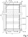
- FIG. 1 shows a preferred embodiment of a balcony in a schematic not to scale supervision of the balcony.
- the balcony has a rectangular in plan view carrier frame 10 with two long and two short sides.
- the carrier profile frame 10 is formed from a first carrier profile 12, a second carrier profile 14, a third carrier profile 16 and a fourth carrier profile 18.
- the carrier profiles 16 and 18 form the long sides of the carrier profile frame 10 which is rectangular in plan view.
- the short sides of the rectangular in the plan view carrier frame 10 are formed by the carrier profiles 12 and 14.
- An extension direction E runs between the carrier profiles 16 and 18.
- the extension direction E is parallel to the carrier profiles 12 and 14.
- the carrier profile frame 10 is connected to four vertical uprights 20.
- the four stands 20 are arranged at the four corners of the rectangle and serve to accommodate the loads taken from the balcony.
- the carrier profile frame 10 is connected by means of a holding system, not shown in this figure with a building wall 30.
- the Carrier profile frame 10 encloses a balcony floor structure 42.
- the balcony floor structure 42 has a plurality of interconnected cassette elements 50.
- Each cassette element 50 has a rectangular base with two long sides and two short sides. Along the long sides of a cassette element 50 extend one to two connecting sections not shown here, in which adjacent cassette elements partially overlap. These connection sections contain support sections and form-fitting sections.
- Each cassette element 50 extends integrally with the long sides along the extension direction E between the two carrier profiles 16 and 18. The long sides of the cassette elements 50 are thereby parallel to the short carrier profiles 12 and 14.
- the individual cassette elements 50 are positively connected to each other by means of form-fitting sections.
- the plurality of cassette members 50 are composed of an initial cassette member 52, a plurality of center cassette members 54 and a terminal cassette member 56.
- the structure of the carrier profile frame 10 and a cassette member 50 is shown in the other figures.
- FIG. 2 shows a cross-sectional view taken along the dotted line II-II FIG. 1 ,
- the parts of the carrier profile frame 10 shown here include the first carrier profile 12 and the second carrier profile 14 opposite thereto.
- each of the aforementioned carrier profiles is substantially shaped like a rectangular C with two long vertical sides, two short horizontal sides and one opening for receiving cassette elements 50. This opening is located on one of these two long sides and is arranged above the center of the carrier profile. From the upper end of this opening extends a horizontal upper end portion, and from the lower end of the opening extends a horizontal lower end portion. These two end portions extend substantially perpendicularly away from the carrier profile and are aligned parallel to each other.
- the lower end portion forms a Balcony floor support 44 while the upper end portion forms a floor covering support 461 of the carrier profile frame.
- the balcony floor covering 42 together with a balcony floor covering 46 a balcony floor construction 40.
- the balcony floor covering 46 usually consists of wood planks or flagstones, which are placed on the floor covering 461 of the support profile and / or the floor covering 462 of the cassette element.
- the wooden planks or stone slabs regularly extend in one piece along the extension direction E and can be fixed by means of screws (not illustrated here) to the floor covering support 461 of the support profile and / or the floor covering support 462 of the cassette element.
- the balcony floor construction 40 has a balcony floor top 401 and a balcony floor bottom 402.
- the balcony floor top 401 is formed from the top of the balcony floor covering 46 while the bottom of the balcony floor structure 42 forms the balcony floor bottom 402.
- the balcony floor bottom 402 is partially on the balcony floor support 44 of the surrounding carrier profiles.
- the balcony floor structure 42 is formed from a plurality of parallel adjacent cassette elements 50.
- an initial cassette element 52 is connected to a plurality of central cassette elements 54 and a closing cassette element 56 and fastened together with fixing means 72, preferably rivets, shown in this cross-sectional representation.
- the balcony floor structure 42 thus formed is likewise fastened to the carrier profile frame 10 with fixing means 72 (not shown here), preferably rivets.
- the visible from below section of the balcony floor bottom 402 forms the visible balcony floor 48, unless this section is covered by an additionally provided panel.
- FIG. 3 shows a carrier profile of the balcony in a perspective view.
- the carrier profile 12 is the result of a forming process of a thin sheet after six bending operations.
- On the balcony floor support 44 is when mounting the Balconies a portion of the balcony floor bottom 402 not shown in this figure placed on the floor covering support 461 of the support profile, a balcony floor covering 46 not shown here is placed in the balcony assembly.
- the lower U-shaped section is by folding a structural part of the C-shaped support profile on the short horizontal side. This U-shaped section forms a water drainage section 34.
- This water drainage section 34 continues over the other carrier profiles 14, 16, 18 in the entire carrier profile frame 10. He takes the trapped by the trough-shaped cassette elements 50 and guided into the carrier profiles water and dissipates it.
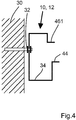
- FIG. 4 shows a cross-sectional view of the attached by means of a holding system on a building wall carrier profile of the balcony with four vertical uprights.
- the first carrier profile 12 has at least one hole in its vertical section in the present cross-sectional view. Through this hole, the support section 12 is connected by means of a holding system 32 comprising a screw and two washers with a likewise having a hole building wall.
- the load on this balcony is mainly absorbed by the vertical uprights.
- the holding system 32 is only used for laterally fixing the support profile frame 10 to the building wall 30.
- the water drainage section 34, the floor covering support 461 of the support profile and the balcony floor support 44 already applies accordingly in this figure.
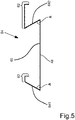
- FIG. 5 shows a central cassette element of the balcony in cross section.
- the middle cassette element 54 like the carrier profile 12, is the result of a forming process of a thin sheet after six bending operations.
- a pair of coupling legs 64 extend from a base 60 on the left edge of the base 60.
- An engagement leg 641 extends from the left edge of the base 60 and an overlapping leg 642 extends from the right edge.
- the engagement leg 66 and the overlapping leg 68 are at a coupling leg angle A of 60 to 70 degrees to the base 60 arranged.
- the end portions of engagement legs 641 and over-reach legs 642 each form a coupling region 62.
- Each coupling region 62 has two sections: a first section is parallel to the base as a result of the bending operation. As a result of the fold, a second section extends at right angles to this first section and towards the base 60 and forms the termination of the coupling region 62.
- the engagement limb 641, the overlapping limb 642 and its two sections of the coupling region 62 extend uniformly along the extension direction E as a result of the bending.
- the interaction of the coupling regions 62 of Eingreifschenkel 641 and Kochgreifschenkel 642 is together with FIG. 9 explained.
- the underside of the base 60 forms in particular the visible balcony floor 48 of the balcony floor underside.
- FIG. 6 shows a center cassette element of the balcony in a perspective view. It can be seen very clearly that the coupling leg angle A is constant along the extension direction E as a result of the bending.
- the engaging leg 641, the overlapping leg 642 and the two portions of the coupling portion 62 are formed as shown in FIG FIG. 2 and 5 described.
- FIG. 7 an initial cassette element of the balcony in perspective view.
- the initial cassette element 54 is the result of a forming process of a thin sheet after four bending operations.
- FIG. 6 extends here as a coupling leg 64 only the engaging legs 641 from the left edge of the base 60.
- the engaging leg 641 is formed as in FIG. 5 described.
- the other leg is an initial leg 66.
- the starting leg 66 is formed from a single section that extends substantially perpendicularly upwardly as viewed from the base. Along the extension direction E, the starting leg 66 extends uniformly due to the bending. It prevents the water impinging from above (eg rainwater) running uncontrollably in the direction of the carrier profile frame 12. This channeling of the water is part of the drainage system of the balcony. Further, the initial leg 66 increases the Torsional rigidity and thus the stability of the initial cassette element 52nd
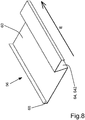
- FIG. 8 shows a closing cassette element 56 of the balcony in a perspective view.
- the final cassette element 56 is the result of a forming process of a thin sheet after four bending operations.
- the overlapping leg 642 is formed here as a coupling leg 64 on the right edge of the base 60.
- the overlapping leg 642 is formed as in FIG FIG. 5 described. The statements made there apply accordingly.
- the other leg disposed on the left edge of the base 60 is a terminator leg 68.
- the terminator leg 68 like the starting leg 66, is off FIG. 7 formed substantially vertically upwards. Everything about the beginning leg 66 off FIG. 7 The same applies accordingly to the end leg 68.
- FIG. 9 shows a balcony floor structure formed from three cassette elements 42 without balcony flooring.
- the balcony floor structure 42 is formed from the in FIG. 7 described initial cassette element 52, and in the Figures 5 and 6 described center cassette element 54 and the in FIG. 8 described final cassette element 56th in the FIGS. 5 to 8 The statements made apply accordingly and will therefore not be repeated here.
- These three cassette elements 52, 54, 56 are adjacent and partially overlapping each other. In overlapping areas, specially shaped form-fitting sections 70 are arranged.
- the structural design, in particular of the overlapping legs 642 and the engaging legs 641 is the result of the already mentioned Abkantungsreae and allows for balcony mounting the structure of the balcony floor structure 42 of form-fitting interconnected cassette elements 50.
- Each of the three cassette elements 52, 54, 56 has at least on the engaging legs 641st with a first form-fitting section 701 and a second form-fitting section 702 or via the overlapping leg 642 a first form-fitting portion 711 and a second form-fitting portion 712.
- the first form-fitting portion 701 of the engaging leg and the first form-fitting portion 711 of the overlapping leg are arranged at a defined distance and parallel to the base 60. Extending substantially perpendicularly therefrom, in the direction of the respective base 60, the second form-fitting section 702 of the engaging leg and the second form-fitting section 712 of the overlapping leg.
- the two form-fitting sections 702, 712 in each case form the conclusion of the engagement leg 641 or Studentsgreifschenkels 642.
- the four form-fitting sections 701, 711, 702, 712 extend as sections of the engaging legs 641 or Studentsgreifschenkel 642 due to Abkantungs myself also along the extension direction E.
- the base 60 rests as a component of the balcony floor underside in the carrier profile frame 10, not shown in this figure, on the balcony floor covering 44 there.
- each overlapping leg 642 has a floor covering pad 462 of the cassette element.
- This floor covering support 462 is arranged at a defined distance from the base 60 and formed from the upper side of the coupling region 62 of the overlapping limb 642 that is parallel to the base 60.
- On this floor covering support 462 of the cassette element is a, as in FIG. 2 described, not shown here balcony flooring can be placed.
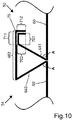
- FIG. 10 shows a positive connection of two adjacent cassette elements of the balcony in an enlarged view.
- the region which forms the positive connection between engagement limb 641 and overlapping limb 642 is hatched for clarity.
- the hatching does not constitute a component provided in addition to engaging legs 641 and overlapping legs 642. Hatched portions of overlapping legs 642 and engaging legs 641 are shown, which are positively coupled in a common form-fitting section 70.
- the common positive connection section 70 is formed from four individual Sections.
- the engagement leg 641 extends away from the base 60 of the starting cassette element 52 in a coupling leg angle A.
- the engagement leg 641 has the combination of the first form-fitting section 701 and the second form-fitting section 702 at its end section as the coupling section.
- the first positive engagement portion 701 is parallel to the base 60 and is directed away from the base 60 on the top of the engagement leg 641.
- the second form-fitting section 702 extends substantially perpendicularly away from the first form-fitting section 701 and extends in the direction of the base 60.
- the overlapping leg 642 extends away from the base 60 in a coupling leg angle A.
- the overlapping leg 642 has at its end section the first form-fitting section 711 and the adjoining second form-fitting section 712. Both form-fitting sections lie in the coupling region of the gripping leg 642.
- the first form-fitting section 711 runs parallel to the base 60 and is directed on the underside in the direction of the base 60.
- the second form-fitting section 712 extends substantially perpendicularly from the first form-fitting section 711 in the direction of the base 60.
- the two form-fitting sections 711 and 712 of the overlapping leg 642 come to lie on the two form-fitting sections 701 and 702 of the engaging leg 641 and form the common form-fitting section 70 with their contact surfaces out.
- each Goalgreifschenkel 642 at the top of its parallel to the base 60 extending portion of the flooring pad 462 of the cassette element.
- This floor covering support 462 is arranged at a defined distance from the base 60.
- a balcony floor covering not shown here, can be placed on the balcony, as already described in US Pat FIG. 2 and FIG. 9 mentioned.
Landscapes
- Engineering & Computer Science (AREA)
- Architecture (AREA)
- Civil Engineering (AREA)
- Structural Engineering (AREA)
- Physics & Mathematics (AREA)
- Electromagnetism (AREA)
- Steps, Ramps, And Handrails (AREA)
- Floor Finish (AREA)
Priority Applications (1)
| Application Number | Priority Date | Filing Date | Title |
|---|---|---|---|
| PL17191931T PL3296475T3 (pl) | 2016-09-19 | 2017-09-19 | Balkon i sposób wytwarzania takiego balkonu |
Applications Claiming Priority (1)
| Application Number | Priority Date | Filing Date | Title |
|---|---|---|---|
| DE102016117578 | 2016-09-19 |
Publications (2)
| Publication Number | Publication Date |
|---|---|
| EP3296475A1 true EP3296475A1 (fr) | 2018-03-21 |
| EP3296475B1 EP3296475B1 (fr) | 2020-08-05 |
Family
ID=59923269
Family Applications (1)
| Application Number | Title | Priority Date | Filing Date |
|---|---|---|---|
| EP17191931.9A Active EP3296475B1 (fr) | 2016-09-19 | 2017-09-19 | Balcon et procédé de fabrication d'un tel balcon |
Country Status (2)
| Country | Link |
|---|---|
| EP (1) | EP3296475B1 (fr) |
| PL (1) | PL3296475T3 (fr) |
Cited By (1)
| Publication number | Priority date | Publication date | Assignee | Title |
|---|---|---|---|---|
| CN113775043A (zh) * | 2021-10-12 | 2021-12-10 | 福建省建融工程建设有限公司 | 一种建筑阳台防护结构 |
Citations (3)
| Publication number | Priority date | Publication date | Assignee | Title |
|---|---|---|---|---|
| JP2001081951A (ja) * | 1999-07-12 | 2001-03-27 | Sekisui Chem Co Ltd | 床構造体 |
| JP2001098745A (ja) * | 1999-10-04 | 2001-04-10 | Sekisui Chem Co Ltd | 床構造体 |
| EP2977517A1 (fr) * | 2014-07-25 | 2016-01-27 | Krsgaard Invest ApS | Élement de construction |
Family Cites Families (1)
| Publication number | Priority date | Publication date | Assignee | Title |
|---|---|---|---|---|
| DE29920081U1 (de) * | 1999-11-16 | 2000-01-13 | Giller, Jutta, 57368 Lennestadt | Balkon aus Metall |
-
2017
- 2017-09-19 EP EP17191931.9A patent/EP3296475B1/fr active Active
- 2017-09-19 PL PL17191931T patent/PL3296475T3/pl unknown
Patent Citations (3)
| Publication number | Priority date | Publication date | Assignee | Title |
|---|---|---|---|---|
| JP2001081951A (ja) * | 1999-07-12 | 2001-03-27 | Sekisui Chem Co Ltd | 床構造体 |
| JP2001098745A (ja) * | 1999-10-04 | 2001-04-10 | Sekisui Chem Co Ltd | 床構造体 |
| EP2977517A1 (fr) * | 2014-07-25 | 2016-01-27 | Krsgaard Invest ApS | Élement de construction |
Cited By (2)
| Publication number | Priority date | Publication date | Assignee | Title |
|---|---|---|---|---|
| CN113775043A (zh) * | 2021-10-12 | 2021-12-10 | 福建省建融工程建设有限公司 | 一种建筑阳台防护结构 |
| CN113775043B (zh) * | 2021-10-12 | 2022-09-30 | 福建省建融工程建设有限公司 | 一种建筑阳台防护结构 |
Also Published As
| Publication number | Publication date |
|---|---|
| EP3296475B1 (fr) | 2020-08-05 |
| PL3296475T3 (pl) | 2021-02-08 |
Similar Documents
| Publication | Publication Date | Title |
|---|---|---|
| DE1807716A1 (de) | Vorgefertigtes,transportables Raumelement zur Herstellung von Bauwerken | |
| DE2556095C3 (de) | Gitterrost für Dachlaufstege | |
| DE20319065U1 (de) | Solaranordnung mit einer Tragkonstruktion für ein oder mehrere Solarmodule | |
| EP3239431B2 (fr) | Console d'ancrage pour fixer un revetement sur un mur porteur et tole d'une console d'ancrage | |
| EP0212228A2 (fr) | Dispositif pour l'ancrage de plaques | |
| EP0802287A2 (fr) | Grille de drainage réglable en hauteur | |
| AT514197A4 (de) | Schalung zur Herstellung einer Treppe | |
| DE2910325A1 (de) | Halter fuer schutzgelaender | |
| DE69008856T2 (de) | Kanalstruktur für leitungen. | |
| DE102007021159A1 (de) | Rostdeckenschalung zur Einbindung einer Säule | |
| EP0588187B2 (fr) | Cloison d'aménagement pour foires ou magasins | |
| EP0606557B1 (fr) | Balustrade à fixer sur des parois latérales | |
| EP3296475B1 (fr) | Balcon et procédé de fabrication d'un tel balcon | |
| EP1785546B1 (fr) | Console ancrable pour la fixation du revêtement d'un mur de bâtiment | |
| DE19952594A1 (de) | Auflager für ein Stahlbeton-Fertigteil | |
| DE9409626U1 (de) | Balkonkonstruktion | |
| DE1880461U (de) | Hausbauplatte fuer haeuser aus vorgefertigten bauteilen. | |
| AT392312B (de) | Verstaerkungskonstruktion | |
| DE19743846C2 (de) | Sattel- oder Krüppelwalmdach | |
| EP1867803A2 (fr) | Elément support pour un garde-corps comprenant un élément de remplissage en forme de plaque, en particulier une plaque de verre | |
| DE19538366A1 (de) | Nachträglich anbaubarer Balkon | |
| EP0106297A2 (fr) | Elément de construction pour la fabrication de murs en béton et mur de bâtiment fabriqué avec celui-ci | |
| EP0715039A1 (fr) | Elément de coffrage | |
| DE19522280A1 (de) | Einrichtung zur Festlegung von Bewehrungen | |
| DE102019107464A1 (de) | Querhaupt, das an einer Baustütze oder einem Baugerüst-Stiel anbringbar ist |
Legal Events
| Date | Code | Title | Description |
|---|---|---|---|
| PUAI | Public reference made under article 153(3) epc to a published international application that has entered the european phase |
Free format text: ORIGINAL CODE: 0009012 |
|
| STAA | Information on the status of an ep patent application or granted ep patent |
Free format text: STATUS: THE APPLICATION HAS BEEN PUBLISHED |
|
| AK | Designated contracting states |
Kind code of ref document: A1 Designated state(s): AL AT BE BG CH CY CZ DE DK EE ES FI FR GB GR HR HU IE IS IT LI LT LU LV MC MK MT NL NO PL PT RO RS SE SI SK SM TR |
|
| AX | Request for extension of the european patent |
Extension state: BA ME |
|
| STAA | Information on the status of an ep patent application or granted ep patent |
Free format text: STATUS: REQUEST FOR EXAMINATION WAS MADE |
|
| 17P | Request for examination filed |
Effective date: 20180921 |
|
| RBV | Designated contracting states (corrected) |
Designated state(s): AL AT BE BG CH CY CZ DE DK EE ES FI FR GB GR HR HU IE IS IT LI LT LU LV MC MK MT NL NO PL PT RO RS SE SI SK SM TR |
|
| STAA | Information on the status of an ep patent application or granted ep patent |
Free format text: STATUS: EXAMINATION IS IN PROGRESS |
|
| 17Q | First examination report despatched |
Effective date: 20190710 |
|
| RIC1 | Information provided on ipc code assigned before grant |
Ipc: E04D 13/16 20060101ALI20200116BHEP Ipc: E04B 1/00 20060101AFI20200116BHEP Ipc: E04D 11/00 20060101ALI20200116BHEP Ipc: E04D 13/04 20060101ALI20200116BHEP |
|
| GRAP | Despatch of communication of intention to grant a patent |
Free format text: ORIGINAL CODE: EPIDOSNIGR1 |
|
| STAA | Information on the status of an ep patent application or granted ep patent |
Free format text: STATUS: GRANT OF PATENT IS INTENDED |
|
| INTG | Intention to grant announced |
Effective date: 20200305 |
|
| GRAS | Grant fee paid |
Free format text: ORIGINAL CODE: EPIDOSNIGR3 |
|
| GRAA | (expected) grant |
Free format text: ORIGINAL CODE: 0009210 |
|
| STAA | Information on the status of an ep patent application or granted ep patent |
Free format text: STATUS: THE PATENT HAS BEEN GRANTED |
|
| AK | Designated contracting states |
Kind code of ref document: B1 Designated state(s): AL AT BE BG CH CY CZ DE DK EE ES FI FR GB GR HR HU IE IS IT LI LT LU LV MC MK MT NL NO PL PT RO RS SE SI SK SM TR |
|
| REG | Reference to a national code |
Ref country code: GB Ref legal event code: FG4D Free format text: NOT ENGLISH |
|
| REG | Reference to a national code |
Ref country code: CH Ref legal event code: EP |
|
| REG | Reference to a national code |
Ref country code: AT Ref legal event code: REF Ref document number: 1298894 Country of ref document: AT Kind code of ref document: T Effective date: 20200815 |
|
| REG | Reference to a national code |
Ref country code: DE Ref legal event code: R096 Ref document number: 502017006527 Country of ref document: DE |
|
| REG | Reference to a national code |
Ref country code: IE Ref legal event code: FG4D Free format text: LANGUAGE OF EP DOCUMENT: GERMAN |
|
| REG | Reference to a national code |
Ref country code: DE Ref legal event code: R082 Ref document number: 502017006527 Country of ref document: DE Representative=s name: ADARES PATENT- UND RECHTSANWAELTE REININGER & , DE |
|
| REG | Reference to a national code |
Ref country code: LT Ref legal event code: MG4D |
|
| REG | Reference to a national code |
Ref country code: NL Ref legal event code: MP Effective date: 20200805 |
|
| PG25 | Lapsed in a contracting state [announced via postgrant information from national office to epo] |
Ref country code: FI Free format text: LAPSE BECAUSE OF FAILURE TO SUBMIT A TRANSLATION OF THE DESCRIPTION OR TO PAY THE FEE WITHIN THE PRESCRIBED TIME-LIMIT Effective date: 20200805 Ref country code: LT Free format text: LAPSE BECAUSE OF FAILURE TO SUBMIT A TRANSLATION OF THE DESCRIPTION OR TO PAY THE FEE WITHIN THE PRESCRIBED TIME-LIMIT Effective date: 20200805 Ref country code: BG Free format text: LAPSE BECAUSE OF FAILURE TO SUBMIT A TRANSLATION OF THE DESCRIPTION OR TO PAY THE FEE WITHIN THE PRESCRIBED TIME-LIMIT Effective date: 20201105 Ref country code: ES Free format text: LAPSE BECAUSE OF FAILURE TO SUBMIT A TRANSLATION OF THE DESCRIPTION OR TO PAY THE FEE WITHIN THE PRESCRIBED TIME-LIMIT Effective date: 20200805 Ref country code: NO Free format text: LAPSE BECAUSE OF FAILURE TO SUBMIT A TRANSLATION OF THE DESCRIPTION OR TO PAY THE FEE WITHIN THE PRESCRIBED TIME-LIMIT Effective date: 20201105 Ref country code: GR Free format text: LAPSE BECAUSE OF FAILURE TO SUBMIT A TRANSLATION OF THE DESCRIPTION OR TO PAY THE FEE WITHIN THE PRESCRIBED TIME-LIMIT Effective date: 20201106 Ref country code: PT Free format text: LAPSE BECAUSE OF FAILURE TO SUBMIT A TRANSLATION OF THE DESCRIPTION OR TO PAY THE FEE WITHIN THE PRESCRIBED TIME-LIMIT Effective date: 20201207 Ref country code: HR Free format text: LAPSE BECAUSE OF FAILURE TO SUBMIT A TRANSLATION OF THE DESCRIPTION OR TO PAY THE FEE WITHIN THE PRESCRIBED TIME-LIMIT Effective date: 20200805 Ref country code: SE Free format text: LAPSE BECAUSE OF FAILURE TO SUBMIT A TRANSLATION OF THE DESCRIPTION OR TO PAY THE FEE WITHIN THE PRESCRIBED TIME-LIMIT Effective date: 20200805 |
|
| PG25 | Lapsed in a contracting state [announced via postgrant information from national office to epo] |
Ref country code: RS Free format text: LAPSE BECAUSE OF FAILURE TO SUBMIT A TRANSLATION OF THE DESCRIPTION OR TO PAY THE FEE WITHIN THE PRESCRIBED TIME-LIMIT Effective date: 20200805 Ref country code: LV Free format text: LAPSE BECAUSE OF FAILURE TO SUBMIT A TRANSLATION OF THE DESCRIPTION OR TO PAY THE FEE WITHIN THE PRESCRIBED TIME-LIMIT Effective date: 20200805 Ref country code: NL Free format text: LAPSE BECAUSE OF FAILURE TO SUBMIT A TRANSLATION OF THE DESCRIPTION OR TO PAY THE FEE WITHIN THE PRESCRIBED TIME-LIMIT Effective date: 20200805 Ref country code: IS Free format text: LAPSE BECAUSE OF FAILURE TO SUBMIT A TRANSLATION OF THE DESCRIPTION OR TO PAY THE FEE WITHIN THE PRESCRIBED TIME-LIMIT Effective date: 20201205 |
|
| PG25 | Lapsed in a contracting state [announced via postgrant information from national office to epo] |
Ref country code: DK Free format text: LAPSE BECAUSE OF FAILURE TO SUBMIT A TRANSLATION OF THE DESCRIPTION OR TO PAY THE FEE WITHIN THE PRESCRIBED TIME-LIMIT Effective date: 20200805 Ref country code: CZ Free format text: LAPSE BECAUSE OF FAILURE TO SUBMIT A TRANSLATION OF THE DESCRIPTION OR TO PAY THE FEE WITHIN THE PRESCRIBED TIME-LIMIT Effective date: 20200805 Ref country code: RO Free format text: LAPSE BECAUSE OF FAILURE TO SUBMIT A TRANSLATION OF THE DESCRIPTION OR TO PAY THE FEE WITHIN THE PRESCRIBED TIME-LIMIT Effective date: 20200805 Ref country code: SM Free format text: LAPSE BECAUSE OF FAILURE TO SUBMIT A TRANSLATION OF THE DESCRIPTION OR TO PAY THE FEE WITHIN THE PRESCRIBED TIME-LIMIT Effective date: 20200805 Ref country code: EE Free format text: LAPSE BECAUSE OF FAILURE TO SUBMIT A TRANSLATION OF THE DESCRIPTION OR TO PAY THE FEE WITHIN THE PRESCRIBED TIME-LIMIT Effective date: 20200805 |
|
| REG | Reference to a national code |
Ref country code: CH Ref legal event code: PL |
|
| REG | Reference to a national code |
Ref country code: DE Ref legal event code: R097 Ref document number: 502017006527 Country of ref document: DE |
|
| PG25 | Lapsed in a contracting state [announced via postgrant information from national office to epo] |
Ref country code: AL Free format text: LAPSE BECAUSE OF FAILURE TO SUBMIT A TRANSLATION OF THE DESCRIPTION OR TO PAY THE FEE WITHIN THE PRESCRIBED TIME-LIMIT Effective date: 20200805 Ref country code: MC Free format text: LAPSE BECAUSE OF FAILURE TO SUBMIT A TRANSLATION OF THE DESCRIPTION OR TO PAY THE FEE WITHIN THE PRESCRIBED TIME-LIMIT Effective date: 20200805 |
|
| PLBE | No opposition filed within time limit |
Free format text: ORIGINAL CODE: 0009261 |
|
| STAA | Information on the status of an ep patent application or granted ep patent |
Free format text: STATUS: NO OPPOSITION FILED WITHIN TIME LIMIT |
|
| REG | Reference to a national code |
Ref country code: BE Ref legal event code: MM Effective date: 20200930 |
|
| PG25 | Lapsed in a contracting state [announced via postgrant information from national office to epo] |
Ref country code: LU Free format text: LAPSE BECAUSE OF NON-PAYMENT OF DUE FEES Effective date: 20200919 Ref country code: SK Free format text: LAPSE BECAUSE OF FAILURE TO SUBMIT A TRANSLATION OF THE DESCRIPTION OR TO PAY THE FEE WITHIN THE PRESCRIBED TIME-LIMIT Effective date: 20200805 |
|
| 26N | No opposition filed |
Effective date: 20210507 |
|
| PG25 | Lapsed in a contracting state [announced via postgrant information from national office to epo] |
Ref country code: IT Free format text: LAPSE BECAUSE OF FAILURE TO SUBMIT A TRANSLATION OF THE DESCRIPTION OR TO PAY THE FEE WITHIN THE PRESCRIBED TIME-LIMIT Effective date: 20200805 |
|
| PG25 | Lapsed in a contracting state [announced via postgrant information from national office to epo] |
Ref country code: SI Free format text: LAPSE BECAUSE OF FAILURE TO SUBMIT A TRANSLATION OF THE DESCRIPTION OR TO PAY THE FEE WITHIN THE PRESCRIBED TIME-LIMIT Effective date: 20200805 Ref country code: LI Free format text: LAPSE BECAUSE OF NON-PAYMENT OF DUE FEES Effective date: 20200930 Ref country code: IE Free format text: LAPSE BECAUSE OF NON-PAYMENT OF DUE FEES Effective date: 20200919 Ref country code: CH Free format text: LAPSE BECAUSE OF NON-PAYMENT OF DUE FEES Effective date: 20200930 Ref country code: BE Free format text: LAPSE BECAUSE OF NON-PAYMENT OF DUE FEES Effective date: 20200930 |
|
| PG25 | Lapsed in a contracting state [announced via postgrant information from national office to epo] |
Ref country code: TR Free format text: LAPSE BECAUSE OF FAILURE TO SUBMIT A TRANSLATION OF THE DESCRIPTION OR TO PAY THE FEE WITHIN THE PRESCRIBED TIME-LIMIT Effective date: 20200805 Ref country code: MT Free format text: LAPSE BECAUSE OF FAILURE TO SUBMIT A TRANSLATION OF THE DESCRIPTION OR TO PAY THE FEE WITHIN THE PRESCRIBED TIME-LIMIT Effective date: 20200805 Ref country code: CY Free format text: LAPSE BECAUSE OF FAILURE TO SUBMIT A TRANSLATION OF THE DESCRIPTION OR TO PAY THE FEE WITHIN THE PRESCRIBED TIME-LIMIT Effective date: 20200805 |
|
| PG25 | Lapsed in a contracting state [announced via postgrant information from national office to epo] |
Ref country code: MK Free format text: LAPSE BECAUSE OF FAILURE TO SUBMIT A TRANSLATION OF THE DESCRIPTION OR TO PAY THE FEE WITHIN THE PRESCRIBED TIME-LIMIT Effective date: 20200805 |
|
| P01 | Opt-out of the competence of the unified patent court (upc) registered |
Effective date: 20230609 |
|
| REG | Reference to a national code |
Ref country code: AT Ref legal event code: MM01 Ref document number: 1298894 Country of ref document: AT Kind code of ref document: T Effective date: 20220919 |
|
| PG25 | Lapsed in a contracting state [announced via postgrant information from national office to epo] |
Ref country code: AT Free format text: LAPSE BECAUSE OF NON-PAYMENT OF DUE FEES Effective date: 20220919 |
|
| PGFP | Annual fee paid to national office [announced via postgrant information from national office to epo] |
Ref country code: DE Payment date: 20250813 Year of fee payment: 9 |
|
| PGFP | Annual fee paid to national office [announced via postgrant information from national office to epo] |
Ref country code: PL Payment date: 20250813 Year of fee payment: 9 |
|
| PGFP | Annual fee paid to national office [announced via postgrant information from national office to epo] |
Ref country code: GB Payment date: 20250923 Year of fee payment: 9 |
|
| PGFP | Annual fee paid to national office [announced via postgrant information from national office to epo] |
Ref country code: FR Payment date: 20250925 Year of fee payment: 9 |