EP2194628A1 - Système de protection contre les défauts pour une zone de réseau d'un réseau de distribution haute tension - Google Patents
Système de protection contre les défauts pour une zone de réseau d'un réseau de distribution haute tension Download PDFInfo
- Publication number
- EP2194628A1 EP2194628A1 EP08380329A EP08380329A EP2194628A1 EP 2194628 A1 EP2194628 A1 EP 2194628A1 EP 08380329 A EP08380329 A EP 08380329A EP 08380329 A EP08380329 A EP 08380329A EP 2194628 A1 EP2194628 A1 EP 2194628A1
- Authority
- EP
- European Patent Office
- Prior art keywords
- protection system
- high voltage
- voltage
- network
- centre
- Prior art date
- Legal status (The legal status is an assumption and is not a legal conclusion. Google has not performed a legal analysis and makes no representation as to the accuracy of the status listed.)
- Granted
Links
Images


Classifications
-
- H—ELECTRICITY
- H02—GENERATION; CONVERSION OR DISTRIBUTION OF ELECTRIC POWER
- H02H—EMERGENCY PROTECTIVE CIRCUIT ARRANGEMENTS
- H02H3/00—Emergency protective circuit arrangements for automatic disconnection directly responsive to an undesired change from normal electric working condition with or without subsequent reconnection ; integrated protection
- H02H3/26—Emergency protective circuit arrangements for automatic disconnection directly responsive to an undesired change from normal electric working condition with or without subsequent reconnection ; integrated protection responsive to difference between voltages or between currents; responsive to phase angle between voltages or between currents
- H02H3/32—Emergency protective circuit arrangements for automatic disconnection directly responsive to an undesired change from normal electric working condition with or without subsequent reconnection ; integrated protection responsive to difference between voltages or between currents; responsive to phase angle between voltages or between currents involving comparison of the voltage or current values at corresponding points in different conductors of a single system, e.g. of currents in go and return conductors
- H02H3/325—Emergency protective circuit arrangements for automatic disconnection directly responsive to an undesired change from normal electric working condition with or without subsequent reconnection ; integrated protection responsive to difference between voltages or between currents; responsive to phase angle between voltages or between currents involving comparison of the voltage or current values at corresponding points in different conductors of a single system, e.g. of currents in go and return conductors involving voltage comparison
-
- H—ELECTRICITY
- H02—GENERATION; CONVERSION OR DISTRIBUTION OF ELECTRIC POWER
- H02H—EMERGENCY PROTECTIVE CIRCUIT ARRANGEMENTS
- H02H3/00—Emergency protective circuit arrangements for automatic disconnection directly responsive to an undesired change from normal electric working condition with or without subsequent reconnection ; integrated protection
- H02H3/16—Emergency protective circuit arrangements for automatic disconnection directly responsive to an undesired change from normal electric working condition with or without subsequent reconnection ; integrated protection responsive to fault current to earth, frame or mass
- H02H3/162—Emergency protective circuit arrangements for automatic disconnection directly responsive to an undesired change from normal electric working condition with or without subsequent reconnection ; integrated protection responsive to fault current to earth, frame or mass for AC systems
- H02H3/165—Emergency protective circuit arrangements for automatic disconnection directly responsive to an undesired change from normal electric working condition with or without subsequent reconnection ; integrated protection responsive to fault current to earth, frame or mass for AC systems for three-phase systems
Definitions
- the invention relates to a fault protection system for a network area of a high voltage distribution network, in which electric power generation equipment can be installed, such as for example a generating set, a microturbine, a fuel cell, etc., to feed the low voltage distribution network in the event that the network area is insulated from the high voltage distribution network (due to maintenance operations, network revamping or incidents in the installations).
- electric power generation equipment such as for example a generating set, a microturbine, a fuel cell, etc.
- the electric power distribution network is a subsystem of the electric power system the function of which is to supply power from the distribution substation at high voltage to the final users at low voltage.
- This distribution network covers the surface of large consumption centres (general population, large industry, etc.), joining the transformer distribution stations with the electrical transformation centres, which are the last stage of the high voltage supply, since the voltage at the outlet of these centres is low.
- the normal diagrams which can be in the distribution network are those called antenna or radial and ring or loop diagrams.
- one or more lines come out of the distribution substation, each of these being able to branch out, but such that they never meet again.
- This type of diagram is very normal in rural areas or areas of overhead distribution.
- ring or loop distribution starting from a head-end of a substation, the line covers the different electrical transformation centres. Thus, the line enters and exits each of them until arriving at one or several head-ends of this same or another substation, i.e., it begins and ends in the set of busbars of the substation.
- a protection device located at the start of each network detects it and opens the switch feeding this distribution network.
- All electrical distribution networks must have the final object of ensuring the quality and continuity of service to its users, preventing power outages and solving these outages as soon as possible in the event that they occur.
- electric power generation equipment such as for example generating sets, microturbines, fuel cells, etc.
- This generation equipment is connected to the low voltage switchboard of an electrical transformation centre, thus feeding customers connected to said low voltage switchboard, being withdrawn once the distribution network has been restored.
- one of the solutions for supplying customers at low voltage in these situations consists of installing generation equipment for each electrical transformation centre affected by the distribution network failure, thus assuring power for all the customers.
- This solution involves the drawback of a high cost for the electric companies, since according to the dimensions of the low voltage network and the number of generation equipment to rent the cost can be very high. It also involves the drawback of suffering delays in re-energising the low voltage networks due to the logistics necessary for installing the generation equipment in each of the transformation centres.
- the possibility of feeding the separated high voltage distribution network area has also been contemplated, i.e., the network area which is insulated from the rest of the high voltage network due to maintenance operations, network revamping, incidents in the installations, etc., by means of installing a single piece of electric power generation equipment in one of the transformation centres of said network area.
- the generation of electric power would be carried out at low voltage, since said electric power generation equipment would be installed on the low voltage side of the transformation centre, using the transformer of the mentioned centre to convert the low voltage power into high voltage power, and thus be able to distribute this transformed electric power through the separated high voltage distribution network and to feed the rest of the affected transformation centres, i.e., the transformation centres of the network area which has been insulated.
- the electrical transformation centres thus energised make up a separated high voltage electrical network, i.e., ground-insulated neutral point, regardless of the type of normal operation which has been defined for the area by the electric company.
- the area of the network thus energised is insulated from the substation of origin and therefore, the head-end protections located at the beginning of the network lose their operative ability.
- the lines will lack the protection of a system sensitive to the electrical effects caused by the ground fault currents, located in the substation where the line head-end is, and which causes the opening of the cut-off apparatus in the event of detecting a homopolar voltage.
- a ground fault can remain permanently without being detected and the system is transformed in that case into a system operating with a phase to ground.
- the point where the fault occurs drains low value ground current, these are currents of the order of a few to several hundred milliamperes depending on the capacity, which return through the ground to the circuit through the parasitic capacities of the lines. These values are enough to put people's lives in danger. It has to be taken into account that 10 metres of cable can generate an intensity of the order of 30 mA with the consequent lack of safety.
- overvoltage affecting healthy phases is considerable and causes an additional stress on the insulation of transformers, engines and cables. Power cables are generally selected for this type of network such that they can operate continuously in this situation.
- the engines and transformers subjected to this situation for long periods can age prematurely, especially engines.
- a possible solution with respect to the electrical effects caused by the ground fault currents which can arise in the separated high voltage distribution network is the use of a measurement cell in the transformation centre where the electric power generation equipment is installed.
- the measurement cell installed in the high voltage side of the transformation centre and which houses a single-phase voltage measurement transformer per each phase, the cell being communicated with the busbar of the general set of cells by means of high voltage cables, allows carrying out at all times the measurement of the line-to-neutral voltage between each of the phases and ground.
- an electronic relay installed in a cell for protecting the transformation centre carries out the calculation of the homopolar voltage, and in the event of being greater than the value specified in the setting of the relay, it acts on the switching, causing the opening of the circuit.
- this last solution with respect to the electrical effects caused by ground fault currents comprises the advantage that the measurement cell used is standard, the measurement transformers being installed, set and checked during their manufacture, such that the on site assembly and connection tasks are eliminated, eliminating transformer installation errors and reducing the installation labor cost and time.
- this solution also comprises certain drawbacks, such as for example the problems related with the transport of the measurement cells and the handling thereof when being assembled in the centre due to their large dimensions and weight.
- due to their considerable dimensions they can comprise space problems in transformation centres, since there is currently a greater tendency towards more and more compact transformation centres, and on occasions it may happen that there is not enough space for the installation of a measurement cell.
- Portable equipment with constant connections and disconnections in the installations, has to have robustness against connection errors and not generate explosions or fires in the event of mishandling.
- the use of generation equipment is transitory and its frequency of connection and disconnection can be hour intervals.
- voltage transformers are installed at the base of the cells and are assembled on site. They are plug-in shielded transformers. Given their volume, they are not installed one per each phase because the base of the switchgear lacks space for it. Upon being installed, set and checked on site, installation errors of the transformers can occur. These transformers can be furthermore cause explosions giving rise to the destruction of the switchgear and its connections due to ferroresonance problems.
- Another one of the solutions adopted with respect to the abnormal operating situations of the distribution network involves feeding the separated distribution network through small mobile substations, such as those transported by means of lorries for example.
- the biggest drawback that this type of solution involves is that the installation area of said substation must always be an easy-access area, which in the case of rural or mountainous areas is not probable, thus making the accessibility of the transport means of said "small" substations difficult or impossible.
- the present invention relates to a fault protection system for a network area of a high voltage distribution network, the network area comprising:
- the fault protection system is applicable in abnormal operating situations of the high voltage distribution network, such as situations due to maintenance operations, network revamping or incidents in the installations, in which a network area, i.e., a part of the high voltage distribution network is insulated (separated) from the rest of the high voltage network.
- the electric power generation equipment is connected to low voltage side of the mentioned first centre to feed the separated high voltage network through at least one transformer of the mentioned first centre.
- This electric power generation equipment can also feed the first low voltage distribution network when the network area is insulated from the rest of the high voltage network.
- the fault protection system of the invention is installed between a high voltage side of the first centre and low voltage side of said centre, in a position preceding the electric power generation equipment (for example between the connection of the electric power generation equipment and the low voltage side of the first centre), the fault protection system being configured to detect a ground fault and to issue an order for the electric power generation equipment to stop operating.
- a fault protection system allows using the electric power generation equipment not only to feed the low voltage customers (the first low voltage distribution network) as is currently done, but furthermore allows energising a certain area of the actual high voltage distribution network (separated high voltage network area ) and in short, feeds the rest of the affected transformation centres which are in said network area (insulated), assuring the safety both of equipment items and of people during these abnormal operating situations.
- the fault protection system can comprise at least one detection device configured for detecting the line-to-neutral voltage (voltage between phase and ground) of at least one phase of the high voltage line of the network area (insulated).
- the fault protection system can be connected to a grounding network for protecting the first electrical transformation centre, i.e., it uses the actual grounding network of the low voltage side of the transformation centre as ground reference, without the need to carry out a new grounding network specifically for said fault protection system.
- the detection of the line-to-neutral voltage can be carried out either through a detection device comprising a resistive voltage tap or through a detection device comprising a capacitive voltage tap, the detection device being able to be in both cases installed both inside the transformation centre and outdoors.
- the fault protection system of the invention can comprise at least one control / protection device configured to obtain a homopolar voltage value from the line-to-neutral voltage detected by the detection device.
- the control / protection device can comprise a normally closed contact configured to issue an order for the electric power generation equipment to stop when the homopolar voltage value is greater than an established value indicative of the presence of a ground fault.
- the fault detection and control / protection system is completed with interconnection means between the detection device and the control / protection device.
- the interconnection means can comprise a wiring kit allowing the connection of the control / protection device with the detection device.
- the network area thus energised is protected against ground faults which can occur in said network area, said fault protection system causing the electric power generation equipment to stop when it detects a homopolar voltage greater than the value specified in its setting.
- the fault protection system of the invention can be made up as a lightweight, manageable, rapidly installable, temporary and portable device without need for a grounding network and protected against erroneous handling, with the advantages mentioned above, preventing the use of heavy and considerably large measurement cells, which require a large space within transformation centres and the use of lorries and cranes for their transport and assembly.
- the resistive voltage tap can comprise a precision resistor and metal inserts embedded in an insulator made of polymeric material (for example epoxy resin, silicone, etc.), the inserts being configured to act as electrodes between an active high-voltage point, for example the mentioned at least one phase of the high voltage line, and the grounding network.
- polymeric material for example epoxy resin, silicone, etc.
- the resistive voltage tap can be installed in the terminals of the high voltage power cables, either the terminals of the power cables of the high voltage cells or the terminals of the high voltage power cables of the transformer.
- the capacitive voltage tap can comprise standardizing shields for standardizing the electric field integrated in bushings to which the high voltage power cables, either of the transformer or of the high voltage distribution cells, are connected. Therefore, in this case the detection device is integrated in the actual bushings either of the transformer or of the cell.
- the capacitive voltage tap can be installed in the terminals of the high voltage power cables, either the terminals of the power cables of the high voltage cells or the terminals of the high voltage power cables of the transformer.
- the protection system of the invention can comprise interconnection means between the detection device and the control / protection device.
- the interconnection means can comprise a wiring kit configured to allow the connection of the control / protection device to a capacitive signal obtained from the bushings or from the terminals of the high voltage power cables.
- the interconnection means can comprise a wiring kit allowing the connection of the control / protection device to a resistive signal obtained from the insulator or from the terminals of the high voltage power cables.
- the protection system of the invention can comprise interconnection means between the detection device and the mentioned at least one phase of the high voltage line.
- the interconnection means can comprise a direct threaded connection or an articulated connection.
- the interconnection means can comprise an overhead connection.
- the main features of the protection system of the invention are the following:
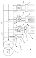
- the fault protection system (1) object of the present invention is a system applicable in abnormal operating situations of the electric power distribution network, such as situations due to maintenance operations, network revamping or incidents in the installations.
- a network area (15) of the high voltage distribution network is insulated from the rest of the network, making up a network area (15) with a ground-insulated neutral point, and therefore, without any protection against the electrical effects caused by ground fault currents.
- electric power generation equipment (2) such as for example a generating set, a microturbine, a fuel cell, etc., is installed in the low voltage side of a first electrical transformation centre (3), this centre (3) being located in the network area (15) which is insulated from the rest of the high voltage network.
- said generation equipment (2) feeds a first low voltage distribution network corresponding to the mentioned first transformation centre (3), as well as the separated network area (15) through at least one transformer (4) housed in said first transformation centre (3), and in short, feeds at least one second affected transformation centre (20) which is in said network area (15).
- This simultaneous feeding of the low voltage network and of the network area (15) is possible due to the incorporation of the fault protection system (1) object of the invention, since said fault protection system (1) provides the necessary protection for the network area (15) against the electrical effects caused by ground fault currents, assuring the safety of both equipment items and of people during these abnormal operating situations.
- the fault protection system (1) is installed between a high voltage side of the first centre (3) and a low voltage side of said centre (3), in a position preceding the electric power generation equipment (2), i.e., between the connection of the electric power generator (2) and the low voltage side of the transformer (4) of the mentioned first centre (3).
- the fault protection system (1) which is a portable system, is configured to detect a ground fault and to issue an order for the electric power generation equipment (2) to stop operating.
- the fault protection system (1) comprises at least one detection device (5) allowing the detection of the line-to-neutral voltage (phase to ground voltage) of at least one phase (11) of the high voltage line of the network area (15), using the actual grounding network of the low voltage side of the first transformation centre (3) as ground reference.
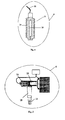
- the detection of the line-to-neutral voltage can be carried out either through a resistive voltage tap (6) or through a capacitive voltage tap (7), the detection device (5) in both cases being able to be installed both inside the transformation centre (3) and outdoors.
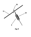
- the resistive voltage tap (6) comprises a precision resistor (14) together with metal inserts embedded in an insulator (19) made of polymeric material, such as for example epoxy resin, silicone, etc., said inserts corresponding with the electrodes between the high voltage active point and the ground of the installation.
- the fault protection system (1) comprises interconnection means (10) which, depending on the location of the detection device (5), can consist of a direct threaded connection (see Figure 6 ), an articulated connection (see Figure 7 ) or an overhead connection (see Figure 8 ).
- resistive voltage tap (6) is installed in the terminals (18) of the power cables of the mentioned phases (11) of the high voltage line, either the terminals of the power cables of the high voltage cells or the terminals of the high voltage power cables of the transformer (4).
- said capacitive voltage tap (7) comprises standardizing shields (12) for standardizing the electric field integrated in at least one bushing (13) in which the high voltage power cable, either of the transformer (4) or of the high voltage distribution cells, is connected. Therefore, in this case the detection device (5) is integrated in the actual bushings (13), either of the transformer (4) or of the cell.
- Figure 3 shows another possible solution of the capacitive voltage tap (7), in which the capacitive voltage tap (7) is installed in the terminals (18) of the high voltage power cables, either the terminals (18) of the power cables of the high voltage cells or the terminals (18) of the high voltage power cables of the transformer (4).
- the fault protection system (1) further comprises at least one control / protection device (8) which obtains and controls the homopolar voltage value from the line-to-neutral voltages detected by the detection device (5).
- this control / protection device (8) will order the electric power generation equipment (2) to halt through the opening of a normally closed contact.
- the fault protection system (1) comprises interconnection means (9) between the detection device (5) and the control / protection device (8).
- the interconnection means (9) consist of a wiring kit allowing the connection of both devices (5) and (8).
- the invention is not limited to the specific embodiments which have been described but rather it also encompasses, for example, the embodiments which can be carried out by a person skilled in the art (for example, with regard to the choice of materials, dimensions, components, configuration, etc.), within what is inferred from the claims.
Landscapes
- Engineering & Computer Science (AREA)
- Power Engineering (AREA)
- Emergency Protection Circuit Devices (AREA)
Priority Applications (2)
| Application Number | Priority Date | Filing Date | Title |
|---|---|---|---|
| EP08380329.6A EP2194628B1 (fr) | 2008-12-02 | 2008-12-02 | Système de protection contre les défauts pour une zone de réseau d'un réseau de distribution haute tension |
| ES08380329.6T ES2666495T3 (es) | 2008-12-02 | 2008-12-02 | Sistema de protección contra fallos para un área de red de una red de distribución de alta tensión |
Applications Claiming Priority (1)
| Application Number | Priority Date | Filing Date | Title |
|---|---|---|---|
| EP08380329.6A EP2194628B1 (fr) | 2008-12-02 | 2008-12-02 | Système de protection contre les défauts pour une zone de réseau d'un réseau de distribution haute tension |
Publications (2)
| Publication Number | Publication Date |
|---|---|
| EP2194628A1 true EP2194628A1 (fr) | 2010-06-09 |
| EP2194628B1 EP2194628B1 (fr) | 2018-01-24 |
Family
ID=40512917
Family Applications (1)
| Application Number | Title | Priority Date | Filing Date |
|---|---|---|---|
| EP08380329.6A Active EP2194628B1 (fr) | 2008-12-02 | 2008-12-02 | Système de protection contre les défauts pour une zone de réseau d'un réseau de distribution haute tension |
Country Status (2)
| Country | Link |
|---|---|
| EP (1) | EP2194628B1 (fr) |
| ES (1) | ES2666495T3 (fr) |
Cited By (5)
| Publication number | Priority date | Publication date | Assignee | Title |
|---|---|---|---|---|
| WO2016050994A1 (fr) * | 2014-10-01 | 2016-04-07 | Ormazabal Protection & Automation, S.L.U. | Adaptateur isolé à haute tension |
| CN106356842A (zh) * | 2016-09-13 | 2017-01-25 | 重庆大学 | 一种低压配电网双电压配电方法 |
| CN109615207A (zh) * | 2018-12-04 | 2019-04-12 | 国网山东省电力公司无棣县供电公司 | 一种低压台区供电负荷调配方法及系统 |
| CN112153857A (zh) * | 2020-06-11 | 2020-12-29 | 安徽正广电电力技术有限公司 | 一种配电网全电压故障在线监测设备 |
| CN113991616A (zh) * | 2021-11-12 | 2022-01-28 | 国网辽宁省电力有限公司检修分公司 | 一种基于双母线接线方式的母线保护设备更换方法 |
Citations (4)
| Publication number | Priority date | Publication date | Assignee | Title |
|---|---|---|---|---|
| US3906477A (en) * | 1974-09-06 | 1975-09-16 | Schweitzer Edmund O Jun | Fault indicator in test point cap |
| EP0015558A1 (fr) * | 1979-03-08 | 1980-09-17 | Karl Pfisterer Elektrotechnische Spezialartikel GmbH & Co. KG | Dispositif détecteur et indicateur associé à un connecteur isolé pour cable électrique |
| JPS63274331A (ja) * | 1987-04-30 | 1988-11-11 | Mitsubishi Electric Corp | コ−ジエネレ−シヨン自動しや断装置 |
| JP2002199578A (ja) * | 2000-12-28 | 2002-07-12 | Toko Electric Corp | 系統連系保護装置 |
-
2008
- 2008-12-02 EP EP08380329.6A patent/EP2194628B1/fr active Active
- 2008-12-02 ES ES08380329.6T patent/ES2666495T3/es active Active
Patent Citations (4)
| Publication number | Priority date | Publication date | Assignee | Title |
|---|---|---|---|---|
| US3906477A (en) * | 1974-09-06 | 1975-09-16 | Schweitzer Edmund O Jun | Fault indicator in test point cap |
| EP0015558A1 (fr) * | 1979-03-08 | 1980-09-17 | Karl Pfisterer Elektrotechnische Spezialartikel GmbH & Co. KG | Dispositif détecteur et indicateur associé à un connecteur isolé pour cable électrique |
| JPS63274331A (ja) * | 1987-04-30 | 1988-11-11 | Mitsubishi Electric Corp | コ−ジエネレ−シヨン自動しや断装置 |
| JP2002199578A (ja) * | 2000-12-28 | 2002-07-12 | Toko Electric Corp | 系統連系保護装置 |
Cited By (10)
| Publication number | Priority date | Publication date | Assignee | Title |
|---|---|---|---|---|
| WO2016050994A1 (fr) * | 2014-10-01 | 2016-04-07 | Ormazabal Protection & Automation, S.L.U. | Adaptateur isolé à haute tension |
| AU2014407928B2 (en) * | 2014-10-01 | 2018-04-05 | Ormazabal Protection and Automation, S.L.U. | Insulated high-voltage adapter |
| US10348046B2 (en) | 2014-10-01 | 2019-07-09 | Ormazabal Protection & Automation, S.L.U. | Insulated high-voltage adapter |
| CN106356842A (zh) * | 2016-09-13 | 2017-01-25 | 重庆大学 | 一种低压配电网双电压配电方法 |
| CN106356842B (zh) * | 2016-09-13 | 2018-12-04 | 重庆大学 | 一种低压配电网双电压配电方法 |
| CN109615207A (zh) * | 2018-12-04 | 2019-04-12 | 国网山东省电力公司无棣县供电公司 | 一种低压台区供电负荷调配方法及系统 |
| CN112153857A (zh) * | 2020-06-11 | 2020-12-29 | 安徽正广电电力技术有限公司 | 一种配电网全电压故障在线监测设备 |
| CN112153857B (zh) * | 2020-06-11 | 2023-07-14 | 安徽正广电电力技术有限公司 | 一种配电网全电压故障在线监测设备 |
| CN113991616A (zh) * | 2021-11-12 | 2022-01-28 | 国网辽宁省电力有限公司检修分公司 | 一种基于双母线接线方式的母线保护设备更换方法 |
| CN113991616B (zh) * | 2021-11-12 | 2023-05-30 | 国网辽宁省电力有限公司检修分公司 | 一种基于双母线接线方式的母线保护设备更换方法 |
Also Published As
| Publication number | Publication date |
|---|---|
| EP2194628B1 (fr) | 2018-01-24 |
| ES2666495T3 (es) | 2018-05-04 |
Similar Documents
| Publication | Publication Date | Title |
|---|---|---|
| CN101682188B (zh) | 用于对位于远处的负载进行电力传输的电力站 | |
| WO2020193942A1 (fr) | Système d'arrêt et de détection de pen ouvert | |
| EP2194628B1 (fr) | Système de protection contre les défauts pour une zone de réseau d'un réseau de distribution haute tension | |
| US6023400A (en) | Safety adapter for ungrounded electrical socket | |
| US20260008373A1 (en) | Voltage-based disconnection of electrical vehicle supply equipment | |
| EP1278282A1 (fr) | Procédé et dispositif pour isoler d'une première section d'un réseau électrique d'une deuxième section | |
| Paul et al. | Low-voltage shore connection power systems: Optional designs and a safety loop circuit | |
| WO2009124338A1 (fr) | Dispositif de protection électrique et système de distribution électrique incluant un dispositif de protection électrique | |
| Jullien et al. | The IT earthing system (unearthed neutral) in LV | |
| Paul et al. | Cold ironing-power system grounding and safety analysis | |
| GB2606005A (en) | Detecting an open pen conductor | |
| Topolánek et al. | Practical experience of using additional earthing of the faulty phase during a ground fault | |
| Sen et al. | Design of 132/33KV Substation | |
| Gudzius et al. | Characteristics of fault detection system for smart grid distribution network | |
| West | Grounding for emergency and standby power systems | |
| RU2788519C1 (ru) | Способ отключения поврежденного присоединения с однофазным замыканием на землю в сетях с изолированной нейтралью | |
| EP4339988A1 (fr) | Dispositif passif de protection contre les défauts pour un transformateur de tension de mesure ou un transformateur de tension de puissance pour utilisation dans des applications haute tension | |
| Cohen | Loss of neutral in low voltage distribution systems-consequences and solutions | |
| Paul et al. | Low-voltage shore connection power systems | |
| RU2442258C2 (ru) | Электростанция для передачи энергии к удаленно расположенной нагрузке | |
| Shirkovets et al. | Schemes, Neutral Grounding Treatment and Organization of Ground Fault Relay Protection in 20 kV Networks of Megalopolises | |
| KR100654773B1 (ko) | 가스절연형 파워퓨즈를 구비한 수변전장치 | |
| Chandra | Practices and Regulations Followed for Earthing of lt Distribution and Consumer Premises | |
| Kries et al. | Application of a Permanent Voltage Detection and Indication System (VDIS) for Reliable Personnel Safety and Monitoring of the Presence of Power in Switchgear Equipment; Experiences from the IEC Market for the US | |
| Ashok | 400KV SUBSTATION AREECODE POWER GRID CORPORATION OF INDIA |
Legal Events
| Date | Code | Title | Description |
|---|---|---|---|
| PUAI | Public reference made under article 153(3) epc to a published international application that has entered the european phase |
Free format text: ORIGINAL CODE: 0009012 |
|
| AK | Designated contracting states |
Kind code of ref document: A1 Designated state(s): AT BE BG CH CY CZ DE DK EE ES FI FR GB GR HR HU IE IS IT LI LT LU LV MC MT NL NO PL PT RO SE SI SK TR |
|
| AX | Request for extension of the european patent |
Extension state: AL BA MK RS |
|
| 17P | Request for examination filed |
Effective date: 20101201 |
|
| AKX | Designation fees paid |
Designated state(s): AT BE BG CH CY CZ DE DK EE ES FI FR GB GR HR HU IE IS IT LI LT LU LV MC MT NL NO PL PT RO SE SI SK TR |
|
| TPAC | Observations filed by third parties |
Free format text: ORIGINAL CODE: EPIDOSNTIPA |
|
| GRAP | Despatch of communication of intention to grant a patent |
Free format text: ORIGINAL CODE: EPIDOSNIGR1 |
|
| STAA | Information on the status of an ep patent application or granted ep patent |
Free format text: STATUS: GRANT OF PATENT IS INTENDED |
|
| GRAS | Grant fee paid |
Free format text: ORIGINAL CODE: EPIDOSNIGR3 |
|
| INTG | Intention to grant announced |
Effective date: 20171006 |
|
| GRAA | (expected) grant |
Free format text: ORIGINAL CODE: 0009210 |
|
| STAA | Information on the status of an ep patent application or granted ep patent |
Free format text: STATUS: THE PATENT HAS BEEN GRANTED |
|
| AK | Designated contracting states |
Kind code of ref document: B1 Designated state(s): AT BE BG CH CY CZ DE DK EE ES FI FR GB GR HR HU IE IS IT LI LT LU LV MC MT NL NO PL PT RO SE SI SK TR |
|
| REG | Reference to a national code |
Ref country code: GB Ref legal event code: FG4D |
|
| REG | Reference to a national code |
Ref country code: CH Ref legal event code: EP |
|
| REG | Reference to a national code |
Ref country code: AT Ref legal event code: REF Ref document number: 966283 Country of ref document: AT Kind code of ref document: T Effective date: 20180215 |
|
| REG | Reference to a national code |
Ref country code: IE Ref legal event code: FG4D |
|
| REG | Reference to a national code |
Ref country code: DE Ref legal event code: R096 Ref document number: 602008053844 Country of ref document: DE |
|
| REG | Reference to a national code |
Ref country code: ES Ref legal event code: FG2A Ref document number: 2666495 Country of ref document: ES Kind code of ref document: T3 Effective date: 20180504 |
|
| REG | Reference to a national code |
Ref country code: NL Ref legal event code: MP Effective date: 20180124 |
|
| REG | Reference to a national code |
Ref country code: LT Ref legal event code: MG4D |
|
| REG | Reference to a national code |
Ref country code: AT Ref legal event code: MK05 Ref document number: 966283 Country of ref document: AT Kind code of ref document: T Effective date: 20180124 |
|
| PG25 | Lapsed in a contracting state [announced via postgrant information from national office to epo] |
Ref country code: NL Free format text: LAPSE BECAUSE OF FAILURE TO SUBMIT A TRANSLATION OF THE DESCRIPTION OR TO PAY THE FEE WITHIN THE PRESCRIBED TIME-LIMIT Effective date: 20180124 |
|
| PG25 | Lapsed in a contracting state [announced via postgrant information from national office to epo] |
Ref country code: LT Free format text: LAPSE BECAUSE OF FAILURE TO SUBMIT A TRANSLATION OF THE DESCRIPTION OR TO PAY THE FEE WITHIN THE PRESCRIBED TIME-LIMIT Effective date: 20180124 Ref country code: CY Free format text: LAPSE BECAUSE OF FAILURE TO SUBMIT A TRANSLATION OF THE DESCRIPTION OR TO PAY THE FEE WITHIN THE PRESCRIBED TIME-LIMIT Effective date: 20180124 Ref country code: HR Free format text: LAPSE BECAUSE OF FAILURE TO SUBMIT A TRANSLATION OF THE DESCRIPTION OR TO PAY THE FEE WITHIN THE PRESCRIBED TIME-LIMIT Effective date: 20180124 Ref country code: NO Free format text: LAPSE BECAUSE OF FAILURE TO SUBMIT A TRANSLATION OF THE DESCRIPTION OR TO PAY THE FEE WITHIN THE PRESCRIBED TIME-LIMIT Effective date: 20180424 Ref country code: FI Free format text: LAPSE BECAUSE OF FAILURE TO SUBMIT A TRANSLATION OF THE DESCRIPTION OR TO PAY THE FEE WITHIN THE PRESCRIBED TIME-LIMIT Effective date: 20180124 |
|
| PG25 | Lapsed in a contracting state [announced via postgrant information from national office to epo] |
Ref country code: BG Free format text: LAPSE BECAUSE OF FAILURE TO SUBMIT A TRANSLATION OF THE DESCRIPTION OR TO PAY THE FEE WITHIN THE PRESCRIBED TIME-LIMIT Effective date: 20180424 Ref country code: GR Free format text: LAPSE BECAUSE OF FAILURE TO SUBMIT A TRANSLATION OF THE DESCRIPTION OR TO PAY THE FEE WITHIN THE PRESCRIBED TIME-LIMIT Effective date: 20180425 Ref country code: PL Free format text: LAPSE BECAUSE OF FAILURE TO SUBMIT A TRANSLATION OF THE DESCRIPTION OR TO PAY THE FEE WITHIN THE PRESCRIBED TIME-LIMIT Effective date: 20180124 Ref country code: LV Free format text: LAPSE BECAUSE OF FAILURE TO SUBMIT A TRANSLATION OF THE DESCRIPTION OR TO PAY THE FEE WITHIN THE PRESCRIBED TIME-LIMIT Effective date: 20180124 Ref country code: AT Free format text: LAPSE BECAUSE OF FAILURE TO SUBMIT A TRANSLATION OF THE DESCRIPTION OR TO PAY THE FEE WITHIN THE PRESCRIBED TIME-LIMIT Effective date: 20180124 Ref country code: IS Free format text: LAPSE BECAUSE OF FAILURE TO SUBMIT A TRANSLATION OF THE DESCRIPTION OR TO PAY THE FEE WITHIN THE PRESCRIBED TIME-LIMIT Effective date: 20180524 Ref country code: SE Free format text: LAPSE BECAUSE OF FAILURE TO SUBMIT A TRANSLATION OF THE DESCRIPTION OR TO PAY THE FEE WITHIN THE PRESCRIBED TIME-LIMIT Effective date: 20180124 |
|
| REG | Reference to a national code |
Ref country code: DE Ref legal event code: R097 Ref document number: 602008053844 Country of ref document: DE |
|
| PG25 | Lapsed in a contracting state [announced via postgrant information from national office to epo] |
Ref country code: RO Free format text: LAPSE BECAUSE OF FAILURE TO SUBMIT A TRANSLATION OF THE DESCRIPTION OR TO PAY THE FEE WITHIN THE PRESCRIBED TIME-LIMIT Effective date: 20180124 Ref country code: IT Free format text: LAPSE BECAUSE OF FAILURE TO SUBMIT A TRANSLATION OF THE DESCRIPTION OR TO PAY THE FEE WITHIN THE PRESCRIBED TIME-LIMIT Effective date: 20180124 Ref country code: EE Free format text: LAPSE BECAUSE OF FAILURE TO SUBMIT A TRANSLATION OF THE DESCRIPTION OR TO PAY THE FEE WITHIN THE PRESCRIBED TIME-LIMIT Effective date: 20180124 |
|
| PG25 | Lapsed in a contracting state [announced via postgrant information from national office to epo] |
Ref country code: CZ Free format text: LAPSE BECAUSE OF FAILURE TO SUBMIT A TRANSLATION OF THE DESCRIPTION OR TO PAY THE FEE WITHIN THE PRESCRIBED TIME-LIMIT Effective date: 20180124 Ref country code: DK Free format text: LAPSE BECAUSE OF FAILURE TO SUBMIT A TRANSLATION OF THE DESCRIPTION OR TO PAY THE FEE WITHIN THE PRESCRIBED TIME-LIMIT Effective date: 20180124 Ref country code: SK Free format text: LAPSE BECAUSE OF FAILURE TO SUBMIT A TRANSLATION OF THE DESCRIPTION OR TO PAY THE FEE WITHIN THE PRESCRIBED TIME-LIMIT Effective date: 20180124 |
|
| PLBE | No opposition filed within time limit |
Free format text: ORIGINAL CODE: 0009261 |
|
| STAA | Information on the status of an ep patent application or granted ep patent |
Free format text: STATUS: NO OPPOSITION FILED WITHIN TIME LIMIT |
|
| 26N | No opposition filed |
Effective date: 20181025 |
|
| PG25 | Lapsed in a contracting state [announced via postgrant information from national office to epo] |
Ref country code: SI Free format text: LAPSE BECAUSE OF FAILURE TO SUBMIT A TRANSLATION OF THE DESCRIPTION OR TO PAY THE FEE WITHIN THE PRESCRIBED TIME-LIMIT Effective date: 20180124 |
|
| REG | Reference to a national code |
Ref country code: CH Ref legal event code: PL |
|
| GBPC | Gb: european patent ceased through non-payment of renewal fee |
Effective date: 20181202 |
|
| PG25 | Lapsed in a contracting state [announced via postgrant information from national office to epo] |
Ref country code: MC Free format text: LAPSE BECAUSE OF FAILURE TO SUBMIT A TRANSLATION OF THE DESCRIPTION OR TO PAY THE FEE WITHIN THE PRESCRIBED TIME-LIMIT Effective date: 20180124 Ref country code: LU Free format text: LAPSE BECAUSE OF NON-PAYMENT OF DUE FEES Effective date: 20181202 |
|
| REG | Reference to a national code |
Ref country code: IE Ref legal event code: MM4A |
|
| REG | Reference to a national code |
Ref country code: BE Ref legal event code: MM Effective date: 20181231 |
|
| PG25 | Lapsed in a contracting state [announced via postgrant information from national office to epo] |
Ref country code: IE Free format text: LAPSE BECAUSE OF NON-PAYMENT OF DUE FEES Effective date: 20181202 |
|
| PG25 | Lapsed in a contracting state [announced via postgrant information from national office to epo] |
Ref country code: BE Free format text: LAPSE BECAUSE OF NON-PAYMENT OF DUE FEES Effective date: 20181231 |
|
| PG25 | Lapsed in a contracting state [announced via postgrant information from national office to epo] |
Ref country code: GB Free format text: LAPSE BECAUSE OF NON-PAYMENT OF DUE FEES Effective date: 20181202 Ref country code: CH Free format text: LAPSE BECAUSE OF NON-PAYMENT OF DUE FEES Effective date: 20181231 Ref country code: LI Free format text: LAPSE BECAUSE OF NON-PAYMENT OF DUE FEES Effective date: 20181231 |
|
| PG25 | Lapsed in a contracting state [announced via postgrant information from national office to epo] |
Ref country code: MT Free format text: LAPSE BECAUSE OF NON-PAYMENT OF DUE FEES Effective date: 20181202 |
|
| PG25 | Lapsed in a contracting state [announced via postgrant information from national office to epo] |
Ref country code: TR Free format text: LAPSE BECAUSE OF FAILURE TO SUBMIT A TRANSLATION OF THE DESCRIPTION OR TO PAY THE FEE WITHIN THE PRESCRIBED TIME-LIMIT Effective date: 20180124 |
|
| PG25 | Lapsed in a contracting state [announced via postgrant information from national office to epo] |
Ref country code: PT Free format text: LAPSE BECAUSE OF FAILURE TO SUBMIT A TRANSLATION OF THE DESCRIPTION OR TO PAY THE FEE WITHIN THE PRESCRIBED TIME-LIMIT Effective date: 20180124 |
|
| PG25 | Lapsed in a contracting state [announced via postgrant information from national office to epo] |
Ref country code: HU Free format text: LAPSE BECAUSE OF FAILURE TO SUBMIT A TRANSLATION OF THE DESCRIPTION OR TO PAY THE FEE WITHIN THE PRESCRIBED TIME-LIMIT; INVALID AB INITIO Effective date: 20081202 |
|
| PGFP | Annual fee paid to national office [announced via postgrant information from national office to epo] |
Ref country code: DE Payment date: 20211209 Year of fee payment: 14 |
|
| REG | Reference to a national code |
Ref country code: DE Ref legal event code: R119 Ref document number: 602008053844 Country of ref document: DE |
|
| PG25 | Lapsed in a contracting state [announced via postgrant information from national office to epo] |
Ref country code: DE Free format text: LAPSE BECAUSE OF NON-PAYMENT OF DUE FEES Effective date: 20230701 |
|
| PGFP | Annual fee paid to national office [announced via postgrant information from national office to epo] |
Ref country code: ES Payment date: 20240105 Year of fee payment: 16 |
|
| PGFP | Annual fee paid to national office [announced via postgrant information from national office to epo] |
Ref country code: FR Payment date: 20251205 Year of fee payment: 18 |
|
| REG | Reference to a national code |
Ref country code: ES Ref legal event code: FD2A Effective date: 20260126 |
|
| PG25 | Lapsed in a contracting state [announced via postgrant information from national office to epo] |
Ref country code: ES Free format text: LAPSE BECAUSE OF NON-PAYMENT OF DUE FEES Effective date: 20241203 |