EP2194881B1 - Externe fixationsanordnung - Google Patents
Externe fixationsanordnung Download PDFInfo
- Publication number
- EP2194881B1 EP2194881B1 EP08833815.7A EP08833815A EP2194881B1 EP 2194881 B1 EP2194881 B1 EP 2194881B1 EP 08833815 A EP08833815 A EP 08833815A EP 2194881 B1 EP2194881 B1 EP 2194881B1
- Authority
- EP
- European Patent Office
- Prior art keywords
- contoured
- segment
- segments
- disposed
- length
- Prior art date
- Legal status (The legal status is an assumption and is not a legal conclusion. Google has not performed a legal analysis and makes no representation as to the accuracy of the status listed.)
- Active
Links
Images




Classifications
-
- A—HUMAN NECESSITIES
- A61—MEDICAL OR VETERINARY SCIENCE; HYGIENE
- A61B—DIAGNOSIS; SURGERY; IDENTIFICATION
- A61B17/00—Surgical instruments, devices or methods
- A61B17/56—Surgical instruments or methods for treatment of bones or joints; Devices specially adapted therefor
- A61B17/58—Surgical instruments or methods for treatment of bones or joints; Devices specially adapted therefor for osteosynthesis, e.g. bone plates, screws or setting implements
- A61B17/60—Surgical instruments or methods for treatment of bones or joints; Devices specially adapted therefor for osteosynthesis, e.g. bone plates, screws or setting implements for external osteosynthesis, e.g. distractors, contractors
- A61B17/64—Devices extending alongside the bones to be positioned
- A61B17/6425—Devices extending alongside the bones to be positioned specially adapted to be fitted across a bone joint
-
- A—HUMAN NECESSITIES
- A61—MEDICAL OR VETERINARY SCIENCE; HYGIENE
- A61B—DIAGNOSIS; SURGERY; IDENTIFICATION
- A61B17/00—Surgical instruments, devices or methods
- A61B17/56—Surgical instruments or methods for treatment of bones or joints; Devices specially adapted therefor
- A61B17/58—Surgical instruments or methods for treatment of bones or joints; Devices specially adapted therefor for osteosynthesis, e.g. bone plates, screws or setting implements
- A61B17/60—Surgical instruments or methods for treatment of bones or joints; Devices specially adapted therefor for osteosynthesis, e.g. bone plates, screws or setting implements for external osteosynthesis, e.g. distractors, contractors
- A61B17/64—Devices extending alongside the bones to be positioned
- A61B17/6441—Bilateral fixators, i.e. with both ends of pins or wires clamped
Definitions
- a support assembly comprises a base segment configured to at least partially surround the ankle area and one or more contoured segments each including a contoured portion.
- the contoured portion extends transversely outward from its contoured segment, along a length or height of the ankle or talus area and is structured to dispose one or more transfixion pins at any of a plurality of preferred orientations to engage and efficiently stabilize predetermined portions of the ankle area.
- fixator assemblies are commonly used to maintain segments of the bone in an intended and/or required stabilized orientation.
- fixator assemblies of the type described may be utilized to treat the fusion of bone tissue as well soft tissue injuries, and situations involving a union of bones which otherwise are difficult to heal.
- known or conventional fixator assemblies vary in structure, dimension and configuration and are correspondingly adapted to be used with various portions of the body to which they are attached.
- Typical fixator structures include one or more connecting bars or rods as well a plurality of clamps for adjustably securing fixation pins, wires, etc. to the bone portions being affected.
- transfixion pins or wires of the types commonly utilized may extend completely through the bony tissue or may be anchored therein, such as when the long bones of the leg are involved directly or indirectly with the treatment or healing procedure.
- the term "transfixion member” is generally recognized in the medical field as including the describing of elongated pins which extend completely or at least partially through the bony tissue involved.
- smaller, thicker "half pins" may be utilized in substantially the same manner to stabilize affected tissue but being of a length insufficient to extend completely through the affected bone, joint, etc. This term may also be used in a more generic sense in referring to stabilizing devices, other than pins, such as wires, reduction wires, screws, clamps, etc.
- known external fixator assemblies of the type described may also include support rings which encircle a corresponding body member, wherein such rings or like support members serve as a supportive base to facilitate proper location of the aforementioned transfixion members. Accordingly, it is commonly understood in the medical profession that fixator assemblies are used to maintain proper orientation of one or more of bones or bone segments relative to one another to facilitate healing or alignment.
- the proper stabilization of tissue typically associated with the joint areas of a patient's body such as, but not limited to, the ankle joint as well as the wrist and other smaller bones associated with the hand involves additional considerations.
- the fixator clamps or fixation clamps support blocks are frequently connected to an encircling halo-ring or like support member.
- These devices are mounted on the ring or other support member to properly position a transfixion pin or like member at a proper height or corresponding distance above the supporting ring in order to engage and thereby properly orient the affected bones of the ankle joint to the foot.
- US 5,496,319 A discloses an external fixation apparatus that allows a transfixation wire to be secured at a plurality of discrete positions to provide adjustability of the angular orientation of the wire with respect to the plane of a frame ring.
- the fixation apparatus includes a transfixation wire or pin that is connected between a transmitting clamp and a receiving clamp that are shiftably carried atop of a partial frame ring.
- a wire retainer is secured to the distal end of the transfixation wire.
- the receiving clamp includes a raised member adapted for receiving the distal end of the wire and mating with the retainer at a variety of discrete positions along the length of the raised member.
- the retainer uses two screws to secure the distal end of the wire within a longitudinal through bore. A screw extends into the longitudinal bore to engage the wire near the proximal end of the retainer. Another screw extends into the longitudinal bore and bends the distal end of the wire downward within a slot defined along the longitudinal bore at the distal end of the retainer.
- WO 2007/067297 A2 discloses an external fixation system for a bone.
- the fixation system includes a proximal frame defining a continuous proximal boundary, a distal frame defining a continuous distal boundary, and at least one frame connector configured for interconnecting the proximal and distal frames at any position along at least one of the proximal and distal boundaries.
- the fracture reduction assembly may include a reduction platform, and a threaded fragment manipulator.
- the reduction platform has top and bottom surfaces and at least one receiving hole in communication therewith.
- the receiving hole is configured to accept a fragment manipulator.
- the fragment manipulator may comprise an elongated member having a bone engaging portion for engaging a targeted fractured bone piece and a center threaded portion.
- the fragment manipulator provides accurate control over the fragment reduction vector.
- the bone engaging end of the fragment manipulator is inserted through the receiving hole in the reduction platform and then into the fracture region where it engages the targeted fractured bone piece.
- an adjustable support assembly which may be used to position the reduction platform in a wide variety of locations above the fracture region.
- an external fixator assembly which more efficiently stabilizes or otherwise serves to operatively orient the components and tissue associated with the foot and ankle areas and/or the associated bones of the lower leg corresponding to a connection with the ankle area joint and the foot.
- fixator assembly is provided as set forth in claim 1.
- Preferred embodiments of the present invention may be gathered from the dependent claims.
- This invention is directed to an external fixator assembly primarily, but not exclusively, structured for placement adjacent an ankle area of the body.
- the term "ankle area” is intended to describe the ankle joint, as well as bones and associated tissue of the foot and lower portions of the leg bones including the fibula and tibia.
- terminology including "length of the ankle area” and/or “height of the ankle area” may be utilized synonymously. These terms are meant to refer to the general distance between the bottom of the foot and an area of the lower part of the leg above the ankle joint.
- the external fixator assembly of the present invention comprises a support assembly intended to be disposed adjacent the ankle area and structured to support at least one transfixion pin or like transfixion member in operative engagement with the bones or other associated tissue associated with the ankle area.
- the support assembly includes at least one base segment preferably, but not necessarily having a curvilinear configuration substantially in the form of an arc and/or semicircle operatively disposed at the medial and lateral longitudinal segments.
- the support assembly includes at least one, and in some applications at least two elongated contoured segments connected to the base segment, which could also be accurately described and/or referred to as a contoured anatomical foot plate.
- Each of the one or more contoured segments includes a contoured portion, dimensioned and configured to medically imitate the arch of the foot.
- the contoured portion is disposed along the length of the corresponding contoured segment and extends transversely outward from a remainder of the length of the contoured segment. Accordingly, when properly positioned adjacent the ankle area, the contoured portion extends transversely outward from its contoured segment and adjacent to and along the length or height of the ankle area.
- each contoured portion includes what may be generally referred to as an angular configuration, which in turn may be more specifically defined by a substantially convergent configuration. Accordingly, the angular or convergent configuration of each contoured portion includes an apex or the like structure representing the maximum outward extension of the contoured portion from a remainder of the length of the corresponding contoured segment.
- each contoured portion is preferably disposed in spaced relation to at least one end of the corresponding contoured segment. In at least one preferred embodiment the contoured portion is intermediately disposed between the opposite ends of the contoured segment. Interconnection of each contoured segment to the base segment of the support assembly is defined by a fixed, integral or removable attachment of one of the opposite ends of the contoured segment to a corresponding end or other appropriate portion of the base segment. As set forth above, the same base segment of the support assembly may be utilized to support and properly position at least two contoured segments. When this embodiment of the fixator assembly is utilized, opposite ends of the base segment are fixedly, integrally or removably secured to a corresponding end of each of the elongated contoured segments.
- each of the two contoured segments are operatively positioned on substantially opposite sides of the ankle area and in spaced but adjacent relation thereto.
- corresponding ones of the contoured portions of each contoured segment extends transversely outward from the length of the corresponding contoured segment and along the height or length of the ankle area.
- Another feature of the various preferred embodiments of the fixator assembly of the present invention, whether utilizing one or more contoured segments, is the ability to connect one or more transfixion pins or like transfixion members to the one or more contoured segments.
- the transfixion pin(s) or member (s) When connected to the contoured segment (s) in the intended manner, the transfixion pin(s) or member (s) extends transversely inward, towards the affected portions of the ankle area, from the contoured segment to which it is attached into stabilizing engagement with the bone or other tissue associated with the ankle area at various points along the height or length of the ankle area.
- each of the one or more transfixion pins can be connected to a contoured segment at a plurality of different locations along the length thereof including, but not limited to, a plurality of locations along the length of the contoured portion of the corresponding contoured segment.
- the angular and/or convergent configuration of the contoured portion provides significant versatility in positioning each of the one or more transfixion pins or members at any one of a plurality of different locations each representing an orientation having a different height or length relative to the ankle area.
- the positioning of the transfixion pin(s) or member(s) into stabilizing engagement with intended tissue of the ankle area eliminates or significantly reduces the need for conventional support blocks or clamps to connect the transfixion pin(s).
- the use of such known devices and procedures for orienting of the transfixion pins relative to a predetermined body part is time consuming and has a tendency to obscure X-rays or other viewing facilities of the body part. Therefore the use of the various preferred embodiments of the present invention eliminate or significantly reduce such known and well recognized disadvantages.
- the present invention is directed to an external fixator assembly generally indicated as 10.
- the fixator assembly 10 is structured to be operatively positioned and used in a location substantially adjacent to the ankle area 12 of a patient, as best represented in Figure 1 .
- the ankle area 12 is meant to be descriptive of substantially the entire area represented in Figure 1 , which includes the ankle joint, foot, corresponding portions of the leg bones, including the fibula and tibia, as well as the associated components and tissue.
- the terms "height" and “length” of the ankle area 12 are used synonymously herein and refer to the distance from substantially the bottom of the foot, as at 14, to at least a portion the long bones of the leg, as at 16.
- the external fixator assembly 10 comprises a support assembly generally indicated as 18 and including a base segment 20 and at least one contoured segment generally indicated as 22.
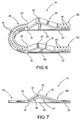
- the support assembly 18 may include more than one contoured segment 22 as schematically represented in Figure 7 , wherein two contoured segments 22 and 22' are operatively positioned relative to the ankle area 12.
- the one or more contoured segments utilized may be selected from a larger plurality of contoured segments 22, 22', etc., which may differ from one another at least in dimension and configuration, as will be explained in greater detail hereinafter.
- the base segment 20, defining at least a portion of the support assembly 18, preferably includes a curvilinear configuration which may be more specifically defined by an arcuate or semicircular shape.
- the base segment 20 terminates in oppositely disposed free ends 23 and 23'.
- a plurality of apertures or other appropriate structure 25 are positioned substantially along the length of the base segment 20 and are provided to facilitate connection of one or more struts to the base segment 20 preferably using fixation bolts, which are not shown for purposes of clarity.
- fixation bolts Such struts and interconnecting fixation bolts are well-known in the medical profession and are used to support and/or dispose the base segment 20 in a stabilized position relative to the ankle area 12.
- struts to which the base segment 20 is connected, may be secured to a halo-type ring located above the ankle area 12 along the length of the leg and in surrounding relation to the bones 16' of the leg 16.
- the halo-type support ring is also well-known in the medical profession and is structured to have a plurality of transfixion pins secured thereto so as to extend radially inward into a firm connection with the bone(s) 16' of the leg 16.
- Such anchoring of the halo ring provides stabilizing support to the base segment 20 by virtue of the interconnection between the halo ring and the base segment 20 by the plurality of strut members, as is well-known.
- the base segment 20 is disposed in at least partially surrounding but spaced relation to a portion of the ankle area 12, such as in the vicinity of the heel 12'.
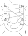
- the plurality of apertures or like connecting facilities 25 are not pictured in Figure 5 but are intended to be present therein during the actual practical application or use of the fixator assembly 10.
- operative placement and use of the fixator assembly 10 comprises the supported disposition of at least one contoured segment 22 or 22' adjacent to an appropriate side of the ankle area 12. More specifically, contoured segment 22', having the smaller or lesser protruding contoured portion 30 is normally placed adjacent the lateral side of the foot and/or ankle area 12. In cooperation therewith, the contoured segment 22, having the larger or greater outwardly protruding portion 30 is normally, but not exclusively, appropriately positioned adjacent the medial side of the foot and/or ankle area 12.
- operative disposition and use of the fixator assembly 10 may comprise utilization of two of the contoured segments 22 and 22', wherein each is connected to correspondingly disposed ends 23 and 23' of the base segment 20. It is noted that the interconnection of the one or more contoured segments 22 and 22' to the base segment 20 may be removably connected, in a stable manner, through the use of appropriate connectors as at 29. Alternatively, one or both of the contoured segments 22 and 22' may be integrally or otherwise fixedly and therefore not removably secured to the base segment 20 in a manner which does not facilitate their disconnection from the base segment 20.
- each of a plurality of contoured segments 22, 22', 22" , 22"', etc. is represented, wherein it is emphasized that common structural features do exist between each of a plurality of contoured segments 22, 22', etc.
- each of a possible larger number of contoured segments 22, 22', etc. may vary in dimension and configuration to accommodate accurate placement of a plurality of transfixion wires or members 36 relative to different ankle area 12 of different patients.
- a large number of contoured segments may be made available to the involved medical personnel. This allows the appropriately dimensioned and configured contoured segment(s) to be selected and operatively utilized in different applications.
- the one or more contoured segments 22, 22', etc. are dimensioned and configured to properly position the required transfixion wires, pins or members 36 based, at least in part, on the needs of specific patient.
- the larger number of contoured segments which may be provided also allows the medical personnel to quickly and easily choose an appropriately dimensioned and configured contoured segment to be used on an ankle area 12 of a patient dependent on the size and shape of that portion of a patient's body as well as a particular bones or other tissue which must be stabilized or otherwise treated.
- each of the contoured segments 22, 22', etc. includes a contoured portion generally indicated as 30 disposed in spaced relation to at least one end 32 thereof, but more practically in spaced relation to opposite ends 32 and 32' thereof.
- the contoured segment 30, in at least one example of the fixator assembly 10 is disposed intermediate the opposite ends 32 and 32'.
- one of these opposite ends, such as at 32 is fixedly or removably connected to a correspondingly disposed end 23 of the base segment 20.
- each of the contoured segments 22, 22', etc. comprise the contoured portion 30 having a substantially angular configuration as it protrudes transversely outward from a remainder of the length of the corresponding contoured segment 22, 22', etc.
- each of the contoured segments 30 may be more specifically defined by a substantially convergent configuration as each of the contoured portions 30 extend transversely outward from a remainder of the corresponding contoured segment 22 and 22'.
- each of the contoured portions 30 terminates at what may be generally referred to as an apex or upper portion of the contoured segment 30, as at 32. Therefore, when one or more of the contoured segments 22, 22', etc. are operatively positioned as represented in Figures 1 and 7 , a contoured portion 30 of each of the one or more contoured segments 22, 22', etc.
- each of the contoured segments 22, 22', etc. are structured to be connected to and support one or more of a plurality of transfixion members or transfixion wires 36, as represented in Figures 1 and 5 .
- each of the one or more transfixion wires or pins 36 extend transversely inward, toward the appropriate portion of the ankle area 12, from any one of a plurality of possible locations on the contoured segment 22, 22', etc. including, but not limited to, being connected to the contoured portion 30 or other portions of the length of the corresponding contoured segment.
- the plurality of transfixion wires, pins or like members 36 may be located at different heights such that they will extend transversely inward into engaging relation with intended bone tissue or other tissue components of the ankle 12, as represented in both Figures 1 and 5 .
- This versatile placement of the transfixion members 36 allows for the accurate and efficient stabilizing engagement of the transfixion members 36 with the bones or other components of the ankle area 12. More specifically, each of the transfixion members 36 may be located at different orientations along the height or length of the ankle area 12 so as to securely engage or stabilize different tissue portions of the ankle area 12 as required for healing and/or stabilization.
- any of a larger plurality of contoured segments 22, 22', etc. may be available to medical personnel to facilitate the application to ankle areas 12 of different sizes and/or where different bones or like tissue must be engaged by the transfixion members 36.
- the differing size and/or configuration of the plurality of contoured segments 22, 22', etc. is clearly represented in Figures 3 and 4 .
- the contoured portions 30 of the different contoured segments 22 and 22' have the aforementioned angular configuration which may be more specifically defined by a substantially convergent configuration.
- the contoured portions may differ in height and or placement along the length of the corresponding contoured segment.
- the transversely outward location of the apex 33 may differ in the plurality of contoured segments collectively represented as 22 and 22' in Figures 3 and
- the contoured portions 30 of each of the contoured segments 22 and 22' will be located adjacent and in operative relation to an at least minimally different portion of the various bones or other tissue of the ankle area 12. This in turn will facilitate and enhance the versatility of accurately and efficiently placing one or more transfixion wires, pins or like members 36 into engaging, stabilizing relation to the intended bones or other tissue of the ankle area 12. More specifically, as each of the contoured portions 30 of each contoured segment 22, 22', etc.
- transfixion members 36 extend transversely outward from the remainder of the length of the corresponding contoured segments 22, 22', etc., the transversely inward ability to position one or more of the transfixion members 36 into engaging relation with appropriate tissue of the ankle area 12 as represented by a comparison of the Figures 1 and 5 .
- contoured segments 22 and 22' may be typically accomplished by placement of each contoured segment 22 and/or 22' on appropriate and/or lateral and medial sides respectively of the ankle area 12.
- corresponding ends 32, 23 and 32, 23' of the contoured segments 22, 22' and base segment 20 respectively are fixedly or removably connected to one another.
- a variance in the dimension and configuration of the base segment 20 may serve to alter the position of each or both of the contoured segments 22 and 22' relative to the ankle area 12 and/or to one another, from that represented in Figure 5 .
- a fixed or integral connection between the base segment 20 and one or more of the contoured segments 22 and 22' allows the medical personnel to choose an appropriate size and configuration of the support assembly 18 defined by the base segment 20 and one or more of the non-detachable contoured segments 22 and 22'.
- a supply the fixator assemblies 10 may be made available to medical personnel in predetermined and different sizes and configurations. This would alleviate the necessity of the medical personnel having to interconnect one or more of the contoured segments 22 and 22' to the base segment 20, such as by use of the connectors 29.
- each of the plurality of contoured segments 22, 22', etc. includes the provision of a plurality of apertures 40, or other appropriately structured connecting sites, along the length of the contoured portion 30 as well as the remainder of the length of the corresponding contoured segment 22, 22' etc.
- These apertures 40 facilitate the interconnection of the one or more transfixion members 36 thereto, such that the one or more transfixion members 36 may be located at any one of a plurality of locations along the contoured portion 30 as well as the remainder of the length of the contoured segment 22, 22', etc. This further adds in the versatility and accurate placement of the transfixion member 36 along the entire length of the corresponding contoured segments 22, 22', etc.
- contoured segments 22, 22', etc. are fixedly but removably connected to the appropriate ends as at 23 and 23' of the base segment 20, additional apertures or other appropriate structures may be provided to facilitate placement of an appropriate connector 29, as represented in Figure 1 .
- two contoured segments may comprise different or substantially equivalent dimensions and configurations, dependent on the medical requirements in the stabilization or other treatment of the ankle area 12.
- the fixator assembly 10' includes a base segment 20 and at least one or, as set forth above, a plurality of at least two contoured segments 122 and 122'. Further, each of the contoured segments 122 and 122' include the contoured portion 30 extending transversely outward from a remainder of the length of the respective contour segments 122 and 122'.
- each of the contoured portions 30 include what may be generally referred to as an apex 33, as indicated in the additional embodiments of the present invention described above, each of the one or more contour segments 122 and/or 122' may be fixedly and/or integrally connected to the base segment 20 by connecting correcting ends 23', 32 as relates to the contoured segment 122. Similarly the contoured segment 122' may be fixedly and/or integrally connected at corresponding ends 23, 32 as indicated in Figure 6 . Alternatively, as also described with regard to the above noted embodiments, the contoured segments 122 and 122' may be removably connected to corresponding ends of the base segment 20 by appropriate connectors 29, as generally referred to Figure 1 .
- the base segment 20 may include a plurality of apertures or like connecting sites 25 extending along the length thereof.
- the length of the contoured segments 122 and 122' include connecting apertures or like connecting site structures 40 along their lengths, as well as along the length of the contoured portions 30.
- Additional structural modifications present in the example of Figures 6 and 7 include intermediate segment 50 disposed in interconnecting relation between opposite ends 32 and 32' of each of the contoured segments 122 and 122'. Further, the intermediate segments 50 of each of the contoured segments 122 and 122' are preferable disposed in spaced relation to and generally beneath the corresponding contoured portions 30, when the corresponding contoured segments 122 and 122' are in the orientation represented in Figures 6 and 7 . Moreover, the intermediate segments 50 are disposed and structured to provide additional support, structural integrity and stability to the respective contour segments 122 and 122'.
- connecting aperture or sites 40 may also be located along the length of the intermediate segment 50 of each of the contoured segments 122 and 122', so as to facilitate the connection or mounting of transfixtion pins, wire or like members, as they extend transversely inward from the corresponding intermediate segment 50 into and towards the ankle assembly 12, as schematically represented in Figure 5 .
- Additional structural features of the embodiments of Figures 6 and 7 include the intermediate segments 50 preferably being integrally formed with the remaining opposite ends 32 and 32' of the respective contoured segments 122 and 122'.
- the intermediate segments 50 preferably being integrally formed with the remaining opposite ends 32 and 32' of the respective contoured segments 122 and 122'.
- other means of mounting, connecting and otherwise structuring the intermediate segments 50 relative to the remaining length and ends 32 and 32' of the contour segments 122 and 122' may be appropriate, provided that the strength, stability and structural integrity of the contoured segments 122 and 122' are appropriately enhanced.
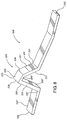
- FIG. 8-12 One embodiment of the present invention is represented in Figures 8-12 and comprises an external fixator assembly 200 including a support assembly generally indicated as 218.
- the external fixator assembly 200 is structured to be operatively positioned and used in a location substantially adjacent to the ankle area 12 of a patient as best represented in Figure 1 .
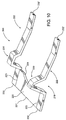
- the external fixator assembly 200 includes at least one but in many practical applications, two contoured segments 222 and 222' as respectively represented in Figures 8 and 9 .
- the base segment 220 defines at least a portion of the support assembly 218 and includes an inner peripheral edge or portion 221 having a substantially curvilinear configuration so as to accommodate placement of the heel or rear portion of the patient's foot, as also demonstrated in Figure 1 .
- the outer peripheral edge as at 221' may have a straight, linear configuration in contrast to the overall arcuate or semi-circular configuration of the base 20 of Figure 2 .
- the base segment 220 terminates at oppositely disposed free ends 223 and 223'. Each of the opposite ends 223 and 223' are fixedly and/or integrally connected to a lateral side portion 232" disposed adjacent the end 232 of each of the contoured segments 222 and 222'.
- the base 220 may also include a plurality of apertures or other structures 25, as represented in Figure 2 , which are positioned substantially along the length of the base segment 220. These apertures or appropriate structures 225 are provided to facilitate connection of one or more struts to the base segment 220 preferably using appropriate fixation bolts or other means of connection. As set forth above, such struts may facilitate the connection of the base 220 and/or the overall support assembly 218 to one or more halo-type rings. As is common, such halo-type rings extend along the length of the leg, generally above the ankle area 12 in surrounding relation to the bones 16 and 16', as described above with reference to Figure 1 .
- operative placement of the fixator assembly 200 comprises the supported disposition of one or both of the contoured segments 222 and 222' adjacent to an appropriate side of the ankle area 12.
- FIGs 8 and 9 it is emphasized that common structural features exist between each of the two contoured segments 222 and 222'. Further, each of a possible larger number of contoured segments may vary in dimension and configuration to accommodate accurate placement of a plurality of transfixion wires or members 36 relative to the ankle area 12 of different patients.
- each of the contoured segments 222 and 222' include a contoured portion generally indicated as 230.
- the contoured portion 230 of each of the contoured segments 222 and 222' is disposed in spaced relation to at least one end 232 thereof, but more practically in spaced or intermediate relation to the opposite ends 232 and 232' of corresponding ones of the contoured segments 222 and 222'.
- Each of the contoured portions 230 comprises a substantially angular, convergent configuration as the contoured portion 230 extends or protrudes transversely outward from a remainder of the length of a corresponding one of the contoured segments 222 and 222' and along the length or height of the ankle area 12.
- each of the contoured portions 230 comprise spaced apart legs 231 and 233 having there inner or proximal ends connected integrally or otherwise fixedly connected to the corresponding contoured segment 222 or 222', as at 237 and 237'.
- the outer or distal ends of each of the spaced apart legs 231 and 233 are integrally or fixedly connected to a bridge member 235, as at 238 and 238'.
- the bridge member 235 of each of the contoured portions 230 is disposed between and in interconnecting relation to the spaced apart arms 231 and 233 an integral junction or connection, 238 and 238'.
- FIG. 8 and 9 Another clearly distinguishing structural feature associated with the embodiments of the contoured segments 222 and 222' as represented in Figures 8 and 9 , as compared to the examples of Figures 1-7 , include each of the legs 231 and 233 as well as the bridge member 235 having an outer surface with a flat, substantially planar configuration extending along the respective lengths thereof.
- Such flat, substantially planar configurations are represented respectively as 231', 233' and 235' and are structured into this configuration so as to facilitate stable and secure connection, support and placement of at least one but more practically a plurality of transfixion members 36 in any one of a plurality of different orientations as the transfixion members 36 extend into supporting, stabilizing relation to the ankle area 12, as represented in the above described embodiment of Figure 5 .
- the flat, substantially planar configuration of the outer surfaces 231', 233' and 235' are not merely design choices but serve a specific, practical application by facilitating the stable placement, support and connection of the aforementioned transfixion members 36 at any point along the length of any one of the arms 231 or 233 as well as the bridge member 235.
- each of the arms 231 and 233 of each of the contoured protrusions 230 are arranged at a different angular orientation relative to one another and to the bridge member 235.
- the bridge member 235 and/or the outer surface 235' thereof is angularly inclined relative to each of the outer surfaces 231' and 233' of the respective arm members 231 and 233.
- a comparison between the embodiments of Figures 8 and 9 indicate a different "height" or distance of protrusion of the contoured portions 230 of the respective contoured segments 222 and 222'. As set forth above, this difference in heights of the contoured portions 230 facilitate a preferred positioning of the contoured segment 222 along the medial portion of the foot and the contoured segment 222' along the lateral portion of the foot and ankle.
- the plurality of transfixion wires, pins or members 36 may be located at different heights and orientations. At any of the different heights or varying angular orientations, the transfixion members 36 will be directed transversely inward into engaging relation to the intended bone or tissue of the ankle 12 which is being stabilized in the manner set forth above relating to the description of the embodiments of Figures 1 and 5 .
- each of the contoured segments 222 and 222' include the provision of a plurality of apertures 40 or other appropriately structured connecting sites extending along the length of each of the contoured portions 230 and possibly along the remainder of the length of the corresponding contoured segments 222 and 222'.
- These apertures 40 are clearly represented and described with regard to the embodiment of Figures 5 and 6 and are equally applicable to the embodiments of Figures 8-12 .
- these apertures 40 facilitate the interconnection of one or more transfixion members 36 thereto which facilitates the one or more transfixion members 36 being located at any one of a plurality of locations and/or orientations along the contoured portion 230 of each of the contoured segments 222 and 222'.
Landscapes
- Health & Medical Sciences (AREA)
- Orthopedic Medicine & Surgery (AREA)
- Life Sciences & Earth Sciences (AREA)
- Surgery (AREA)
- Biomedical Technology (AREA)
- Engineering & Computer Science (AREA)
- Nuclear Medicine, Radiotherapy & Molecular Imaging (AREA)
- Heart & Thoracic Surgery (AREA)
- Medical Informatics (AREA)
- Molecular Biology (AREA)
- Animal Behavior & Ethology (AREA)
- General Health & Medical Sciences (AREA)
- Public Health (AREA)
- Veterinary Medicine (AREA)
- Surgical Instruments (AREA)
Claims (13)
- Fixateur- bzw. Fixationsanordnung (200), die zur Anordnung benachbart zu einem Knöchelbereich (12) eines Patienten ausgelegt ist, wobei die Fixationsanordnung (200) Folgendes aufweist:eine Stütz- bzw. Halterungsanordnung (218), die benachbart eines Knöchelbereichs (12) angeordnet ist und aufgebaut ist, um zumindest ein Durchbohrungsglied (36) zu unterstützen, das sich in operativem Eingriff mit einem vorbestimmten Teil des Knöchelbereichs (12) befindet,wobei die Halterungsanordnung (218) zumindest ein Basissegment (220) und zumindest ein langgestrecktes, konturiertes Segment (222) aufweist, das mit dem Basissegment (220) verbunden ist,
wobei das zumindest eine konturierte Segment (222) einen konturierten Teil (230) aufweist, der entlang der Länge des einen konturierten Segments (222) und entlang der Länge des Knöchelgelenks angeordnet ist und sich quer dazu nach außen erstreckt, und
wobei das zumindest eine konturierte Segment (222) so aufgebaut ist, dass es das zumindest eine Durchbohrungsglied (36) in einer einer Vielzahl von unterschiedlichen Ausrichtungen relativ zu dem Knöchelbereich (12) anordnet,
wobei der konturierte Teil (230) langgestreckte, voneinander beabstandete Schenkelglieder (231, 233) und ein Brückenglied (235) aufweist, die in einer Zwischenverbindungsbeziehung zu den Schenkelgliedern (231, 233) angeordnet sind,
wobei das Brückenglied (235) und jedes der Schenkelglieder (231, 233) eine flache, im Wesentlichen planare Außenoberfläche (231', 233', 235') aufweisen, die sich entlang entsprechender Längen von diesen erstrecken, und
der konturierte Teil (230) so aufgebaut ist, dass er zumindest ein Durchbohrungsglied (36) in einer einer Vielzahl von unterschiedlichen Ausrichtungen relativ zu dem Knöchelbereich (12) trägt und anordnet;
dadurch gekennzeichnet, dass
der konturierte Teil (230) eine im Wesentlichen gewinkelte, konvergente Konfiguration aufweist, wenn sich der konturierte Teil (230) von dem Rest der Länge eines entsprechenden der konturierten Segmente (222, 222') und entlang der Länge oder der Höhe des Knöchelbereichs (12) erstreckt oder quer nach außen vorragt, wobei die gewinkelte Konfiguration zumindest teilweise durch eine nach außen vorragende, konvergente Konfiguration definiert wird,
wobei jedes der Schenkelglieder (231, 233) des konturierten Vorsprungs (230) mit einer unterschiedlichen Winkelausrichtung relativ zueinander und zu dem Brückenglied (235) angeordnet ist, und wobei das Brückenglied (235) und/oder die Außenoberfläche (235') von diesem angewinkelt relativ zu jeder der Außenoberflächen (231', 233') der entsprechenden Schenkelglieder (231, 233) geneigt ist. - Fixationsanordnung gemäß Anspruch 1, wobei das konturierte Segment (222) gegenüberliegend angeordnete Enden (232, 232') aufweist, wobei der konturierte Teil (230) in nach innenbeabstandeter Beziehung zu zumindest einem der gegenüberliegenden Enden (232, 232') angeordnet ist.
- Fixationsanordnung gemäß Anspruch 1, wobei das konturierte Segment (222) gegenüberliegend angeordneten Enden (232, 232') aufweist, wobei der konturierte Teil (230) in einer nach außen vorragenden, querverlaufenden Beziehung zu den Enden (232, 232') angeordnet ist.
- Fixationsanordnung gemäß Anspruch 3, wobei der konturierte Teil (230) eine im Wesentlichen konvergente Konfiguration aufweist, die so aufgebaut ist, dass sie das zumindest eine Durchbohrungsglied (36) an einer einer Vielzahl von Positionen zwischen den gegenüberliegenden Enden (232, 232') und entlang der Länge des Knöchelbereichs (12) verbindet.
- Fixationsanordnung gemäß Anspruch 4, wobei der konturierte Teil (230) in beabstandeter Beziehung zu zumindest einem der gegenüberliegenden Enden (232, 232') angeordnet ist,
wobei das konturierte Segment (222) so aufgebaut ist, dass es das zumindest eine Durchbohrungsglied (36) an einer einer Vielzahl von voneinander beabstandeten Positionen entlang einer Länge des konturierten Teils (230) und einen Rest des konturierten Segments (222) verbindet. - Fixationsanordnung gemäß Anspruch 3, wobei das Basissegment (220) mit einem der gegenüberliegenden Enden (232') des konturierten Segments (222) verbunden ist, wobei das andere der gegenüberliegenden Enden (232) des konturierten Segments (222) ein freies Ende von diesem definiert.
- Fixationsanordnung gemäß Anspruch 1, wobei das zumindest eine konturierte Segment (222) ferner ein Zwischensegment (50) aufweist, das in beabstandeter Beziehung zu dem konturierten Teil (230) und in einer Zwischenverbindungsbeziehung zwischen den verbleibenden Endteilen der Länge des zumindest einen konturierten Segments (222) angeordnet ist,
wobei das Zwischensegment (50) in im Wesentlichen axial ausgerichteter Beziehung zu den verbleibenden Endteilen des zumindest einen konturierten Segments (222) angeordnet ist,
wobei das Zwischensegment (50) integral an den verbleibenden Endteilen angebracht ist. - Fixationsanordnung gemäß Anspruch 1, wobei jede der Außenoberflächen (231', 233', 235') so aufgebaut ist, dass sie zumindest ein Durchbohrungsglied (36) in einer einer Vielzahl von unterschiedlichen Ausrichtungen auf dieser relativ zu dem Knöchelbereich (12) trägt und anordnet.
- Fixationsanordnung gemäß einem der vorangehenden Ansprüche, wobei:die Stütz- bzw. Halterungsanordnung (218) ein Basissegment (220) und zwei langgestreckte, konturierte Segmente (222) aufweist, die mit dem Basissegment (220) verbunden sind,jedes der konturierten Segmente (222) einen konturierten Teil (230) aufweist, der entlang und sich quer von dem entsprechenden der konturierten Segmente (222) nach außen und entlang der Länge des Knöchelbereichs (12) erstreckend angeordnet ist,jeder der konturierten Teile (230) langgestreckte, voneinander beabstandete Schenkelglieder (231, 233) und ein Brückenglied (235) aufweist, das in Zwischenverbindungsbeziehung zu den Schenkelgliedern (231, 233) angeordnet ist,jeder der konturierten Teile (230) so aufgebaut ist, dass er zumindest ein Durchbohrungsglied (36) an einer einer Vielzahl von beabstandeten Positionen entlang einer Länge des konturierten Teils (230) verbindet, undjedes der konturierten Teile (230) so aufgebaut und konfiguriert ist, dass es das zumindest eine Durchbohrungsglied (36) in einer quer nach innen verlaufenden Ausrichtung und in Eingriff mit dem Knöchelbereich (12) von irgendeiner einer Vielzahl von Positionen entlang der Länge des entsprechenden konturierten Teils (230) verbindet.
- Fixationsanordnung gemäß Anspruch 9, wobei das Brückenglied (235) und die Außenoberfläche (235') von diesem in einer angewinkelt geneigten Ausrichtung relativ zu der Länge des konturierten Segments (222) angeordnet sind.
- Fixationsanordnung gemäß Anspruch 9, wobei jedes der konturierten Segmente (222) gegenüberliegend angeordnete Enden (232, 232') aufweist, die mit einem der konturierten Teile (230) übereinstimmen, der zwischen den gegenüberliegenden Enden (232, 232') angeordnet ist.
- Fixationsanordnung gemäß Anspruch 9, wobei jeder der konturierten Teile (230) eine gewinkelte, im Wesentlichen konvergente Konfiguration aufweist, die sich von deinem Rest eines entsprechenden der konturierten Segmente (222) nach außen erstreckt, wobei jedes der Schenkelglieder (231, 233) jedes konturierten Teils (230) ein proximales Ende (237, 237'), das mit einem Rest eines entsprechenden der konturierten Segmente (222) verbunden ist, und ein distales Ende (238, 238') aufweist, das mit einem gegenüberliegenden Ende des entsprechenden Brückenglieds (235) verbunden ist.
- Fixationsanordnung gemäß Anspruch 9, wobei jedes der Brückenglieder (235) und das Schenkelglied (231, 232) eine Innenoberfläche (231", 233", 235") mit einer flachen, im Wesentlichen planaren Konfiguration aufweist, die sich entlang eines Großteils der entsprechenden Längen dieser erstrecken.
Applications Claiming Priority (2)
| Application Number | Priority Date | Filing Date | Title |
|---|---|---|---|
| US11/903,834 US7806843B2 (en) | 2007-09-25 | 2007-09-25 | External fixator assembly |
| PCT/US2008/011098 WO2009042167A1 (en) | 2007-09-25 | 2008-09-25 | External fixator assembly |
Publications (3)
| Publication Number | Publication Date |
|---|---|
| EP2194881A1 EP2194881A1 (de) | 2010-06-16 |
| EP2194881A4 EP2194881A4 (de) | 2013-11-20 |
| EP2194881B1 true EP2194881B1 (de) | 2016-11-09 |
Family
ID=40472493
Family Applications (1)
| Application Number | Title | Priority Date | Filing Date |
|---|---|---|---|
| EP08833815.7A Active EP2194881B1 (de) | 2007-09-25 | 2008-09-25 | Externe fixationsanordnung |
Country Status (3)
| Country | Link |
|---|---|
| US (3) | US7806843B2 (de) |
| EP (1) | EP2194881B1 (de) |
| WO (1) | WO2009042167A1 (de) |
Families Citing this family (16)
| Publication number | Priority date | Publication date | Assignee | Title |
|---|---|---|---|---|
| US7806843B2 (en) * | 2007-09-25 | 2010-10-05 | Marin Luis E | External fixator assembly |
| US20100179548A1 (en) | 2009-01-13 | 2010-07-15 | Marin Luis E | External fixator assembly |
| US8858555B2 (en) | 2009-10-05 | 2014-10-14 | Stryker Trauma Sa | Dynamic external fixator and methods for use |
| CA2783553C (en) | 2009-12-11 | 2017-10-17 | Small Bone Innovations, Inc. | Ankle fusion device, instrumentation and methods |
| US11141196B2 (en) | 2010-08-11 | 2021-10-12 | Stryker European Operations Holdings Llc | External fixator system |
| US8945128B2 (en) | 2010-08-11 | 2015-02-03 | Stryker Trauma Sa | External fixator system |
| EP2417923B1 (de) | 2010-08-11 | 2013-11-13 | Stryker Trauma SA | Externes Befestigungssystem |
| US9101398B2 (en) | 2012-08-23 | 2015-08-11 | Stryker Trauma Sa | Bone transport external fixation frame |
| US10463522B2 (en) | 2013-03-14 | 2019-11-05 | Mdpo Llc | Dynamic foot plate |
| US10993868B2 (en) | 2013-03-14 | 2021-05-04 | Mdpo Llc | Dynamic foot plate |
| US10980655B1 (en) | 2013-03-14 | 2021-04-20 | Mdpo Llc | Dynamic foot plate |
| WO2016040491A2 (en) | 2014-09-09 | 2016-03-17 | Integra Lifesciences Corporation | External fixation system |
| US10010350B2 (en) | 2016-06-14 | 2018-07-03 | Stryker European Holdings I, Llc | Gear mechanisms for fixation frame struts |
| WO2018140596A2 (en) | 2017-01-27 | 2018-08-02 | Arterys Inc. | Automated segmentation utilizing fully convolutional networks |
| US10874433B2 (en) | 2017-01-30 | 2020-12-29 | Stryker European Holdings I, Llc | Strut attachments for external fixation frame |
| BR112023001440A2 (pt) * | 2020-07-31 | 2023-02-14 | Bard Access Systems Inc | Configurações de válvula para uma válvula ajustável |
Family Cites Families (46)
| Publication number | Priority date | Publication date | Assignee | Title |
|---|---|---|---|---|
| US702389A (en) * | 1901-07-05 | 1902-06-17 | Frank O Anderson | Drawer-support. |
| US2079567A (en) * | 1932-08-22 | 1937-05-04 | Tower Company | Fracture reducing table |
| US2020262A (en) * | 1935-03-28 | 1935-11-05 | Harry Herschel Leiter | Surgical splint and reducing frame |
| US2035952A (en) * | 1935-05-20 | 1936-03-31 | Joe J Ettinger | Fracture reduction apparatus |
| US2393831A (en) * | 1942-12-29 | 1946-01-29 | Stader Otto | Bone splint |
| US2406987A (en) * | 1943-01-04 | 1946-09-03 | Anderson Roger | Fracture splint |
| US3941123A (en) * | 1975-05-20 | 1976-03-02 | Mstislav Vasilievich Volkov | Apparatus for joint movement restitution |
| IT1124715B (it) * | 1976-09-06 | 1986-05-14 | Alfa Romeo Spa | Impianto di iniezione intermittente di combustibile per motori a scoppio |
| CH630798A5 (fr) * | 1979-01-16 | 1982-07-15 | Jaquet Orthopedie | Fixateur externe pour osteosynthese. |
| US4308863A (en) * | 1979-10-18 | 1982-01-05 | Ace Orthopedic Manufacturing, Inc. | External fixation device |
| US4338927A (en) * | 1981-03-16 | 1982-07-13 | Volkov Mstislav V | Device for restoring the function of the lower extremities |
| US4696293A (en) * | 1982-09-30 | 1987-09-29 | Ciullo Jerome V | Hinged external fixator |
| US4624249A (en) * | 1984-12-04 | 1986-11-25 | Medicuba | Orthopedic external fixing apparatus |
| US4607625A (en) * | 1985-01-10 | 1986-08-26 | Schenck Robert R | Dynamic traction device |
| FR2595045B1 (fr) * | 1986-02-28 | 1991-12-27 | Hardy Jean Marie | Dispositif d'immobilisation d'un element osseux, notamment pour intervention orthopedique |
| DE3720242A1 (de) * | 1987-06-19 | 1988-12-29 | Schewior Thomas Dr Med | Ringfixateur zum einrichten von knochenabschnitten und/oder -fragmenten und zum erzeugen von knochen-spannlagen |
| JPH03502535A (ja) * | 1988-07-25 | 1991-06-13 | フセソユズニ クルガンスキ ナウチニ ツェントル“ボススタノビテルナヤ トラフマトロギア イ オルトペディア” | 手の形成的復元のための伸延装置 |
| US5062844A (en) * | 1990-09-07 | 1991-11-05 | Smith & Nephew Richards Inc. | Method and apparatus for the fixation of bone fractures, limb lengthening and the correction of deformities |
| DE59406392D1 (de) * | 1993-02-18 | 1998-08-13 | Endocare Ag | Vorrichtung zur verlängerung von knochen |
| US5766173A (en) * | 1993-06-10 | 1998-06-16 | Texas Scottish Rite Hospital For Children | Distractor mechanism for external fixation device |
| US5496319A (en) * | 1994-06-27 | 1996-03-05 | Zimmer, Inc. | External fixation apparatus |
| US5578041A (en) * | 1994-10-14 | 1996-11-26 | Trustees Of The University Of Pennsylvania | External fixation device |
| EP0814714B1 (de) * | 1995-03-01 | 2005-10-05 | Smith & Nephew, Inc. | Räumlicher rahmen |
| US5743898A (en) * | 1995-05-12 | 1998-04-28 | Electro-Biology, Inc. | Method and apparatus for external fixation of small bones |
| US5776132A (en) * | 1996-12-26 | 1998-07-07 | Blyakher; Arkady | External fixation assembly |
| GB2324038A (en) * | 1997-04-11 | 1998-10-14 | Univ Keele | Fracture reduction device |
| US5891143A (en) * | 1997-10-20 | 1999-04-06 | Smith & Nephew, Inc. | Orthopaedic fixation plate |
| US5931837A (en) * | 1997-12-09 | 1999-08-03 | University Of Iowa Research Foundation | Method and apparatus for external fixation of an ankle |
| US6030386A (en) * | 1998-08-10 | 2000-02-29 | Smith & Nephew, Inc. | Six axis external fixator strut |
| WO2000040163A1 (en) * | 1998-12-31 | 2000-07-13 | Orthofix S.R.L. | Improved device for the external fixation of bones fractures, in particular ankle fractures |
| US20020010465A1 (en) * | 2000-01-31 | 2002-01-24 | Ja Kyo Koo | Frame fixator and operation system thereof |
| US6355037B1 (en) * | 2000-12-05 | 2002-03-12 | Smith & Nephew, Inc. | Apparatus and method of external skeletal support allowing for internal-external rotation |
| US7048735B2 (en) * | 2002-02-04 | 2006-05-23 | Smith & Nephew | External fixation system |
| US7025790B2 (en) * | 2002-06-27 | 2006-04-11 | Concepts In Medicine Iii, L.L.C. | Ankle joint prosthesis and its method of implantation |
| KR20050083916A (ko) * | 2002-11-19 | 2005-08-26 | 어큠드 엘엘씨 | 변형가능한 뼈 평판 |
| US7608074B2 (en) * | 2003-01-10 | 2009-10-27 | Smith & Nephew, Inc. | External fixation apparatus and method |
| US7114744B2 (en) | 2003-02-20 | 2006-10-03 | Nissan Motor Co., Ltd. | Airbag apparatus and related method |
| US7615051B2 (en) * | 2003-02-21 | 2009-11-10 | Synthes Usa, Llc | Craniofacial fracture reduction assembly |
| US6964663B2 (en) * | 2003-09-16 | 2005-11-15 | Ez Concepts Surgical Device Corporation | Combination bone fixation/immobilization apparatus |
| US7361176B2 (en) * | 2003-12-31 | 2008-04-22 | Depuy Products, Inc. | External bone/joint fixation device |
| US7465303B2 (en) * | 2004-04-22 | 2008-12-16 | Wright Medical Technology, Inc. | External fixation assembly |
| US7306601B2 (en) * | 2005-06-10 | 2007-12-11 | Quantum Medical Concepts, Inc. | External fixation system with provisional brace |
| US7422593B2 (en) * | 2005-12-08 | 2008-09-09 | Ebi, L.P. | External fixation system |
| US7806843B2 (en) * | 2007-09-25 | 2010-10-05 | Marin Luis E | External fixator assembly |
| US7887495B2 (en) * | 2007-10-18 | 2011-02-15 | Boyd Lawrence M | Protective and cosmetic covering for external fixators |
| US20100179548A1 (en) * | 2009-01-13 | 2010-07-15 | Marin Luis E | External fixator assembly |
-
2007
- 2007-09-25 US US11/903,834 patent/US7806843B2/en active Active
-
2008
- 2008-09-25 US US12/284,891 patent/US7887498B2/en active Active
- 2008-09-25 WO PCT/US2008/011098 patent/WO2009042167A1/en not_active Ceased
- 2008-09-25 EP EP08833815.7A patent/EP2194881B1/de active Active
-
2011
- 2011-02-15 US US13/027,674 patent/US8251937B2/en active Active
Also Published As
| Publication number | Publication date |
|---|---|
| US8251937B2 (en) | 2012-08-28 |
| US20090177197A1 (en) | 2009-07-09 |
| US7806843B2 (en) | 2010-10-05 |
| EP2194881A4 (de) | 2013-11-20 |
| WO2009042167A1 (en) | 2009-04-02 |
| US20090082709A1 (en) | 2009-03-26 |
| US20110208186A1 (en) | 2011-08-25 |
| US7887498B2 (en) | 2011-02-15 |
| EP2194881A1 (de) | 2010-06-16 |
Similar Documents
| Publication | Publication Date | Title |
|---|---|---|
| US7887498B2 (en) | External fixator assembly | |
| US9924968B2 (en) | External fixator assembly | |
| US9265528B2 (en) | Orthopedic fixation systems and methods | |
| US20240032977A1 (en) | Bone fixation system, assembly, implants, devices, alignment guides, and methods of use | |
| US9265529B2 (en) | Orthopedic fixation systems and methods | |
| US10327829B2 (en) | Alignment guide apparatus, methods and systems | |
| US6964663B2 (en) | Combination bone fixation/immobilization apparatus | |
| US20040073212A1 (en) | Extracorporeal fixing device for a bone fracture | |
| US20080082101A1 (en) | Implant, implant system, and use of an implant and implant system | |
| BRPI0714325A2 (pt) | placa calcaneana | |
| KR20060002767A (ko) | 두개안면 골절 교정 조립체 | |
| WO2004045451A2 (en) | Apparatus and method for maintaining bones in a healing position | |
| JP6925656B2 (ja) | 創外固定器 | |
| US11589900B2 (en) | Modular frame | |
| US10806493B2 (en) | Sadat fixation device and method | |
| US20220022917A1 (en) | External fixator for bone fractures | |
| US20240065739A1 (en) | Rescue external fixation system | |
| ES2260190T3 (es) | Un forceps utilizado para la reduccion quirurgica de huesos faciales fracturados. | |
| US20220296277A1 (en) | Rescue ring | |
| US20220280194A1 (en) | Connection device | |
| CN221383742U (zh) | 螺钉水平置入引导装置 | |
| US11484344B2 (en) | Locking device for an external fixator for bone fracture | |
| WO2014105742A1 (en) | Orthopedic bone plate and locking tab apparatus and method of use | |
| WO2020128581A1 (en) | External fixator for bone fractures |
Legal Events
| Date | Code | Title | Description |
|---|---|---|---|
| PUAI | Public reference made under article 153(3) epc to a published international application that has entered the european phase |
Free format text: ORIGINAL CODE: 0009012 |
|
| 17P | Request for examination filed |
Effective date: 20100324 |
|
| AK | Designated contracting states |
Kind code of ref document: A1 Designated state(s): AT BE BG CH CY CZ DE DK EE ES FI FR GB GR HR HU IE IS IT LI LT LU LV MC MT NL NO PL PT RO SE SI SK TR |
|
| AX | Request for extension of the european patent |
Extension state: AL BA MK RS |
|
| DAX | Request for extension of the european patent (deleted) | ||
| A4 | Supplementary search report drawn up and despatched |
Effective date: 20131023 |
|
| RIC1 | Information provided on ipc code assigned before grant |
Ipc: A61B 17/64 20060101ALI20131017BHEP Ipc: A61B 17/00 20060101AFI20131017BHEP |
|
| 17Q | First examination report despatched |
Effective date: 20150107 |
|
| 17Q | First examination report despatched |
Effective date: 20150107 |
|
| GRAP | Despatch of communication of intention to grant a patent |
Free format text: ORIGINAL CODE: EPIDOSNIGR1 |
|
| INTG | Intention to grant announced |
Effective date: 20160419 |
|
| GRAS | Grant fee paid |
Free format text: ORIGINAL CODE: EPIDOSNIGR3 |
|
| GRAA | (expected) grant |
Free format text: ORIGINAL CODE: 0009210 |
|
| AK | Designated contracting states |
Kind code of ref document: B1 Designated state(s): AT BE BG CH CY CZ DE DK EE ES FI FR GB GR HR HU IE IS IT LI LT LU LV MC MT NL NO PL PT RO SE SI SK TR |
|
| REG | Reference to a national code |
Ref country code: GB Ref legal event code: FG4D |
|
| REG | Reference to a national code |
Ref country code: AT Ref legal event code: REF Ref document number: 843132 Country of ref document: AT Kind code of ref document: T Effective date: 20161115 Ref country code: CH Ref legal event code: EP |
|
| REG | Reference to a national code |
Ref country code: IE Ref legal event code: FG4D |
|
| REG | Reference to a national code |
Ref country code: DE Ref legal event code: R096 Ref document number: 602008047311 Country of ref document: DE |
|
| PG25 | Lapsed in a contracting state [announced via postgrant information from national office to epo] |
Ref country code: LV Free format text: LAPSE BECAUSE OF FAILURE TO SUBMIT A TRANSLATION OF THE DESCRIPTION OR TO PAY THE FEE WITHIN THE PRESCRIBED TIME-LIMIT Effective date: 20161109 |
|
| REG | Reference to a national code |
Ref country code: LT Ref legal event code: MG4D |
|
| REG | Reference to a national code |
Ref country code: NL Ref legal event code: MP Effective date: 20161109 |
|
| REG | Reference to a national code |
Ref country code: AT Ref legal event code: MK05 Ref document number: 843132 Country of ref document: AT Kind code of ref document: T Effective date: 20161109 |
|
| PG25 | Lapsed in a contracting state [announced via postgrant information from national office to epo] |
Ref country code: NO Free format text: LAPSE BECAUSE OF FAILURE TO SUBMIT A TRANSLATION OF THE DESCRIPTION OR TO PAY THE FEE WITHIN THE PRESCRIBED TIME-LIMIT Effective date: 20170209 Ref country code: SE Free format text: LAPSE BECAUSE OF FAILURE TO SUBMIT A TRANSLATION OF THE DESCRIPTION OR TO PAY THE FEE WITHIN THE PRESCRIBED TIME-LIMIT Effective date: 20161109 Ref country code: LT Free format text: LAPSE BECAUSE OF FAILURE TO SUBMIT A TRANSLATION OF THE DESCRIPTION OR TO PAY THE FEE WITHIN THE PRESCRIBED TIME-LIMIT Effective date: 20161109 Ref country code: NL Free format text: LAPSE BECAUSE OF FAILURE TO SUBMIT A TRANSLATION OF THE DESCRIPTION OR TO PAY THE FEE WITHIN THE PRESCRIBED TIME-LIMIT Effective date: 20161109 Ref country code: GR Free format text: LAPSE BECAUSE OF FAILURE TO SUBMIT A TRANSLATION OF THE DESCRIPTION OR TO PAY THE FEE WITHIN THE PRESCRIBED TIME-LIMIT Effective date: 20170210 |
|
| PG25 | Lapsed in a contracting state [announced via postgrant information from national office to epo] |
Ref country code: AT Free format text: LAPSE BECAUSE OF FAILURE TO SUBMIT A TRANSLATION OF THE DESCRIPTION OR TO PAY THE FEE WITHIN THE PRESCRIBED TIME-LIMIT Effective date: 20161109 Ref country code: ES Free format text: LAPSE BECAUSE OF FAILURE TO SUBMIT A TRANSLATION OF THE DESCRIPTION OR TO PAY THE FEE WITHIN THE PRESCRIBED TIME-LIMIT Effective date: 20161109 Ref country code: HR Free format text: LAPSE BECAUSE OF FAILURE TO SUBMIT A TRANSLATION OF THE DESCRIPTION OR TO PAY THE FEE WITHIN THE PRESCRIBED TIME-LIMIT Effective date: 20161109 Ref country code: FI Free format text: LAPSE BECAUSE OF FAILURE TO SUBMIT A TRANSLATION OF THE DESCRIPTION OR TO PAY THE FEE WITHIN THE PRESCRIBED TIME-LIMIT Effective date: 20161109 Ref country code: PL Free format text: LAPSE BECAUSE OF FAILURE TO SUBMIT A TRANSLATION OF THE DESCRIPTION OR TO PAY THE FEE WITHIN THE PRESCRIBED TIME-LIMIT Effective date: 20161109 Ref country code: IS Free format text: LAPSE BECAUSE OF FAILURE TO SUBMIT A TRANSLATION OF THE DESCRIPTION OR TO PAY THE FEE WITHIN THE PRESCRIBED TIME-LIMIT Effective date: 20170309 Ref country code: PT Free format text: LAPSE BECAUSE OF FAILURE TO SUBMIT A TRANSLATION OF THE DESCRIPTION OR TO PAY THE FEE WITHIN THE PRESCRIBED TIME-LIMIT Effective date: 20170309 |
|
| PG25 | Lapsed in a contracting state [announced via postgrant information from national office to epo] |
Ref country code: CZ Free format text: LAPSE BECAUSE OF FAILURE TO SUBMIT A TRANSLATION OF THE DESCRIPTION OR TO PAY THE FEE WITHIN THE PRESCRIBED TIME-LIMIT Effective date: 20161109 Ref country code: RO Free format text: LAPSE BECAUSE OF FAILURE TO SUBMIT A TRANSLATION OF THE DESCRIPTION OR TO PAY THE FEE WITHIN THE PRESCRIBED TIME-LIMIT Effective date: 20161109 Ref country code: SK Free format text: LAPSE BECAUSE OF FAILURE TO SUBMIT A TRANSLATION OF THE DESCRIPTION OR TO PAY THE FEE WITHIN THE PRESCRIBED TIME-LIMIT Effective date: 20161109 Ref country code: DK Free format text: LAPSE BECAUSE OF FAILURE TO SUBMIT A TRANSLATION OF THE DESCRIPTION OR TO PAY THE FEE WITHIN THE PRESCRIBED TIME-LIMIT Effective date: 20161109 Ref country code: EE Free format text: LAPSE BECAUSE OF FAILURE TO SUBMIT A TRANSLATION OF THE DESCRIPTION OR TO PAY THE FEE WITHIN THE PRESCRIBED TIME-LIMIT Effective date: 20161109 |
|
| REG | Reference to a national code |
Ref country code: DE Ref legal event code: R097 Ref document number: 602008047311 Country of ref document: DE |
|
| PG25 | Lapsed in a contracting state [announced via postgrant information from national office to epo] |
Ref country code: BE Free format text: LAPSE BECAUSE OF FAILURE TO SUBMIT A TRANSLATION OF THE DESCRIPTION OR TO PAY THE FEE WITHIN THE PRESCRIBED TIME-LIMIT Effective date: 20161109 Ref country code: BG Free format text: LAPSE BECAUSE OF FAILURE TO SUBMIT A TRANSLATION OF THE DESCRIPTION OR TO PAY THE FEE WITHIN THE PRESCRIBED TIME-LIMIT Effective date: 20170209 |
|
| PLBE | No opposition filed within time limit |
Free format text: ORIGINAL CODE: 0009261 |
|
| STAA | Information on the status of an ep patent application or granted ep patent |
Free format text: STATUS: NO OPPOSITION FILED WITHIN TIME LIMIT |
|
| 26N | No opposition filed |
Effective date: 20170810 |
|
| PG25 | Lapsed in a contracting state [announced via postgrant information from national office to epo] |
Ref country code: SI Free format text: LAPSE BECAUSE OF FAILURE TO SUBMIT A TRANSLATION OF THE DESCRIPTION OR TO PAY THE FEE WITHIN THE PRESCRIBED TIME-LIMIT Effective date: 20161109 |
|
| REG | Reference to a national code |
Ref country code: CH Ref legal event code: PL |
|
| PG25 | Lapsed in a contracting state [announced via postgrant information from national office to epo] |
Ref country code: MC Free format text: LAPSE BECAUSE OF FAILURE TO SUBMIT A TRANSLATION OF THE DESCRIPTION OR TO PAY THE FEE WITHIN THE PRESCRIBED TIME-LIMIT Effective date: 20161109 |
|
| REG | Reference to a national code |
Ref country code: IE Ref legal event code: MM4A |
|
| PG25 | Lapsed in a contracting state [announced via postgrant information from national office to epo] |
Ref country code: LU Free format text: LAPSE BECAUSE OF NON-PAYMENT OF DUE FEES Effective date: 20170925 |
|
| REG | Reference to a national code |
Ref country code: FR Ref legal event code: ST Effective date: 20180531 |
|
| PG25 | Lapsed in a contracting state [announced via postgrant information from national office to epo] |
Ref country code: IE Free format text: LAPSE BECAUSE OF NON-PAYMENT OF DUE FEES Effective date: 20170925 Ref country code: LI Free format text: LAPSE BECAUSE OF NON-PAYMENT OF DUE FEES Effective date: 20170930 Ref country code: CH Free format text: LAPSE BECAUSE OF NON-PAYMENT OF DUE FEES Effective date: 20170930 |
|
| PG25 | Lapsed in a contracting state [announced via postgrant information from national office to epo] |
Ref country code: IT Free format text: LAPSE BECAUSE OF NON-PAYMENT OF DUE FEES Effective date: 20170925 Ref country code: FR Free format text: LAPSE BECAUSE OF NON-PAYMENT OF DUE FEES Effective date: 20171002 |
|
| PG25 | Lapsed in a contracting state [announced via postgrant information from national office to epo] |
Ref country code: MT Free format text: LAPSE BECAUSE OF NON-PAYMENT OF DUE FEES Effective date: 20170925 |
|
| PG25 | Lapsed in a contracting state [announced via postgrant information from national office to epo] |
Ref country code: HU Free format text: LAPSE BECAUSE OF FAILURE TO SUBMIT A TRANSLATION OF THE DESCRIPTION OR TO PAY THE FEE WITHIN THE PRESCRIBED TIME-LIMIT; INVALID AB INITIO Effective date: 20080925 |
|
| PG25 | Lapsed in a contracting state [announced via postgrant information from national office to epo] |
Ref country code: CY Free format text: LAPSE BECAUSE OF NON-PAYMENT OF DUE FEES Effective date: 20161109 |
|
| PG25 | Lapsed in a contracting state [announced via postgrant information from national office to epo] |
Ref country code: TR Free format text: LAPSE BECAUSE OF FAILURE TO SUBMIT A TRANSLATION OF THE DESCRIPTION OR TO PAY THE FEE WITHIN THE PRESCRIBED TIME-LIMIT Effective date: 20161109 |
|
| PGFP | Annual fee paid to national office [announced via postgrant information from national office to epo] |
Ref country code: GB Payment date: 20250930 Year of fee payment: 18 |
|
| PGFP | Annual fee paid to national office [announced via postgrant information from national office to epo] |
Ref country code: DE Payment date: 20250930 Year of fee payment: 18 |