EP2195532B1 - Centrale thermodynamique - Google Patents
Centrale thermodynamique Download PDFInfo
- Publication number
- EP2195532B1 EP2195532B1 EP08808023.9A EP08808023A EP2195532B1 EP 2195532 B1 EP2195532 B1 EP 2195532B1 EP 08808023 A EP08808023 A EP 08808023A EP 2195532 B1 EP2195532 B1 EP 2195532B1
- Authority
- EP
- European Patent Office
- Prior art keywords
- power plant
- solar
- fluid
- turbine
- thermal
- Prior art date
- Legal status (The legal status is an assumption and is not a legal conclusion. Google has not performed a legal analysis and makes no representation as to the accuracy of the status listed.)
- Not-in-force
Links
- 239000012530 fluid Substances 0.000 claims description 125
- 239000006100 radiation absorber Substances 0.000 claims description 25
- 230000005855 radiation Effects 0.000 claims description 16
- XLYOFNOQVPJJNP-UHFFFAOYSA-N water Substances O XLYOFNOQVPJJNP-UHFFFAOYSA-N 0.000 claims description 9
- 238000012546 transfer Methods 0.000 claims description 8
- CURLTUGMZLYLDI-UHFFFAOYSA-N Carbon dioxide Chemical compound O=C=O CURLTUGMZLYLDI-UHFFFAOYSA-N 0.000 claims description 6
- 239000006096 absorbing agent Substances 0.000 claims description 4
- 229910002092 carbon dioxide Inorganic materials 0.000 claims description 3
- 239000001569 carbon dioxide Substances 0.000 claims description 3
- 229910052734 helium Inorganic materials 0.000 claims description 3
- 239000001307 helium Substances 0.000 claims description 3
- SWQJXJOGLNCZEY-UHFFFAOYSA-N helium atom Chemical compound [He] SWQJXJOGLNCZEY-UHFFFAOYSA-N 0.000 claims description 3
- 238000000034 method Methods 0.000 claims description 3
- 150000003839 salts Chemical class 0.000 claims description 3
- 239000003921 oil Substances 0.000 claims 1
- 238000010248 power generation Methods 0.000 claims 1
- 238000010438 heat treatment Methods 0.000 description 8
- 238000004891 communication Methods 0.000 description 5
- 238000011144 upstream manufacturing Methods 0.000 description 3
- 230000008901 benefit Effects 0.000 description 2
- 230000005611 electricity Effects 0.000 description 2
- 239000011521 glass Substances 0.000 description 2
- 239000007788 liquid Substances 0.000 description 2
- 230000007257 malfunction Effects 0.000 description 2
- 238000003303 reheating Methods 0.000 description 2
- 238000010521 absorption reaction Methods 0.000 description 1
- 230000002411 adverse Effects 0.000 description 1
- 238000013459 approach Methods 0.000 description 1
- 239000011248 coating agent Substances 0.000 description 1
- 238000000576 coating method Methods 0.000 description 1
- 239000012141 concentrate Substances 0.000 description 1
- 238000010276 construction Methods 0.000 description 1
- 230000008878 coupling Effects 0.000 description 1
- 238000010168 coupling process Methods 0.000 description 1
- 238000005859 coupling reaction Methods 0.000 description 1
- 238000010586 diagram Methods 0.000 description 1
- 239000000446 fuel Substances 0.000 description 1
- 238000002955 isolation Methods 0.000 description 1
- 238000012423 maintenance Methods 0.000 description 1
- 239000002184 metal Substances 0.000 description 1
- 238000012986 modification Methods 0.000 description 1
- 230000004048 modification Effects 0.000 description 1
- 125000001997 phenyl group Chemical group [H]C1=C([H])C([H])=C(*)C([H])=C1[H] 0.000 description 1
- 238000005086 pumping Methods 0.000 description 1
- 230000000630 rising effect Effects 0.000 description 1
- 229920006395 saturated elastomer Polymers 0.000 description 1
- 239000006163 transport media Substances 0.000 description 1
- 238000010792 warming Methods 0.000 description 1
Images

Classifications
-
- F—MECHANICAL ENGINEERING; LIGHTING; HEATING; WEAPONS; BLASTING
- F01—MACHINES OR ENGINES IN GENERAL; ENGINE PLANTS IN GENERAL; STEAM ENGINES
- F01K—STEAM ENGINE PLANTS; STEAM ACCUMULATORS; ENGINE PLANTS NOT OTHERWISE PROVIDED FOR; ENGINES USING SPECIAL WORKING FLUIDS OR CYCLES
- F01K7/00—Steam engine plants characterised by the use of specific types of engine; Plants or engines characterised by their use of special steam systems, cycles or processes; Control means specially adapted for such systems, cycles or processes; Use of withdrawn or exhaust steam for feed-water heating
- F01K7/16—Steam engine plants characterised by the use of specific types of engine; Plants or engines characterised by their use of special steam systems, cycles or processes; Control means specially adapted for such systems, cycles or processes; Use of withdrawn or exhaust steam for feed-water heating the engines being only of turbine type
- F01K7/22—Steam engine plants characterised by the use of specific types of engine; Plants or engines characterised by their use of special steam systems, cycles or processes; Control means specially adapted for such systems, cycles or processes; Use of withdrawn or exhaust steam for feed-water heating the engines being only of turbine type the turbines having inter-stage steam heating
-
- F—MECHANICAL ENGINEERING; LIGHTING; HEATING; WEAPONS; BLASTING
- F01—MACHINES OR ENGINES IN GENERAL; ENGINE PLANTS IN GENERAL; STEAM ENGINES
- F01K—STEAM ENGINE PLANTS; STEAM ACCUMULATORS; ENGINE PLANTS NOT OTHERWISE PROVIDED FOR; ENGINES USING SPECIAL WORKING FLUIDS OR CYCLES
- F01K25/00—Plants or engines characterised by use of special working fluids, not otherwise provided for; Plants operating in closed cycles and not otherwise provided for
- F01K25/08—Plants or engines characterised by use of special working fluids, not otherwise provided for; Plants operating in closed cycles and not otherwise provided for using special vapours
-
- F—MECHANICAL ENGINEERING; LIGHTING; HEATING; WEAPONS; BLASTING
- F03—MACHINES OR ENGINES FOR LIQUIDS; WIND, SPRING, OR WEIGHT MOTORS; PRODUCING MECHANICAL POWER OR A REACTIVE PROPULSIVE THRUST, NOT OTHERWISE PROVIDED FOR
- F03G—SPRING, WEIGHT, INERTIA OR LIKE MOTORS; MECHANICAL-POWER PRODUCING DEVICES OR MECHANISMS, NOT OTHERWISE PROVIDED FOR OR USING ENERGY SOURCES NOT OTHERWISE PROVIDED FOR
- F03G6/00—Devices for producing mechanical power from solar energy
- F03G6/06—Devices for producing mechanical power from solar energy with solar energy concentrating means
- F03G6/065—Devices for producing mechanical power from solar energy with solar energy concentrating means having a Rankine cycle
- F03G6/067—Binary cycle plants where the fluid from the solar collector heats the working fluid via a heat exchanger
-
- F—MECHANICAL ENGINEERING; LIGHTING; HEATING; WEAPONS; BLASTING
- F03—MACHINES OR ENGINES FOR LIQUIDS; WIND, SPRING, OR WEIGHT MOTORS; PRODUCING MECHANICAL POWER OR A REACTIVE PROPULSIVE THRUST, NOT OTHERWISE PROVIDED FOR
- F03G—SPRING, WEIGHT, INERTIA OR LIKE MOTORS; MECHANICAL-POWER PRODUCING DEVICES OR MECHANISMS, NOT OTHERWISE PROVIDED FOR OR USING ENERGY SOURCES NOT OTHERWISE PROVIDED FOR
- F03G6/00—Devices for producing mechanical power from solar energy
- F03G6/098—Components, parts or details
- F03G6/108—Components, parts or details of the heat transfer system
- F03G6/111—Heat transfer fluids
- F03G6/114—Molten salts
-
- Y—GENERAL TAGGING OF NEW TECHNOLOGICAL DEVELOPMENTS; GENERAL TAGGING OF CROSS-SECTIONAL TECHNOLOGIES SPANNING OVER SEVERAL SECTIONS OF THE IPC; TECHNICAL SUBJECTS COVERED BY FORMER USPC CROSS-REFERENCE ART COLLECTIONS [XRACs] AND DIGESTS
- Y02—TECHNOLOGIES OR APPLICATIONS FOR MITIGATION OR ADAPTATION AGAINST CLIMATE CHANGE
- Y02E—REDUCTION OF GREENHOUSE GAS [GHG] EMISSIONS, RELATED TO ENERGY GENERATION, TRANSMISSION OR DISTRIBUTION
- Y02E10/00—Energy generation through renewable energy sources
- Y02E10/40—Solar thermal energy, e.g. solar towers
- Y02E10/46—Conversion of thermal power into mechanical power, e.g. Rankine, Stirling or solar thermal engines
Definitions
- This invention relates to solar thermal power plants, and in particular, to solar thermal power plants which provide thermal energy to steam-electric power generating plants.
- One type of solar power plant utilizes a "radiation concentrator collector” which concentrates the solar radiation by focusing it onto a smaller area, e.g., using mirrored surfaces or lenses.
- a reflector which is typically parabolic, receives and reflects (focuses) incoming solar radiation onto a radiation absorber, which is formed as a tube.
- the tube radiation absorber is concentrically surrounded by a treated glass enclosure tube to limit the loss of heat.
- the collector system further includes means to track the sun.
- Such a solar thermal power plant is known from EP-A-0 526 816 .
- the space between the tube radiation absorber and the glass enclosure tube is evacuated to very low pressure.
- the tube radiation absorber is made of metal with a coating having a high solar radiation absorption coefficient to maximize the energy transfer imparted by the solar radiation reflecting off the reflector.
- a thermal fluid constituting a heat transport medium which is typically a liquid such as oil, flows within the tube radiation absorber.
- the thermal energy transported by the thermal fluid is then is used to power a steamelectric power plant to drive one or more turbines, in order to generate electricity in a conventional way, e.g., by coupling the axle of each of the turbines to a generator.
- the solar thermal power plant known from EP-A-0 526 816 comprises a steam-electric power plant.
- the steam-electric power plant comprises an intermediate-pressure steam turbine, a low-pressure steam turbine and an additional steam turbine having an inlet pressure higher than that of the intermediate-pressure steam turbine.
- the steam-electric power plant comprises piping containing a working fluid. Each turbine being associated with a heat exchange system adapted to transfer heat from said thermal fluid to said working fluid.
- thermal fluids may dissociate or otherwise break down or become less effective at transferring heat. Accordingly, such solar thermal energy generating plants are typically limited to operate at temperatures below this threshold, which for some thermal fluids may be in the region of about 400°C.
- a solar thermal power plant comprising a solar collection system and a steam-electric power plant, wherein the solar collection system comprises one or more tube radiation absorbers containing a thermal fluid therewithin, the system being configured to heat said thermal fluid by passing the thermal fluid through said one or more tube radiation absorbers while said absorbers are irradiated with solar radiation, either direct, reflected, or both;
- the steam-electric power plant comprises an intermediate-pressure steam turbine, a low-pressure steam turbine, and at least one additional steam turbine having an inlet pressure which is higher than that of the intermediate-pressure steam turbine, and piping containing a working fluid; each turbine being associated with and connected upstream thereof to a heat exchange system adapted to transfer heat from said thermal fluid to said working fluid.
- the solar thermal power plant is characterized in that the heat exchange system associated with said additional steam turbine comprises three heat exchangers, a first being a pre-heater, a second being an evaporator, and a third being a superheater.
- the thermal fluid may be thermal oil or steam/water.
- the working fluid may be molten salts, carbon dioxide, or helium.
- the solar collection system may further comprise trough collectors, which may be, e.g., single-axis sun-tracking parabolic reflectors or linear Fresnel collectors.
- the working fluid of the steam-electric power plant may be steam/water.
- the solar thermal power plant may have an operating temperature below about 400°C.
- the heat exchange system associated with the additional steam turbine may comprises three heat exchangers, a first being a pre-heater, a second being an evaporator, and a third being a super-heater.
- the solar thermal power plant may comprise one additional turbine, wherein the inlet pressures of the additional turbine, the intermediate-pressure turbine, and the low-pressure turbine are about, respectively, 150 bar, 100 bar, and 20 bar.
- the thermal power plant may have a gross Rankine efficiency which is substantially or exceeds 42%.
- the solar thermal power plant may further comprise a controller adapted to control distribution of the thermal fluid to each of the heat exchange systems such that the efficiency of the plant is optimized.
- the tube radiation absorbers may be disposed within evacuated transparent tubes, at least within the solar collection system.
- the heat exchange system associated with the intermediate-pressure turbine may constitute a first reheater, and the heat exchange system associated with the low pressure turbine may constitute a second reheater.
- thermo fluid is heated to a temperature not exceeding approximately 400°C. Consequently, the operating temperature of the steam-electric power plant does not exceed approximately 400°C.
- a method for generating power by using the described solar thermal power plant comprising:
- the tube radiation absorbers may constitute a portion of a solar collection system of a solar thermal power plant comprising the solar collection system and a steam-electric power plant.
- the solar collection system may further comprise trough collectors, which may be single-axis sun-tracking parabolic reflectors or linear Fresnel collectors.
- the working fluid of the steam-electric power plant may be water/steam.
- the heat exchange system associated with the additional steam turbine may comprises three heat exchangers, a first being a pre-heater, a second being an evaporator, and a third being a super-heater.
- the solar thermal power plant may comprise one additional turbine, wherein the inlet pressures of the turbines are 150 bar, 60 bar, and 20 bar.
- the thermal power plant may have a gross Rankine efficiency which approaches or exceeds 42%.
- the solar thermal power plant may further comprise a controller adapted to control distribution of the thermal fluid to each of the heat exchange systems such that the efficiency of the plant is optimized.
- the heat exchange system associated with the intermediate-pressure turbine may constitute a first reheater, and the heat exchange system associated with the low pressure turbine may constitute a second reheater.
- the tube radiation absorbers may be disposed within evacuated transparent tubes.
- the thermal fluid may have a maximum operating temperature of about 400°C.
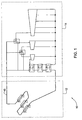
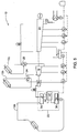
- a solar thermal power plant which is generally indicated at 10, according to a first embodiment of the present invention.
- the plant 10 comprises a solar collection system 12 and a steam-electric power plant 14.
- the plant further comprises a heating circuit 13, which comprises one or more tube radiation absorbers 15 (which also constitute a portion of the solar collection system 12 ).
- the solar collection system 12 comprises one or more tube radiation absorbers 15 and a plurality of trough collectors 17, such as single-axis parabolic reflectors.
- any suitable means for concentrating solar radiation such as Fresnel collectors, may be provided.
- the tubes including those which are not exposed to solar radiation, constitute a heating circuit of the plant 10.
- the tube radiation absorbers contain a thermal fluid therein, such as oil (phenyls) which are commercially available, such as under the trade name Therminol® VP-1.
- the thermal fluid may also be one of steam/water, molten salts, carbon dioxide, and helium.
- the thermal fluid is heated within the tubes upon their exposure to direct and concentrated solar radiation.
- the thermal fluid is heated as it flows through the tube radiation absorbers 15.
- Reflectors such as parabolic reflectors, may be provided in order to further heat the thermal fluid, as is well known in the art
- the thermal fluid may be heated to a threshold upper temperature T max , which may be chosen to be the highest safe working temperature for the thermal fluid, i.e., wherein the thermal fluid remains substantially stable and does not disintegrate or have its thermal properties adversely affected by the high temperature.
- the threshold upper temperature T max may be about 400°C (e.g., for Therminol® VP-1). Solar collection systems of this type are provided, inter alia, by Solel Solar Systems, Ltd. (Israel).
- the thermal fluid is circulated, by means of suitable pumps (not shown) within the heating circuit 13, to provide a heat source to the steam-electric power plant 14.
- the steam-electric power plant 14 comprises three steam turbines 16, 18, 20, which may be part of a Rankine cycle.
- a first turbine 16 which is adapted to operate at a high pressure
- a second turbine 18 which is adapted to operate at an intermediate pressure
- a third turbine 20 which is adapted to operate at a low pressure.
- the first turbine 16 operates at an inlet pressure of about 150 bar
- the second turbine 18 operates at an inlet pressure of about 60 bar
- the third turbine 20 operates at an inlet pressure of about 20 bar.
- the working pressures of the turbines may be selected to provide optimal efficiency and realistic mechanical materialization.
- the three turbine casings are axially coupled to one another, and used to drive a single electrical generator 27, as is known in the art. Alternatively, the three turbines may be configured such that each turbine drives a separate generator (not illustrated).
- Each turbine 16, 18, 20 is associated with one of a first, second, and third heat exchange system 22, 24, 26, respectively, and receives working fluid (e.g., steam) therefrom.
- the first, second, and third heat exchange systems 22, 24, 26 are each in direct thermal communication with a part of the heating circuit, as will be described in greater detail below, and each heat the working fluid previous to its being received by its associated turbine.
- Each heat exchange system is located upstream of its associated turbine 16, 18, 20, and heats the working fluid previous to its being received by its associated turbine.
- the steam-electric power plant 14 comprises other elements typically found in steam-electric power plants, such as for example a plurality of feedwater heaters 28, appropriate piping/conduits to carry working fluid, such as steam/water, at required temperature and pressure conditions, and at required flow rates, suitable sensors (not shown) to monitor temperature, pressure and mass flow rate at various locations in the steam-electric power plant 14, a suitable plant control system (not shown), etc.
- a plurality of feedwater heaters 28 appropriate piping/conduits to carry working fluid, such as steam/water, at required temperature and pressure conditions, and at required flow rates, suitable sensors (not shown) to monitor temperature, pressure and mass flow rate at various locations in the steam-electric power plant 14, a suitable plant control system (not shown), etc.
- Each of the heat exchange systems 22, 24, 26 is in direct thermal communication with the tube radiation absorbers 15, or in indirect thermal communication with the tube radiation absorbers 15, via a second thermal fluid that is in thermal communication with the tube radiation absorbers 15, and the heat exchange systems.
- the first heat exchange system 22 constitutes a steam generation train, and comprises three heat exchangers, so that the working fluid can reach the elevated temperature and pressure required to optimally drive the first turbine 16: a pre-heater 30, an evaporator 32, and a super-heater 34.
- Each of the other heat exchange systems 24, 26 may comprise a single heat exchanger, and function as first and second reheaters, respectively.
- the thermal fluid may be heated within the solar collection system 12 to its threshold upper temperature T max, such as for example approximately 400°C, or 395°C.
- the thermal fluid enters an inlet distribution manifold 36, which is part of the circuit 13, from where it splits and flows into three distribution lines 38, 40, 42.
- Each of the distribution lines is preferably thermally insulated to prevent heat loss, and carries thermal fluid at temperature at or close to threshold upper temperature T max to one or another of the three heat exchange systems 22, 24, 26.
- the thermal fluid serves as the heating fluid within the heat exchangers of the heat exchange systems.
- the circuit 13 also comprises three collection lines corresponding to distribution lines 38, 40, 42, and a collection manifold 44, which carries the thermal fluid back to the solar collection system 12 to be reheated.
- the cycle of solar heating of the thermal fluid, and thermal transfer of this heat to the working fluid of the steam/electric plant via the heat exchange systems, can continue indefinitely, as desired, absent malfunctions, etc. It will be appreciated that the relative distribution of the thermal fluid with respect to each of three distribution lines 38, 40, 42 may be configured in a manner such as to maximize the overall efficiency of the plant 10.
- One or more controllers may be provided to monitor to entrance conditions of the working fluid to each of the turbines, as well as the conditions of the thermal fluid in strategic locations, and to adjust the distribution of the thermal fluid three distribution lines 38, 40, 42 in real time in response to the working conditions of the system, for example, in order to maximize the efficiency thereof.
- the controllers ensure that the temperature/pressure conditions of the working fluid are such as to ensure that the working fluid does not condense within the turbines.
- the thermal fluid traverses the first heat exchange system 22 as follows:
- the working fluid exits the first turbine 16, and enters the second heat exchange system 24, which constitutes a first re-heater, as the cold fluid.
- Thermal fluid from the second distribution line 40 at or close to threshold upper temperature T max serves as the hot fluid in the heat exchanger of the second heat exchange system 24.
- Thermal fluid which exits the second heat exchange system 24 is carried to the collection manifold 44, joining the thermal fluid which exited the first heat exchange system 22 as described above, from where it is carried back to the solar collection system 12 for reheating.
- the working fluid exits the second heat exchange system 24 and enters the second turbine 18 at an elevated temperature and pressure, but at a pressure which is less than that which than that used to drive the first turbine 16. For example, working fluid at a temperature of 377°C and 60 bar may be used to drive the second turbine 18.
- the working fluid exits the second turbine 18, and enters the third heat exchange system 26, which constitutes a second re-heater, as the cold fluid.
- Thermal fluid from the third distribution line 42 at or close to threshold upper temperature T max serves as the hot fluid in the heat exchanger of the third heat exchange system 26.
- Thermal fluid which exits the third heat exchange system 26 is carried back to the solar collection system 12, is carried to the collection manifold 44, joining the thermal fluid which exited the first and second heat exchange systems 22, 24 as described above, from where it is carried back to the solar collection system 12 for reheating.
- the working fluid exits the third heat exchange system 26 and enters the low-pressure turbine 20 at an elevated temperature, but at a pressure which is less than that which than that used to drive the first and second turbines 16, 18.
- working fluid at a temperature of 379°C and 17.35 bar may be used to drive the low-pressure turbine 20.
- the working fluid Upon exiting the low pressure turbine 20, the working fluid is condensed by a condenser 29 before reentering the heat exchange system 22.
- a quantity of working fluid e.g., steam/water
- This steam/water may be used to pre-heat the condensate from the condenser 29.
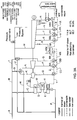
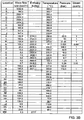
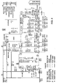
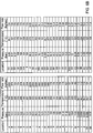
- the power plant as described above in which the conditions thereof are in accordance with example values provided in Fig. 3A with reference to the table in Fig. 3B , as well as in Fig. 4 , can be designed to have a theoretical Rankine efficiency of up to or more than 42%, such as 42.3% in the present example, while having a relatively low operating temperature of below about 400°C, which is a typical operating temperature for a steam-electric power plant which uses solar tube-radiation absorbers as a heat source.
- a reference solar power plant which is designed as per this embodiment, but modified to operate optimally with only one re-heat (i.e., two turbines), yields a lower Rankine efficiency, e.g., about 38.4%.
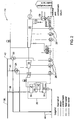
- a second embodiment of the present invention is illustrated in Fig. 5 and comprises all the elements and features of the first embodiment described above, mutatis mutandis , with the main difference that in the second embodiment there are independent solar collection system 12a, 12b, 12c rather than the single solar collection system of the first embodiment.
- each of the heat exchange systems 22, 24, 26 may receive thermal fluid from an independent solar collection system 12a, 12b, 12c, respectively.
- the tube radiation absorbers of the solar collection systems 12a, 12b, 12c are thus in fluid isolation from one another. However, they may be located physically near each one another.
- the second embodiment it is also possible to provide heat to each of the heat exchangers 22, 24, 26, at the same high temperature T max , and thus may require less mass flow of heated thermal liquid to provide the required heat transfer for each heat exchanger. Accordingly, the required infrastructure for providing the heat to the heat exchangers may be simpler and require less pumping power than in the first embodiment.
- the second embodiment may also comprise other features and/or advantages. For example, if one of the solar collection systems 12a, 12b, 12c, needs to be shut down, for example due to malfunction or maintenance, it may be possible for the associated turbine to be shut down, and to provide a bypass flow channel to channel the working fluid between the two remaining turbine, and thus permit operation of the plant 10 using these two turbines, albeit at a lower efficiency. Since there are no fuel related running costs for the solar collection systems, it may still be worthwhile to run the plant at the lower efficiency temporarily.
- any two or all of the solar collection systems 12a, 12b, 12c may be interconnected by means of suitable conduits and valves to enable the same to be in selective fluid communication when desired, in any desired combination, and thus enable thermal fluid to be exchanged between them so that they may operate effectively in a similar manner to the solar collection system of the first embodiment, mutatis mutandis, for example.
- such a configuration may enable thermal fluid from two of the solar collection systems 12a, 12b, 12c, to also provide heat to the other turbine when its associated solar collection system is switched off.
- FIG. 6A Another example of a the solar thermal power plant 10 described above, will be given below is illustrated in Fig. 6A , with values of the states of the working fluid and thermal fluid at various locations therewithin the plant being presented in the table in Fig. 6B .
- the efficiency of the system can be calculated in a known way using these values. In order to reach these values, it was assumed that the steam turbines act reasonably close to an isentropic manner. In addition, condenser pressures, electro-mechanical losses in the generator, pressure loss in piping, temperature differences in heat exchangers, and pumps efficiencies were assumed to be consistent with those generally obtained in practiced.
- a gross efficiency of substantially 42.51% may be achieved, with a net efficiency of substantially 36.56%.
- a similar system using only one reheat may achieve a gross efficiency of substantially 39.79% and a net efficiency of substantially 35.08%.
- increases in gross and net efficiencies of approximately 6.8% and 4.2%, respectively, may be realized.
Landscapes
- Engineering & Computer Science (AREA)
- Chemical & Material Sciences (AREA)
- Combustion & Propulsion (AREA)
- Mechanical Engineering (AREA)
- General Engineering & Computer Science (AREA)
- Life Sciences & Earth Sciences (AREA)
- Sustainable Development (AREA)
- Sustainable Energy (AREA)
- Physics & Mathematics (AREA)
- Thermal Sciences (AREA)
- Engine Equipment That Uses Special Cycles (AREA)
Claims (15)
- Centrale héliothermique (10) comprenant un système collecteur d'énergie solaire (12) et une centrale thermique à vapeur (14), dans laquelle :(a) ledit système collecteur d'énergie solaire comprend un ou plusieurs tube(s) absorbeur(s) de rayonnement (15) contenant un fluide thermique dans celui-ci/ceux-ci, ledit système étant configuré pour chauffer ledit fluide thermique en faisant passer le fluide thermique à travers ledit/lesdits tube(s) absorbeur(s) de rayonnement tandis que lesdits absorbeurs sont irradiés avec un rayonnement solaire ; et dans laquelle(b) ladite centrale thermique à vapeur comprend une turbine à vapeur à pression intermédiaire (18), une turbine à vapeur basse pression (20), au moins une turbine à vapeur additionnelle (16) ayant une pression d'entrée supérieure à celle de la turbine à vapeur à pression intermédiaire, et des canalisations contenant un fluide de travail ; chaque turbine étant associée avec un système d'échange de chaleur adapté à transférer une chaleur dudit fluide thermique audit fluide de travail,caractérisée en ce que le système d'échange de chaleur associé avec ladite turbine à vapeur additionnelle comprend trois échangeurs de chaleur (22, 24, 26), un premier étant un système de préchauffage (30), un deuxième étant un évaporateur (32), et un troisième étant un surchauffeur (34).
- Centrale héliothermique selon la revendication 1, dans laquelle ledit fluide thermique est choisi parmi le groupe comprenant des huiles thermiques et de la vapeur/de l'eau.
- Centrale héliothermique selon la revendication 1, dans laquelle ledit fluide thermique est choisi parmi le groupe comprenant des sels fondus, le dioxyde de carbone, et l'hélium.
- Centrale héliothermique selon l'une quelconque des revendications 1 à 3, dans laquelle ledit système collecteur d'énergie solaire comprend en outre des miroirs cylindro-paraboliques.
- Centrale héliothermique selon la revendication 4, dans laquelle lesdits miroirs cylindro-paraboliques sont des réflecteurs paraboliques à suivi du soleil à axe unique.
- Centrale héliothermique selon la revendication 4, dans laquelle lesdits miroirs cylindro-paraboliques sont des capteurs à lentille de Fresnel linéaires.
- Centrale héliothermique selon l'une quelconque des revendications 1 à 4, dans laquelle ledit fluide thermique est amené jusqu'à chaque dit système d'échange de chaleur à sensiblement la même température opérationnelle 25.
- Centrale héliothermique selon l'une quelconque des revendications précédentes, dans laquelle ledit fluide thermique est de l'eau/de la vapeur.
- Centrale héliothermique selon l'une quelconque des revendications précédentes, ladite centrale héliothermique ayant une température opérationnelle inférieure à environ 400°C.
- Centrale héliothermique selon l'une quelconque des revendications précédentes, comprenant une dite turbine additionnelle, dans laquelle les pressions d'entrée de ladite turbine additionnelle, de ladite turbine à pression intermédiaire et de ladite turbine basse pression sont environ 150 bars, 60 bars, et 20 bars respectivement.
- Centrale héliothermique selon l'une quelconque des revendications précédentes, ayant un rendement brut du cycle de Rankine d'au moins sensiblement 42%.
- Centrale héliothermique selon l'une quelconque des revendications précédentes, comprenant en outre un contrôleur adapté à commander une distribution du fluide thermique à chacun des systèmes d'échange de chaleur de telle manière que le rendement de la centrale est optimisé.
- Centrale héliothermique selon l'une quelconque des revendications précédentes, où lesdits tubes absorbeurs de rayonnement sont disposés à l'intérieur de tubes transparents sous vide, au moins à l'intérieur du système collecteur d'énergie solaire.
- Centrale héliothermique selon l'une quelconque des revendications précédentes, dans laquelle le système d'échange de chaleur associé avec la turbine à pression intermédiaire constitue un premier réchauffeur, et le système d'échange de chaleur associé avec la turbine basse pression constitue un deuxième réchauffeur.
- Procédé de génération d'énergie en utilisant une centrale héliothermique selon l'une quelconque des revendications 1 à 14 comprenant :(a) l'extraction d'énergie d'un fluide de travail par expansion dudit fluide de travail en série dans au moins trois étages de turbine, dans lequel, avant chacun desdits étages d'expansion, le fluide de travail est chauffé à une température prédéterminée associée avec l'étage correspondant ; et(b) la conversion de ladite énergie extraite en énergie électrique ;dans lequel ledit fluide de travail est chauffé au moyen d'un transfert de chaleur depuis un fluide thermique, et dans lequel ledit fluide thermique est chauffé au préalable en faisant passer le fluide thermique à travers un ou plusieurs tube(s) absorbeur(s) de rayonnement tandis que lesdits absorbeurs sont irradiés avec un rayonnement solaire.
Applications Claiming Priority (2)
| Application Number | Priority Date | Filing Date | Title |
|---|---|---|---|
| US96001607P | 2007-09-11 | 2007-09-11 | |
| PCT/IL2008/001220 WO2009034577A2 (fr) | 2007-09-11 | 2008-09-11 | Centrale thermodynamique |
Publications (3)
| Publication Number | Publication Date |
|---|---|
| EP2195532A2 EP2195532A2 (fr) | 2010-06-16 |
| EP2195532B1 true EP2195532B1 (fr) | 2016-11-02 |
| EP2195532B8 EP2195532B8 (fr) | 2016-12-21 |
Family
ID=40416945
Family Applications (1)
| Application Number | Title | Priority Date | Filing Date |
|---|---|---|---|
| EP08808023.9A Not-in-force EP2195532B8 (fr) | 2007-09-11 | 2008-09-11 | Centrale thermodynamique |
Country Status (7)
| Country | Link |
|---|---|
| US (1) | US8572968B2 (fr) |
| EP (1) | EP2195532B8 (fr) |
| CN (1) | CN101821502B (fr) |
| AU (1) | AU2008299321B2 (fr) |
| ES (1) | ES2608490T3 (fr) |
| WO (1) | WO2009034577A2 (fr) |
| ZA (1) | ZA201000863B (fr) |
Families Citing this family (49)
| Publication number | Priority date | Publication date | Assignee | Title |
|---|---|---|---|---|
| US20090125152A1 (en) * | 2007-11-09 | 2009-05-14 | Markron Technologies, Llc | Method of measurement, control, and regulation for the solar thermal hybridization of a fossil fired rankine cycle |
| EP2329144A2 (fr) | 2008-09-17 | 2011-06-08 | Siemens Concentrated Solar Power Ltd. | Centrale thermique solaire |
| CN102292539B (zh) | 2008-12-29 | 2015-06-17 | 西门子聚集太阳能有限公司 | 太阳能热电厂中用于运送传热流体的管道 |
| US10047637B2 (en) | 2009-03-26 | 2018-08-14 | Terrajoule Corporation | Intermediate pressure storage system for thermal storage |
| DE102009056707A1 (de) * | 2009-04-18 | 2010-10-21 | Alstom Technology Ltd. | Dampfkraftwerk mit Solarkollektoren |
| PT2427700T (pt) | 2009-05-07 | 2019-05-21 | Siemens Concentrated Solar Power Ltd | Estrutura de suporte de getter para central solar térmica |
| AU2010313242A1 (en) * | 2009-10-30 | 2012-05-24 | Areva Solar, Inc. | Dual fluid circuit system for generating a vaporous working fluid using solar energy |
| WO2011146093A2 (fr) | 2009-12-15 | 2011-11-24 | William Marsh Rice University | Production d'électricité |
| CN102822521B (zh) * | 2010-03-30 | 2016-01-27 | 西门子公司 | 具有间接蒸发的太阳能热发电站和运行这种太阳能热发电站的方法 |
| JP5597016B2 (ja) * | 2010-04-07 | 2014-10-01 | 株式会社東芝 | 蒸気タービンプラント |
| JP5479192B2 (ja) * | 2010-04-07 | 2014-04-23 | 株式会社東芝 | 蒸気タービンプラント |
| JP5479191B2 (ja) | 2010-04-07 | 2014-04-23 | 株式会社東芝 | 蒸気タービンプラント |
| GB201006497D0 (en) | 2010-04-19 | 2010-06-02 | Dow Corning | Solar thermal power plant |
| DE102010027226A1 (de) * | 2010-05-06 | 2011-11-10 | Siemens Aktiengesellschaft | Solarer Kraftwerksteil einer solarthermischen Kraftwerksanlage und solarthermische Kraftwerksanlage mit Sonnenkollektorflächen für Wärmeträgermedium und Arbeismedium |
| CN103477033A (zh) | 2010-09-30 | 2013-12-25 | 陶氏环球技术有限责任公司 | 用于从聚光太阳能设备产生过热蒸汽的方法和设备 |
| CN102454440B (zh) * | 2010-10-20 | 2015-04-22 | 中国科学院工程热物理研究所 | 板槽结合的太阳能与火电站互补发电系统 |
| CN102454563B (zh) * | 2010-10-20 | 2013-09-11 | 中国科学院工程热物理研究所 | 注蒸汽式的太阳能与火电站互补发电系统 |
| US20120102950A1 (en) * | 2010-11-02 | 2012-05-03 | Alliance For Sustainable Energy, Llc. | Solar thermal power plant with the integration of an aeroderivative turbine |
| BR112013014210B1 (pt) | 2010-12-10 | 2019-12-10 | Angus Chemical | processo para usar um nitroalcano como arrastador |
| WO2012082364A1 (fr) * | 2010-12-15 | 2012-06-21 | William Marsh Rice University | Distillation d'un mélange chimique utilisant un complexe absorbant un rayonnement électromagnétique pour le chauffage |
| US9863662B2 (en) | 2010-12-15 | 2018-01-09 | William Marsh Rice University | Generating a heated fluid using an electromagnetic radiation-absorbing complex |
| US9222665B2 (en) | 2010-12-15 | 2015-12-29 | William Marsh Rice University | Waste remediation |
| WO2012082368A1 (fr) * | 2010-12-15 | 2012-06-21 | William Marsh Rice University | Purification de fluide à l'aide d'un caloporteur comportant un complexe absorbant un rayonnement électromagnétique |
| WO2012107811A2 (fr) * | 2011-02-08 | 2012-08-16 | Brightsource Industries (Israel) Ltd. | Système de stockage d'énergie solaire comportant trois réservoirs ou plus |
| WO2012128715A1 (fr) | 2011-03-22 | 2012-09-27 | Climeon Ab | Procédé permettant de convertir une chaleur à basse température en électricité et refroidissement et son système |
| GB201104975D0 (en) | 2011-03-24 | 2011-05-11 | Dow Corning | Generation of vapour for use in an industrial process |
| DE102011007370A1 (de) * | 2011-04-14 | 2012-10-18 | Siemens Aktiengesellschaft | Solarthermisches Kraftwerk mit Speicher für ein Wärmeträgermedium und Verfahren zum Betreiben des solarthermischen Kraftwerks im Entlademodus des Speichers |
| EP2546521A1 (fr) * | 2011-07-15 | 2013-01-16 | Siemens Aktiengesellschaft | Préchauffage surérogatoire à basse pression pour le réglage en fréquence ou secondaire et/ou primaire, d'une centrale thermo-solaire |
| US20140352304A1 (en) * | 2011-08-30 | 2014-12-04 | Abengoa Solor LLC | Hybrid solar field |
| US9038387B2 (en) | 2011-08-31 | 2015-05-26 | Brightsource Industries (Israel) Ltd | Solar thermal electricity generating systems with thermal storage |
| US20130111902A1 (en) * | 2011-11-03 | 2013-05-09 | Mansour Maleki-Ardebili | Solar power system and method of operating a solar power system |
| EP2610489A1 (fr) | 2011-12-30 | 2013-07-03 | Alstom Technology Ltd | Central thermique avec un récepteur solaire integré |
| DE102012204218A1 (de) * | 2012-03-16 | 2013-09-19 | Siemens Aktiengesellschaft | Leistungsregelung und/oder Frequenzregelung bei einem solarthermischen Dampfkraftwerk |
| DE102012206466A1 (de) * | 2012-04-19 | 2013-10-24 | Siemens Aktiengesellschaft | Verfahren und Vorrichtung zum Betrieb eines solarthermischen Kraftwerks |
| CN103375369B (zh) * | 2012-04-28 | 2017-02-08 | 杭州三花研究院有限公司 | 一种太阳能辅助燃煤电站发电系统 |
| EP2861908B1 (fr) * | 2012-05-10 | 2020-12-23 | Stamicarbon B.V. acting under the name of MT Innovation Center | Procédé de modification d'une centrale thermique solaire fonctionnant sur une technologie à base d'huile classique dans une centrale thermique solaire hybride et une telle installation d'énergie thermique solaire hybride |
| EP2667028A1 (fr) * | 2012-05-25 | 2013-11-27 | Alstom Technology Ltd | Installation solaire à cycle de Rankine à vapeur et procédé de fonctionnement de telles installations |
| US9541071B2 (en) | 2012-12-04 | 2017-01-10 | Brightsource Industries (Israel) Ltd. | Concentrated solar power plant with independent superheater |
| US20150082791A1 (en) * | 2013-09-26 | 2015-03-26 | General Electric Company | Steam turbine system with steam turbine clutch |
| EP3055562B1 (fr) * | 2013-10-08 | 2018-03-21 | KT - Kinetics Technology S.p.A. | Procédé de chauffage contrôlé d'un fluide de traitement par le biais d'une centrale solaire thermique à concentration et d'un système caloporteur et appareil associé |
| CN103727687B (zh) * | 2013-12-30 | 2016-01-13 | 北京工业大学 | 一种双熔盐太阳能热发电传热蓄热系统 |
| SE1400492A1 (sv) | 2014-01-22 | 2015-07-23 | Climeon Ab | An improved thermodynamic cycle operating at low pressure using a radial turbine |
| ES2846148T3 (es) * | 2015-04-21 | 2021-07-28 | General Electric Technology Gmbh | Generador de vapor de un solo paso de sal fundida |
| US9845998B2 (en) | 2016-02-03 | 2017-12-19 | Sten Kreuger | Thermal energy storage and retrieval systems |
| CN107023446B (zh) * | 2017-06-22 | 2019-02-15 | 哈尔滨锅炉厂有限责任公司 | 一种以二氧化碳为储热及做功工质的菲涅尔式太阳能光热发电系统 |
| CN107023447A (zh) * | 2017-06-22 | 2017-08-08 | 哈尔滨锅炉厂有限责任公司 | 以二氧化碳为集热工质的槽式太阳能光热发电系统 |
| CN108223318B (zh) * | 2018-01-31 | 2023-10-27 | 华南理工大学 | 一种基于联合储能的三压三热太阳能热发电系统 |
| US11852044B2 (en) | 2019-08-08 | 2023-12-26 | Bayram ARI | Power generating machine system |
| IL284495A (en) * | 2021-06-28 | 2023-01-01 | Tzion Tzabari | Novel solar thermal panel unit |
Family Cites Families (20)
| Publication number | Priority date | Publication date | Assignee | Title |
|---|---|---|---|---|
| US3951129A (en) * | 1974-10-29 | 1976-04-20 | The United States Of America As Represented By The United States National Aeronautics And Space Administration | Solar energy absorber |
| JPS51129947A (en) * | 1975-04-21 | 1976-11-11 | British Petroleum Co | Solar energy collecting apparatus |
| US4072182A (en) * | 1977-01-05 | 1978-02-07 | International Power Technology, Inc. | Pressure staged heat exchanger |
| FR2450363A1 (fr) * | 1979-02-28 | 1980-09-26 | Anvar | Centrale thermique de production d'electricite a partir d'energie solaire |
| JPH0718525B2 (ja) * | 1987-05-06 | 1995-03-06 | 株式会社日立製作所 | 排ガスボイラ |
| DE3741882C1 (en) * | 1987-12-10 | 1989-02-02 | Gea Luftkuehler Happel Gmbh | Steam generator with once-through forced flow |
| US5182912A (en) * | 1991-03-12 | 1993-02-02 | Solar Reactor Technologies, Inc. | Fluid absorption receiver for solar radiation |
| DE4126037A1 (de) * | 1991-08-06 | 1993-02-11 | Siemens Ag | Gas- und dampfturbinenkraftwerk mit einem solar beheizten dampferzeuger |
| DE4303613C2 (de) * | 1993-02-09 | 1998-12-17 | Steinmueller Gmbh L & C | Verfahren zur Erzeugung von Dampf in einem Zwangsdurchlaufdampferzeuger |
| DE19651645C2 (de) | 1996-12-12 | 2002-10-24 | Deutsch Zentr Luft & Raumfahrt | Verfahren zur Nutzung von Solarenergie in einem Gas- und Dampf-Kraftwerk und Gas- und Dampf-Kraftwerk |
| DE19652349C2 (de) | 1996-12-17 | 1999-04-22 | Reinhard Prof Dr Tech Leithner | Solar- und Niedertemperaturwärme-Kombianlage-Solico |
| RU2193726C2 (ru) * | 1997-06-30 | 2002-11-27 | Сименс Акциенгезелльшафт | Парогенератор, работающий на отходящем тепле |
| US6422017B1 (en) * | 1998-09-03 | 2002-07-23 | Ashraf Maurice Bassily | Reheat regenerative rankine cycle |
| US6223743B1 (en) * | 1999-05-18 | 2001-05-01 | Melvin L. Prueitt | Solar power generation and energy storage system |
| JP3780884B2 (ja) * | 2001-08-31 | 2006-05-31 | 株式会社日立製作所 | 蒸気タービン発電プラント |
| US20070157614A1 (en) * | 2003-01-21 | 2007-07-12 | Goldman Arnold J | Hybrid Generation with Alternative Fuel Sources |
| AU2003903767A0 (en) * | 2003-07-21 | 2003-08-07 | Steven Kenessey | Eco tower |
| US7296410B2 (en) * | 2003-12-10 | 2007-11-20 | United Technologies Corporation | Solar power system and method for power generation |
| US7171812B2 (en) * | 2004-03-15 | 2007-02-06 | Powerstreams, Inc. | Electric generation facility and method employing solar technology |
| CN1940254B (zh) * | 2005-09-29 | 2014-04-16 | 罗桂荣 | 动力循环系统与制冷循环系统复合式热力发动机 |
-
2008
- 2008-09-11 ES ES08808023.9T patent/ES2608490T3/es active Active
- 2008-09-11 WO PCT/IL2008/001220 patent/WO2009034577A2/fr not_active Ceased
- 2008-09-11 EP EP08808023.9A patent/EP2195532B8/fr not_active Not-in-force
- 2008-09-11 CN CN200880105751.2A patent/CN101821502B/zh not_active Expired - Fee Related
- 2008-09-11 AU AU2008299321A patent/AU2008299321B2/en not_active Ceased
- 2008-09-11 US US12/733,590 patent/US8572968B2/en not_active Expired - Fee Related
-
2010
- 2010-02-05 ZA ZA2010/00863A patent/ZA201000863B/en unknown
Also Published As
| Publication number | Publication date |
|---|---|
| EP2195532A2 (fr) | 2010-06-16 |
| AU2008299321A1 (en) | 2009-03-19 |
| US8572968B2 (en) | 2013-11-05 |
| WO2009034577A3 (fr) | 2009-05-07 |
| WO2009034577A2 (fr) | 2009-03-19 |
| US20100212318A1 (en) | 2010-08-26 |
| AU2008299321B2 (en) | 2013-10-24 |
| CN101821502A (zh) | 2010-09-01 |
| CN101821502B (zh) | 2014-12-17 |
| ES2608490T3 (es) | 2017-04-11 |
| ZA201000863B (en) | 2011-11-30 |
| EP2195532B8 (fr) | 2016-12-21 |
Similar Documents
| Publication | Publication Date | Title |
|---|---|---|
| US8572968B2 (en) | Solar thermal power plants | |
| US8544273B2 (en) | Solar thermal power plant | |
| AU2009312347B2 (en) | Solar thermal power plant and dual-purpose pipe for use therewith | |
| AU2010326107B2 (en) | Utilizing steam and/or hot water generated using solar energy | |
| US9255569B2 (en) | Systems, methods, and devices for operating a solar thermal electricity generating system | |
| CN102405349B (zh) | 具有太阳能收集器的蒸汽发电厂 | |
| AU2008228211B2 (en) | Method and device for intermediate superheating in solar direct evaporation in a solar-thermal power plant | |
| US20080092551A1 (en) | Method and system integrating combustion turbine with a regenerative solar rankine power plant | |
| CN103375369B (zh) | 一种太阳能辅助燃煤电站发电系统 | |
| EP2382669A1 (fr) | Systèmes d'énergie à cycles combinés solaires | |
| CN102753823A (zh) | 用于利用太阳能产生蒸气状工作流体的双流体线路系统 | |
| US20130111902A1 (en) | Solar power system and method of operating a solar power system | |
| US20150167647A1 (en) | Concentrating solar power plant with hybrid collector field | |
| CN102859190A (zh) | 太阳能热力发电设备 | |
| EP2834476A1 (fr) | Système de chaudière de secours pour une centrale héliothermique utilisant la technologie des sels fondus, une centrale héliothermique et un procédé pour faire fonctionner une centrale héliothermique | |
| US20140060053A1 (en) | Steam power plant and method of operating a steam power plant | |
| US20130312413A1 (en) | Steam rankine cycle solar plant and method for operating such plants | |
| CN105247208B (zh) | 具有蓄热器的太阳能集热器厂 | |
| WO2017078134A1 (fr) | Système de collecte de chaleur solaire et son procédé de fonctionnement |
Legal Events
| Date | Code | Title | Description |
|---|---|---|---|
| PUAI | Public reference made under article 153(3) epc to a published international application that has entered the european phase |
Free format text: ORIGINAL CODE: 0009012 |
|
| 17P | Request for examination filed |
Effective date: 20100326 |
|
| AK | Designated contracting states |
Kind code of ref document: A2 Designated state(s): AT BE BG CH CY CZ DE DK EE ES FI FR GB GR HR HU IE IS IT LI LT LU LV MC MT NL NO PL PT RO SE SI SK TR |
|
| AX | Request for extension of the european patent |
Extension state: AL BA MK RS |
|
| DAX | Request for extension of the european patent (deleted) | ||
| 17Q | First examination report despatched |
Effective date: 20150602 |
|
| GRAP | Despatch of communication of intention to grant a patent |
Free format text: ORIGINAL CODE: EPIDOSNIGR1 |
|
| INTG | Intention to grant announced |
Effective date: 20160419 |
|
| GRAS | Grant fee paid |
Free format text: ORIGINAL CODE: EPIDOSNIGR3 |
|
| GRAA | (expected) grant |
Free format text: ORIGINAL CODE: 0009210 |
|
| AK | Designated contracting states |
Kind code of ref document: B1 Designated state(s): AT BE BG CH CY CZ DE DK EE ES FI FR GB GR HR HU IE IS IT LI LT LU LV MC MT NL NO PL PT RO SE SI SK TR |
|
| REG | Reference to a national code |
Ref country code: GB Ref legal event code: FG4D |
|
| REG | Reference to a national code |
Ref country code: DE Ref legal event code: R081 Ref document number: 602008047191 Country of ref document: DE Owner name: SIEMENS CONCENTRATED SOLAR POWER LTD., IL Free format text: FORMER OWNER: SIEMENS CONCENTRATED SOLAR POWER LTD., BEIT SHEMESH, IL |
|
| REG | Reference to a national code |
Ref country code: AT Ref legal event code: REF Ref document number: 842129 Country of ref document: AT Kind code of ref document: T Effective date: 20161115 Ref country code: CH Ref legal event code: EP |
|
| RAP2 | Party data changed (patent owner data changed or rights of a patent transferred) |
Owner name: SIEMENS CONCENTRATED SOLAR POWER LTD. |
|
| REG | Reference to a national code |
Ref country code: IE Ref legal event code: FG4D |
|
| REG | Reference to a national code |
Ref country code: DE Ref legal event code: R096 Ref document number: 602008047191 Country of ref document: DE |
|
| PG25 | Lapsed in a contracting state [announced via postgrant information from national office to epo] |
Ref country code: LV Free format text: LAPSE BECAUSE OF FAILURE TO SUBMIT A TRANSLATION OF THE DESCRIPTION OR TO PAY THE FEE WITHIN THE PRESCRIBED TIME-LIMIT Effective date: 20161102 |
|
| REG | Reference to a national code |
Ref country code: NL Ref legal event code: MP Effective date: 20161102 |
|
| REG | Reference to a national code |
Ref country code: LT Ref legal event code: MG4D |
|
| REG | Reference to a national code |
Ref country code: AT Ref legal event code: MK05 Ref document number: 842129 Country of ref document: AT Kind code of ref document: T Effective date: 20161102 |
|
| REG | Reference to a national code |
Ref country code: ES Ref legal event code: FG2A Ref document number: 2608490 Country of ref document: ES Kind code of ref document: T3 Effective date: 20170411 |
|
| PG25 | Lapsed in a contracting state [announced via postgrant information from national office to epo] |
Ref country code: NL Free format text: LAPSE BECAUSE OF FAILURE TO SUBMIT A TRANSLATION OF THE DESCRIPTION OR TO PAY THE FEE WITHIN THE PRESCRIBED TIME-LIMIT Effective date: 20161102 Ref country code: GR Free format text: LAPSE BECAUSE OF FAILURE TO SUBMIT A TRANSLATION OF THE DESCRIPTION OR TO PAY THE FEE WITHIN THE PRESCRIBED TIME-LIMIT Effective date: 20170203 Ref country code: NO Free format text: LAPSE BECAUSE OF FAILURE TO SUBMIT A TRANSLATION OF THE DESCRIPTION OR TO PAY THE FEE WITHIN THE PRESCRIBED TIME-LIMIT Effective date: 20170202 Ref country code: LT Free format text: LAPSE BECAUSE OF FAILURE TO SUBMIT A TRANSLATION OF THE DESCRIPTION OR TO PAY THE FEE WITHIN THE PRESCRIBED TIME-LIMIT Effective date: 20161102 Ref country code: SE Free format text: LAPSE BECAUSE OF FAILURE TO SUBMIT A TRANSLATION OF THE DESCRIPTION OR TO PAY THE FEE WITHIN THE PRESCRIBED TIME-LIMIT Effective date: 20161102 |
|
| PG25 | Lapsed in a contracting state [announced via postgrant information from national office to epo] |
Ref country code: FI Free format text: LAPSE BECAUSE OF FAILURE TO SUBMIT A TRANSLATION OF THE DESCRIPTION OR TO PAY THE FEE WITHIN THE PRESCRIBED TIME-LIMIT Effective date: 20161102 Ref country code: AT Free format text: LAPSE BECAUSE OF FAILURE TO SUBMIT A TRANSLATION OF THE DESCRIPTION OR TO PAY THE FEE WITHIN THE PRESCRIBED TIME-LIMIT Effective date: 20161102 Ref country code: PT Free format text: LAPSE BECAUSE OF FAILURE TO SUBMIT A TRANSLATION OF THE DESCRIPTION OR TO PAY THE FEE WITHIN THE PRESCRIBED TIME-LIMIT Effective date: 20170302 Ref country code: IS Free format text: LAPSE BECAUSE OF FAILURE TO SUBMIT A TRANSLATION OF THE DESCRIPTION OR TO PAY THE FEE WITHIN THE PRESCRIBED TIME-LIMIT Effective date: 20170302 Ref country code: PL Free format text: LAPSE BECAUSE OF FAILURE TO SUBMIT A TRANSLATION OF THE DESCRIPTION OR TO PAY THE FEE WITHIN THE PRESCRIBED TIME-LIMIT Effective date: 20161102 Ref country code: HR Free format text: LAPSE BECAUSE OF FAILURE TO SUBMIT A TRANSLATION OF THE DESCRIPTION OR TO PAY THE FEE WITHIN THE PRESCRIBED TIME-LIMIT Effective date: 20161102 |
|
| PG25 | Lapsed in a contracting state [announced via postgrant information from national office to epo] |
Ref country code: CZ Free format text: LAPSE BECAUSE OF FAILURE TO SUBMIT A TRANSLATION OF THE DESCRIPTION OR TO PAY THE FEE WITHIN THE PRESCRIBED TIME-LIMIT Effective date: 20161102 Ref country code: RO Free format text: LAPSE BECAUSE OF FAILURE TO SUBMIT A TRANSLATION OF THE DESCRIPTION OR TO PAY THE FEE WITHIN THE PRESCRIBED TIME-LIMIT Effective date: 20161102 Ref country code: DK Free format text: LAPSE BECAUSE OF FAILURE TO SUBMIT A TRANSLATION OF THE DESCRIPTION OR TO PAY THE FEE WITHIN THE PRESCRIBED TIME-LIMIT Effective date: 20161102 Ref country code: EE Free format text: LAPSE BECAUSE OF FAILURE TO SUBMIT A TRANSLATION OF THE DESCRIPTION OR TO PAY THE FEE WITHIN THE PRESCRIBED TIME-LIMIT Effective date: 20161102 Ref country code: SK Free format text: LAPSE BECAUSE OF FAILURE TO SUBMIT A TRANSLATION OF THE DESCRIPTION OR TO PAY THE FEE WITHIN THE PRESCRIBED TIME-LIMIT Effective date: 20161102 |
|
| REG | Reference to a national code |
Ref country code: DE Ref legal event code: R097 Ref document number: 602008047191 Country of ref document: DE |
|
| PG25 | Lapsed in a contracting state [announced via postgrant information from national office to epo] |
Ref country code: BE Free format text: LAPSE BECAUSE OF FAILURE TO SUBMIT A TRANSLATION OF THE DESCRIPTION OR TO PAY THE FEE WITHIN THE PRESCRIBED TIME-LIMIT Effective date: 20161102 Ref country code: BG Free format text: LAPSE BECAUSE OF FAILURE TO SUBMIT A TRANSLATION OF THE DESCRIPTION OR TO PAY THE FEE WITHIN THE PRESCRIBED TIME-LIMIT Effective date: 20170202 |
|
| PLBE | No opposition filed within time limit |
Free format text: ORIGINAL CODE: 0009261 |
|
| STAA | Information on the status of an ep patent application or granted ep patent |
Free format text: STATUS: NO OPPOSITION FILED WITHIN TIME LIMIT |
|
| 26N | No opposition filed |
Effective date: 20170803 |
|
| PG25 | Lapsed in a contracting state [announced via postgrant information from national office to epo] |
Ref country code: SI Free format text: LAPSE BECAUSE OF FAILURE TO SUBMIT A TRANSLATION OF THE DESCRIPTION OR TO PAY THE FEE WITHIN THE PRESCRIBED TIME-LIMIT Effective date: 20161102 |
|
| REG | Reference to a national code |
Ref country code: DE Ref legal event code: R119 Ref document number: 602008047191 Country of ref document: DE |
|
| REG | Reference to a national code |
Ref country code: CH Ref legal event code: PL |
|
| GBPC | Gb: european patent ceased through non-payment of renewal fee |
Effective date: 20170911 |
|
| PG25 | Lapsed in a contracting state [announced via postgrant information from national office to epo] |
Ref country code: MC Free format text: LAPSE BECAUSE OF FAILURE TO SUBMIT A TRANSLATION OF THE DESCRIPTION OR TO PAY THE FEE WITHIN THE PRESCRIBED TIME-LIMIT Effective date: 20161102 |
|
| REG | Reference to a national code |
Ref country code: IE Ref legal event code: MM4A |
|
| PG25 | Lapsed in a contracting state [announced via postgrant information from national office to epo] |
Ref country code: LU Free format text: LAPSE BECAUSE OF NON-PAYMENT OF DUE FEES Effective date: 20170911 |
|
| REG | Reference to a national code |
Ref country code: FR Ref legal event code: ST Effective date: 20180531 |
|
| PG25 | Lapsed in a contracting state [announced via postgrant information from national office to epo] |
Ref country code: LI Free format text: LAPSE BECAUSE OF NON-PAYMENT OF DUE FEES Effective date: 20170930 Ref country code: CH Free format text: LAPSE BECAUSE OF NON-PAYMENT OF DUE FEES Effective date: 20170930 Ref country code: DE Free format text: LAPSE BECAUSE OF NON-PAYMENT OF DUE FEES Effective date: 20180404 Ref country code: IE Free format text: LAPSE BECAUSE OF NON-PAYMENT OF DUE FEES Effective date: 20170911 Ref country code: GB Free format text: LAPSE BECAUSE OF NON-PAYMENT OF DUE FEES Effective date: 20170911 |
|
| PG25 | Lapsed in a contracting state [announced via postgrant information from national office to epo] |
Ref country code: FR Free format text: LAPSE BECAUSE OF NON-PAYMENT OF DUE FEES Effective date: 20171002 Ref country code: IT Free format text: LAPSE BECAUSE OF NON-PAYMENT OF DUE FEES Effective date: 20170911 |
|
| PG25 | Lapsed in a contracting state [announced via postgrant information from national office to epo] |
Ref country code: MT Free format text: LAPSE BECAUSE OF NON-PAYMENT OF DUE FEES Effective date: 20170911 |
|
| REG | Reference to a national code |
Ref country code: ES Ref legal event code: FD2A Effective date: 20181024 |
|
| PG25 | Lapsed in a contracting state [announced via postgrant information from national office to epo] |
Ref country code: ES Free format text: LAPSE BECAUSE OF NON-PAYMENT OF DUE FEES Effective date: 20170912 |
|
| PG25 | Lapsed in a contracting state [announced via postgrant information from national office to epo] |
Ref country code: HU Free format text: LAPSE BECAUSE OF FAILURE TO SUBMIT A TRANSLATION OF THE DESCRIPTION OR TO PAY THE FEE WITHIN THE PRESCRIBED TIME-LIMIT; INVALID AB INITIO Effective date: 20080911 |
|
| PG25 | Lapsed in a contracting state [announced via postgrant information from national office to epo] |
Ref country code: CY Free format text: LAPSE BECAUSE OF NON-PAYMENT OF DUE FEES Effective date: 20161102 |
|
| PG25 | Lapsed in a contracting state [announced via postgrant information from national office to epo] |
Ref country code: TR Free format text: LAPSE BECAUSE OF FAILURE TO SUBMIT A TRANSLATION OF THE DESCRIPTION OR TO PAY THE FEE WITHIN THE PRESCRIBED TIME-LIMIT Effective date: 20161102 |