EP2195559B1 - Schaltvorrichtung mit servounterstützungseinrichtung - Google Patents
Schaltvorrichtung mit servounterstützungseinrichtung Download PDFInfo
- Publication number
- EP2195559B1 EP2195559B1 EP08804948.1A EP08804948A EP2195559B1 EP 2195559 B1 EP2195559 B1 EP 2195559B1 EP 08804948 A EP08804948 A EP 08804948A EP 2195559 B1 EP2195559 B1 EP 2195559B1
- Authority
- EP
- European Patent Office
- Prior art keywords
- pin
- power assistance
- assistance device
- hollow shaft
- shifting apparatus
- Prior art date
- Legal status (The legal status is an assumption and is not a legal conclusion. Google has not performed a legal analysis and makes no representation as to the accuracy of the status listed.)
- Not-in-force
Links
- 230000005540 biological transmission Effects 0.000 claims description 27
- 238000006073 displacement reaction Methods 0.000 description 3
- 238000010276 construction Methods 0.000 description 2
- 238000009434 installation Methods 0.000 description 2
- 230000004913 activation Effects 0.000 description 1
- 230000007935 neutral effect Effects 0.000 description 1
Images

Classifications
-
- F—MECHANICAL ENGINEERING; LIGHTING; HEATING; WEAPONS; BLASTING
- F16—ENGINEERING ELEMENTS AND UNITS; GENERAL MEASURES FOR PRODUCING AND MAINTAINING EFFECTIVE FUNCTIONING OF MACHINES OR INSTALLATIONS; THERMAL INSULATION IN GENERAL
- F16H—GEARING
- F16H61/00—Control functions within control units of change-speed- or reversing-gearings for conveying rotary motion ; Control of exclusively fluid gearing, friction gearing, gearings with endless flexible members or other particular types of gearing
- F16H61/26—Generation or transmission of movements for final actuating mechanisms
- F16H61/28—Generation or transmission of movements for final actuating mechanisms with at least one movement of the final actuating mechanism being caused by a non-mechanical force, e.g. power-assisted
- F16H61/30—Hydraulic or pneumatic motors or related fluid control means therefor
-
- F—MECHANICAL ENGINEERING; LIGHTING; HEATING; WEAPONS; BLASTING
- F16—ENGINEERING ELEMENTS AND UNITS; GENERAL MEASURES FOR PRODUCING AND MAINTAINING EFFECTIVE FUNCTIONING OF MACHINES OR INSTALLATIONS; THERMAL INSULATION IN GENERAL
- F16H—GEARING
- F16H61/00—Control functions within control units of change-speed- or reversing-gearings for conveying rotary motion ; Control of exclusively fluid gearing, friction gearing, gearings with endless flexible members or other particular types of gearing
- F16H61/26—Generation or transmission of movements for final actuating mechanisms
- F16H61/28—Generation or transmission of movements for final actuating mechanisms with at least one movement of the final actuating mechanism being caused by a non-mechanical force, e.g. power-assisted
- F16H61/30—Hydraulic or pneumatic motors or related fluid control means therefor
- F16H2061/301—Hydraulic or pneumatic motors or related fluid control means therefor for power assistance, i.e. servos with follow up action
-
- F—MECHANICAL ENGINEERING; LIGHTING; HEATING; WEAPONS; BLASTING
- F16—ENGINEERING ELEMENTS AND UNITS; GENERAL MEASURES FOR PRODUCING AND MAINTAINING EFFECTIVE FUNCTIONING OF MACHINES OR INSTALLATIONS; THERMAL INSULATION IN GENERAL
- F16H—GEARING
- F16H61/00—Control functions within control units of change-speed- or reversing-gearings for conveying rotary motion ; Control of exclusively fluid gearing, friction gearing, gearings with endless flexible members or other particular types of gearing
- F16H61/26—Generation or transmission of movements for final actuating mechanisms
- F16H61/28—Generation or transmission of movements for final actuating mechanisms with at least one movement of the final actuating mechanism being caused by a non-mechanical force, e.g. power-assisted
- F16H61/30—Hydraulic or pneumatic motors or related fluid control means therefor
- F16H2061/301—Hydraulic or pneumatic motors or related fluid control means therefor for power assistance, i.e. servos with follow up action
- F16H2061/302—Hydraulic or pneumatic motors or related fluid control means therefor for power assistance, i.e. servos with follow up action with variable force amplification, e.g. force is depending on selected gear or on actuator force (non-linear amplification)
Definitions
- the invention relates to a switching device with power assistance device according to the closer defined in the preamble of claim 1.
- pneumatic switching aids in dissolved construction consist of a mechanical-pneumatic control part and a separate pneumatic power part.
- a switching aid in dissolved construction is off Loomann; Gear transmission; 2nd Edition; Springer Verlag; 1988; P. 225 known.
- the control part is a mechanically operated control valve, which is actuated by the shift linkage. The transmission of the selection movement during the gear change happens mechanically directly to the transmission. In the transmission of the switching movement, the control valve is actuated and at the same time the manual switching force is transmitted mechanically via a lever to the transmission.
- the manual switching force is additionally supported pneumatically by a pneumatic cylinder. This air cylinder forms as a two-position cylinder with integrated hydraulic damper the pneumatic power unit. A direct proportional representation of the manual switching force is not achieved here.
- the paths between control unit and power unit are long and the installation is space consuming.
- the DE 10 2004 041 543 A1 discloses a shifting device with power assist device for a transmission of a motor vehicle, which comprises a central control shaft whose axial displacement in a selection movement and the rotational movement results in a switching movement.
- a control valve of the power assistance device is activated via pins for transmitting the manual switching force and a lever operatively connected to the pins.
- the pins for transmitting the manual switching force engage in longitudinal grooves in the circumference of the switching shaft and are arranged in the longitudinal grooves such that an axial displacement of the switching shaft is made possible.
- corresponding transverse grooves are provided on the longitudinal grooves.
- a generic switching device with a power assistance device for a transmission of a vehicle which comprises means for switching and selecting a gear stage of a transmission and a control rod of the power assistance device, which acts to be supported a manual shift force.
- Elastic elements are provided in the shifting device to alter or limit the manual shifting force applied to the power assisting device prior to being introduced into the power assisting device.
- the DE 10 2006 006 652 A1 also discloses a shifting apparatus having a power assisting device for a transmission of a vehicle, which comprises means for shifting and selecting a gear stage of a transmission and a control rod of the power assisting device to which a manual shifting force to be assisted acts.
- Spring elements are provided in the shifting device to change the manual shifting force acting on the power assisting device within the power assisting device before and / or during the generation of the power assisting force.
- the present invention has for its object to present an embodiment of a switching device with power assistance device, with which a device for limiting the power assistance force can be optimized.
- the object underlying the invention is achieved by a, including the characterizing features of the main claim having, generic switching device with power assistance device.
- the inventive switching device with power assistance device in particular for transmission of commercial vehicles, comprises a switch housing, means for selecting and switching a gear ratio of the transmission and a transmission point for transmitting the manual shift force to the power assistance device.
- the transfer point for transmitting the manual shift force has a lever which is connected to an element of the power assist device.
- the switching device comprises a device for limiting the power assisting force, which is arranged immediately adjacent to the transmission point for transmitting the manual switching force to the power assistance device and comprises a arranged in the switching shaft pin which engages in at least one groove surrounding the switching shaft hollow shaft, wherein by the in the groove of the hollow shaft engaging pin a limitation of the power assistance force is realized.
- the pin is arranged in the shift shaft such that movement of the shift shaft causes immediate movement of the pin.
- the pin is free of play or arranged with minimal play in the shift shaft.
- the groove in the hollow shaft is designed such that different Vermosemployed between the pin, which is arranged in the switching shaft and engages in the groove of the hollow shaft, and the hollow shaft prevail.
- the torsional backlashes can be designed, for example, such that for each alley or for each gear stage another torsional backlash prevails, whereby a different limitation of the power assisting force for each alley or for each gear ratio can be realized.
- the VerFEemployed at smaller gear ratios are designed to be greater than at higher gear ratios, whereby a larger power assistance force is provided for the smaller gear ratios, as for the larger gear ratios of the transmission.
- the gear stage 3 is here understood by a smaller gear, for example, the gear 2 and a larger gear, for example, the gear 4.
- the hollow shaft in the region of the pin for limiting the power assistance force on a second groove which is offset in the hollow shaft by 180 degrees, that is the first groove opposite, is arranged.
- the pin for limiting the power assisting force is in this case designed and arranged in the switching shaft, that it engages in both the first and in the second groove of the hollow shaft, whereby the load occurring is distributed to the two grooves of the hollow shaft.
- the contact surfaces of the pin for limiting the servo-assisting force and the hollow shaft are designed such that upon contact of the pin with the hollow shaft an optimized surface pressure can be achieved.
- the contact surfaces of pin and hollow shaft are conical to each other.
- the pin is designed to limit the power assistance force in the hollow shaft as a stepped pin, creating two contact points between the pin and the hollow shaft.
- an axial securing of the pin for limiting the power assisting force along its longitudinal axis by the switch housing is realized.
- the pin for limiting the power assisting force can be fixed by at least one securing ring and / or a collar on the pin in the switching shaft.
- the element to which the manual switching force to be assisted acts as a control rod of the servo-assisting device.
- a limitation of the servo-assisting force can be realized by a device for limiting the servo-assisting force for each gear stage or each lane, which is arranged directly next to the transmission point for transmitting the manual shifting force to the servo-assistance device.
- the inventive arrangement the problem of occurring tolerances can be kept correspondingly small, whereby the VerFEemployed between the pin, which is arranged in the shift shaft and engages in the groove of the hollow shaft, and the hollow shaft can be accurately represented and thus the servo-assisting force very precisely on the desired value can be limited.
- the Fig. 1 shows a schematic of a switchgear 2 of a motor vehicle according to the prior art, From a shift lever 4 leads from a shift lever 6 via a lever deflection 8 to a switching device 11 with a pneumatic power assistance device 10.
- the pneumatic Power assistance device 10 has a connecting line 12, which leads to a reservoir 14, from which the pneumatic power assistance device 10 is supplied with compressed air.
- the lever deflection 8 has a first lever 16, which is preferably articulated to the shift rod 6.
- the lever deflection 8 has a second lever 18, which in turn engages in a control rod 20 which is arranged in the pneumatic power assistance device 10.
- a piston rod 22 is provided, in which a lever 24 engages, which is connected via a rotatable switching shaft 26 with a lever 28 in the vehicle transmission 30.
- the lever 28 engages in a shift rail 32 through which gear ratios of the transmission can be switched in a known manner.
- a movement of the lever 24 is transmitted via the switching shaft 26 in a movement of the lever 28, so that the lever 28 can put the shift rail 32 in an axial movement.
- the shift rail 32 preferably assumes three positions, two axial end positions, each corresponding to a switched gear ratio and lying between the end positions center position corresponding to a neutral position of the transmission.
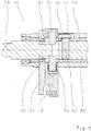
- the Fig. 2 shows the inventive switching device 40 in a sectional view.
- the switching device 40 comprises a central switching shaft 36 which is rotatably mounted within a hollow shaft 38 about its axis 58.
- the switching shaft 36 has at its periphery in the longitudinal direction, ie along the axis 58, longitudinal grooves 50, engage in the pins 34 for transmitting the manual switching force, which in turn are arranged in a lever 18, preferably rotatably mounted in needle bushings.
- the pins 34 are arranged in the grooves 50, that an axial displacement of the switching shaft 36, ie the selection movement is possible, wherein a rotation of the switching shaft 36 about the axis 58 to a pivoting of the lever 18 leads, resulting in an activation of the Servo-assisting device 10 leads, since the lever 18 engages in the control rod 20, not shown here, of the power assistance device 10 (please refer Fig. 1 ).
- the power assisting force generated by the power assisting device 10 is transmitted to the lever 24 from the piston rod 22 (not shown) (see FIG Fig. 1 ).
- the lever 24 is rotatably connected to the hollow shaft 38, whereby the servo-assisting force generated by the power assist device 10 is transmitted via the lever 24 to the hollow shaft 38.
- the hollow shaft 38 is axially fixed in the switching device and arranged rotatably with the switching shaft 36 for switching the shift rails 32.
- the switching device 40 comprises a device for limiting the power assistance force, which is arranged immediately adjacent to the transfer point for transmitting the manual shift force to the power assistance device 10, ie immediately adjacent to the lever 18 in which the pins 34 are arranged, which in the grooves 50 engage the shift shaft 36.
- the device for limiting the power assisting force comprises a pin 42 arranged in the switching shaft 36, which engages here in a groove 46 of the hollow shaft 38.
- the groove 46 in the hollow shaft 38 is in this case designed such that prevail between the groove 46 and the pin 42 and thus between the hollow shaft 38 and the switching shaft 36 corresponding Verwindieri.
- the power assistance force can be limited accordingly for each lane or grade.
- the servo-assisting force limiting pin 42 arranged in the switching shaft 36 is arranged symmetrically with respect to the groove 50 in the switching shaft 36 and thus symmetrically with respect to the pins 34 for transmitting the manual shifting force to the power assisting device 10.
- An axial securing of the pin 42 along its longitudinal axis is realized here by the switch housing 44.
- the shift shaft 36 can be rotatably operated to transmit the manual shift force to the triggering lever 18 of the power assist device 10 and to transmit the manual shift force to the shift rails 32nd Furthermore, the shift shaft 36 can be actuated axially to select the shift rail 32 to be shifted, ie for the selection movement.
- the Fig. 3 shows the switching shaft 36, the hollow shaft 38, which surrounds the switching shaft 36, the groove 46 in the hollow shaft 38, the pin 42 which engages in the groove 46 and is arranged in the switching shaft 36, the lever 24, the rotationally fixed to the hollow shaft 38 is connected and the lever 18, which via pins 34 (see Fig. 2 ) is in communication with the switching shaft 36.
- the pin 42 is indicated in the groove 46 in three different positions, but it is in the groove 46 only once available.
- the in the Fig. 3 left position represents the position of the pin 42 in the alley 52 for the gear ratio 3/4 of a vehicle transmission.
- the middle position represents the position of the pin 42 in the alley 54 for the ratio 1/2, while the right position, the position of Pin 42 in the alley 56 for the R-course and / or crawler gear represents.
- the groove 46 in the hollow shaft 38 is formed such that different VerFDteil s1 - s6 prevail between the pin 42 and the hollow shaft 38.
- the groove 46 shown here is designed such that in the lane 54, a larger backlash s1, s2 prevails, as in the alley 52 (backlash s3, s4).
- the power assisting force is generated until the torsional backlash s1 - s6 between the pin 42 and the hollow shaft 38 and thus between the switching shaft 36 and the hollow shaft 38 is canceled.
- the manual switching force is transmitted directly to the hollow shaft 38 and the control rod 20 of the power assistance device 10 makes relative to the piston rod 22 of the power assistance device 10 no way.
- the VerFDieri s1 - s6 are designed to be larger at lower gear ratios than at higher gear ratios, a larger power assistance force can be provided for the smaller gear ratios, as for the larger gear ratios.
- the power assisting force can be limited by the VerFDieri s5, s6 accordingly.
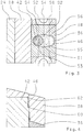
- the Fig. 4 shows the pin 42, which is arranged in the switching shaft 36 and engages in the groove 46 of the hollow shaft 38.
- the pin 42 is designed here in stepped form, whereby two contact points 60, 62 between the pin 42 and the hollow shaft 38 arise. Upon rotation of the pin 42 by the switching shaft 36, this comes first with the contact point 60 with the hollow shaft 38 in contact. Occurs at the contact point 60, for example, a wear, then comes with a rotation of the pin 42 now also the contact point 62 with the hollow shaft 38 in contact.
- an optimized surface pressure between the pin 42 and the hollow shaft 38 can be realized.
Landscapes
- Engineering & Computer Science (AREA)
- General Engineering & Computer Science (AREA)
- Mechanical Engineering (AREA)
- Gear-Shifting Mechanisms (AREA)
Description
- Die Erfindung betrifft eine Schaltvorrichtung mit Servounterstützungseinrichtung nach der im Oberbegriff von Anspruch 1 näher definierten Art.
- Heutige Nutzfahrzeuge, wie Omnibusse und Lastkraftwagen, weisen mit ihrer Frontlenker-Bauweise räumliche Gegebenheiten für den Einbau des Getriebes auf, bei denen das Getriebe zwangsläufig weit vom Fahrersitz wegrückt. Besonders weit wird die Entfernung bei Fahrzeugen mit Unterflur- oder Heckmotoren. Durch das lange, bisweilen stramm laufende Schaltgestänge bei mechanisch geschalteten Getrieben wird der exakte Gangwechsel oft erschwert.
- Es sind pneumatische Schalthilfen in aufgelöster Bauweise bekannt, die aus einem mechanisch-pneumatischen Steuerteil und einem separaten, pneumatischen Kraftteil bestehen. Eine Schalthilfe in aufgelöster Bauweise ist aus Loomann; Zahnradgetriebe; 2. Auflage; Springer Verlag; 1988; S. 225 bekannt. Der Steuerteil ist ein mechanisch betätigtes Steuerventil, das vom Schaltgestänge betätigt wird. Die Übertragung der Wählbewegung beim Gangwechsel geschieht dabei mechanisch direkt auf das Getriebe. Bei der Übertragung der Schaltbewegung wird das Steuerventil betätigt und gleichzeitig die Handschaltkraft mechanisch über einen Hebel auf das Getriebe übertragen. Die Handschaltkraft wird dabei von einem Druckluftzylinder zusätzlich pneumatisch unterstützt. Dieser Druckluftzylinder bildet dabei als ein Zweistellungs-Zylinder mit integriertem hydraulischem Dämpfer den pneumatischen Kraftteil. Eine direkte proportionale Abbildung der Handschaltkraft wird hier nicht erreicht. Die Wege zwischen Steuerteil und Kraftteil sind lang und der Anbau ist platzraubend.
- Die
DE 10 2004 041 543 A1 offenbart eine Schaltvorrichtung mit Servounterstützungseinrichtung für ein Getriebe eines Kraftfahrzeugs, welche eine zentrale Schaltwelle umfasst, deren axiale Verschiebung in einer Wählbewegung und deren Drehbewegung in einer Schaltbewegung resultiert. Bei einer Drehbewegung der zentralen Schaltwelle wird über Stifte zur Übertragung der Handschaltkraft und einen mit den Stiften in Wirkverbindung stehenden Hebel ein Steuerventil der Servounterstützungseinrichtung aktiviert. Die Stifte zur Übertragung der handschaltkraft greifen in Längsnuten im Umfang der Schaltwelle ein und sind derart in den Längsnuten angeordnet, dass eine axiale Verschiebung der Schaltwelle ermöglicht wird. Zur Überbrückung der Servounterstützungseinrichtung in bestimmten Gängen sind an den Längsnuten entsprechende Quernuten vorgesehen. - Aus der
DE 10 2006 006 651 A1 ist eine gattungsgemäße Schaltvorrichtung mit einer Servounterstützungseinrichtung für ein Getriebe eines Fahrzeugs bekannt geworden, welche Mittel zum Schalten und Wählen einer Gangstufe eines Getriebes und eine Steuerstange der Servounterstützungseinrichtung umfasst, auf die eine zu unterstützende Handschaltkraft einwirkt. In der Schaltvorrichtung sind elastische Elemente vorgesehen, um die auf die Servounterstützungseinrichtung einwirkende Handschaltkraft vor der Einleitung in die Servounterstützungseinrichtung zu verändern oder zu begrenzen. - Die
DE 10 2006 006 652 A1 offenbart ebenfalls eine Schaltvorrichtung mit einer Servounterstützungseinrichtung für ein Getriebe eines Fahrzeugs, welche Mittel zum Schalten und Wählen einer Gangstufe eines Getriebes und eine Steuerstange der Servounterstützungseinrichtung umfasst, auf die eine zu unterstützende Handschaltkraft einwirkt. In der Schaltvorrichtung sind Federelemente vorgesehen, um die auf die Servounterstützungseinrichtung einwirkende Handschaltkraft innerhalb der Servounterstützungseinrichtung vor und/oder während der Erzeugung der Servounterstützungskraft zu verändern. - Der vorliegenden Erfindung liegt die Aufgabe zugrunde, eine Ausführungsform einer Schaltvorrichtung mit Servounterstützungseinrichtung darzustellen, mit welcher eine Vorrichtung zur Begrenzung der Servounterstützungskraft optimiert werden kann.
- Die der Erfindung zugrunde liegende Aufgabe wird durch eine, auch die kennzeichnenden Merkmale des Hauptanspruchs aufweisende, gattungsgemäße Schaltvorrichtung mit Servounterstützungseinrichtung gelöst.
- Die erfindungsgemäße Schaltvorrichtung mit Servounterstützungseinrichtung, insbesondere für Getriebe von Nutzfahrzeugen, umfasst ein Schaltgehäuse, Mittel zum Wählen und Schalten einer Gangstufe des Getriebes und eine Übertragungsstelle zur Übertragung der Handschaltkraft auf die Servounterstützungseinrichtung. Die Übertragungsstelle zur Übertragung der Handschaltkraft weist einen Hebel auf, der mit einem Element der Servounterstützungseinrichtung verbunden ist.
- Die Schaltvorrichtung weist erfindungsgemäß eine Vorrichtung zur Begrenzung der Servounterstützungskraft auf, welche unmittelbar neben der Übertragungsstelle zur Übertragung der Handschaltkraft auf die Servounterstützungseinrichtung angeordnet ist und einen in der Schaltwelle angeordneten Stift umfasst, der in mindestens eine Nut einer die Schaltwelle umgebenden Hohlwelle eingreift, wobei durch den in die Nut der Hohlwelle eingreifenden Stift eine Begrenzung der Servounterstützungskraft realisierbar ist. Der Stift ist derart in der Schaltwelle angeordnet, dass eine Bewegung der Schaltwelle eine sofortige Bewegung des Stiftes bewirkt. Vorzugsweise ist der Stift spielfrei bzw. mit nur minimalem Spiel in der Schaltwelle angeordnet. Dabei ist die Nut in der Hohlwelle derart ausgebildet, dass unterschiedliche Verdrehspiele zwischen dem Stift, der in der Schaltwelle angeordnet ist und in die Nut der Hohlwelle eingreift, und der Hohlwelle vorherrschen. Die Verdrehspiele können beispielsweise derart ausgebildet sein, dass für jede Gasse bzw. für jede Gangstufe ein anderes Verdrehspiel vorherrscht, wodurch eine unterschiedliche Begrenzung der Servounterstützungskraft für jede Gasse bzw. für jede Gangstufe realisierbar ist.
- In einer vorteilhaften Ausführungsform der erfindungsgemäßen Schaltvorrichtung sind die Verdrehspiele bei kleineren Gangstufen größer ausgebildet als bei größeren Gangstufen, wodurch für die kleineren Gangstufen eine größere Servounterstützungskraft zu Verfügung gestellt wird, als für die größeren Gangstufen des Getriebes. Ausgehend von beispielsweise der Gangstufe 3 wird hier unter einer kleineren Gangstufe beispielsweise die Gangstufe 2 und unter einer größeren Gangstufe beispielsweise die Gangstufe 4 verstanden.
- In einer weiteren Ausführungsform der erfindungsgemäßen Schaltvorrichtung weist die Hohlwelle im Bereich des Stiftes zur Begrenzung der Servounterstützungskraft eine zweite Nut auf, die in der Hohlwelle um 180 Grad versetzt, also der ersten Nut gegenüberliegend, angeordnet ist. Der Stift zur Begrenzung der Servounterstützungskraft ist hierbei derart ausgebildet und in der Schaltwelle angeordnet, dass er sowohl in die erste als auch in die zweite Nut der Hohlwelle eingreift, wodurch die auftretende Belastung auf die beiden Nuten der Hohlwelle verteilt wird.
- In einer bevorzugten Ausführungsform der erfindungsgemäßen Schaltvorrichtung sind die Kontaktflächen von dem Stift zur Begrenzung der Servounterstützungskraft und der Hohlwelle derart ausgebildet, dass bei einem Kontakt von dem Stift mit der Hohlwelle eine optimierte Flächenpressung erzielbar ist.
- In einer Ausgestaltung sind die Kontaktflächen von Stift und Hohlwelle konisch zueinander ausgebildet. In einer weiteren vorteilhaften Ausgestaltung ist der Stift zur Begrenzung der Servounterstützungskraft im Bereich der Hohlwelle als abgesetzter Stift ausgebildet, wodurch zwei Anlagepunkte zwischen dem Stift und der Hohlwelle entstehen. Es sind auch andere Ausgestaltungen möglich.
- In einer besonders bevorzugten Ausführungsform der erfindungsgemäßen Schaltvorrichtung ist eine axiale Sicherung des Stiftes zur Begrenzung der Servounterstützungskraft entlang seiner Längsachse durch das Schaltgehäuse realisierbar. Es sind auch andere Ausführungsformen möglich, um die axiale Sicherung des Stiftes zu realisieren. Beispielsweise kann der Stift zur Begrenzung der Servounterstützungskraft durch wenigstens einen Sicherungsring und/oder einen Bund am Stift in der Schaltwelle fixiert werden.
- In einer bevorzugten Ausführungsform der erfindungsgemäßen Schaltvorrichtung ist das Element, auf das die zu unterstützende Handschaltkraft wirkt, als Steuerstange der Servounterstützungseinrichtung ausgebildet.
- Durch die erfindungsgemäße Schaltvorrichtung kann somit eine Begrenzung der Servounterstützungskraft durch eine unmittelbar neben der Übertragungsstelle zur Übertragung der Handschaltkraft auf die Servounterstützungseinrichtung angeordnete Vorrichtung zur Begrenzung der Servounterstützungskraft für jede Gangstufe bzw. jede Gasse realisiert werden. Durch die erfindungsgemäße Anordnung kann das Problem von auftretenden Toleranzen entsprechend klein gehalten werden, wodurch die Verdrehspiele zwischen dem Stift, der in der Schaltwelle angeordnet ist und in die Nut der Hohlwelle eingreift, und der Hohlwelle exakt darstellbar sind und somit die Servounterstützungskraft sehr genau auf den gewünschten Wert begrenzt werden kann.
- Im Folgenden wird das Grundprinzip der Erfindung, welche mehrere Ausführungsformen zulässt, an Hand einer Zeichnung beispielhaft näher erläutert.
- Es zeigen:
- Fig. 1
- eine Schaltanlage nach dem Stand der Technik,
- Fig. 2
- eine Schnittdarstellung einer Ausführungsform der erfindungsgemäßen Schaltvorrichtung,
- Fig. 3
- eine Draufsicht der erfindungsgemäßen Schaltvorrichtung und
- Fig. 4
- eine Schnittdarstellung einer Ausführungsform der erfindungsgemäßen Schaltvorrichtung.
- Die
Fig. 1 zeigt in einer Skizze eine Schaltanlage 2 eines Kraftfahrzeuges nach dem Stand der Technik, Von einem Schalthebel 4 aus führt eine Schaltstange 6 über eine Hebelumlenkung 8 zu einer Schaltvorrichtung 11 mit einer pneumatischen Servounterstützungseinrichtung 10. Die pneumatische Servounterstützungseinrichtung 10 weist eine Anschlussleitung 12 auf, die zu einem Vorratsbehälter 14 führt, aus dem die pneumatische Servounterstützungseinrichtung 10 mit Druckluft versorgt wird. Die Hebelumlenkung 8 weist einen ersten Hebel 16 auf, der mit der Schaltstange 6 vorzugsweise gelenkig verbunden ist. Die Hebelumlenkung 8 weist einen zweiten Hebel 18 auf, der wiederum in eine Steuerstange 20 eingreift, die in der pneumatischen Servounterstützungseinrichtung 10 angeordnet ist. Weiterhin ist in der pneumatischen Servounterstützungseinrichtung 10 eine Kolbenstange 22 vorgesehen, in die ein Hebel 24 eingreift, welcher über eine drehbare Schaltwelle 26 mit einem Hebel 28 im Fahrzeuggetriebe 30 verbunden ist. Der Hebel 28 greift in eine Schaltschiene 32 ein, durch die in bekannter Weise Übersetzungsverhältnisse des Getriebes geschaltet werden können. Eine Bewegung des Hebels 24 wird über die Schaltwelle 26 in eine Bewegung des Hebels 28 übertragen, so dass der Hebel 28 die Schaltschiene 32 in eine axiale Bewegung versetzen kann. Bei dieser Bewegung nimmt die Schaltschiene 32 vorzugsweise drei Positionen ein, zwei axiale Endpositionen, die je einem geschalteten Übersetzungsverhältnis entsprechen und eine zwischen den Endpositionen liegende Mittelposition, die einer Neutralstellung des Getriebes entspricht. - Die
Fig. 2 zeigt die erfinderische Schaltvorrichtung 40 in einer Schnittdarstellung. Die Schaltvorrichtung 40 umfasst eine zentrale Schaltwelle 36, welche innerhalb einer Hohlwelle 38 um ihre Achse 58 drehbar gelagert ist. Die Schaltwelle 36 weist an ihrem Umfang in Längsrichtung, also entlang der Achse 58, Längsnuten 50 auf, in die Stifte 34 zur Übertragung der Handschaltkraft eingreifen, die ihrerseits in einem Hebel 18 angeordnet, vorzugsweise in Nadelbüchsen drehbar gelagert sind. Hierbei sind die Stifte 34 derart in den Nuten 50 angeordnet, dass eine axiale Verschiebung der Schaltwelle 36, also die Wählbewegung, ermöglicht wird, wobei ein Verdrehen der Schaltwelle 36 um die Achse 58 zu einem Verschwenken des Hebels 18 führt, was zu einer Aktivierung der Servounterstützungseinrichtung 10 führt, da der Hebel 18 in die hier nicht dargestellte Steuerstange 20 der Servounterstützungseinrichtung 10 eingreift (sieheFig. 1 ). Die von der Servounterstützungseinrichtung 10 erzeugte Servounterstützungskraft wird von der hier nicht gezeigten Kolbenstange 22 auf den Hebel 24 übertragen (sieheFig. 1 ). Der Hebel 24 ist drehfest mit der Hohlwelle 38 verbunden, wodurch die von der Servounterstützungseinrichtung 10 erzeugte Servounterstützungskraft über den Hebel 24 auf die Hohlwelle 38 übertragen wird. Die Hohlwelle 38 ist in der Schaltvorrichtung axial fest angeordnet und mit der Schaltwelle 36 zum Schalten der Schaltschienen 32 verdrehbar angeordnet. - Gemäß der Erfindung weist die Schaltvorrichtung 40 eine Vorrichtung zur Begrenzung der Servounterstützungskraft auf, welche unmittelbar neben der Übertragungsstelle zur Übertragung der Handschaltkraft auf die Servounterstützungseinrichtung 10 angeordnet ist, also unmittelbar neben dem Hebel 18 in dem die Stifte 34 angeordnet sind, welche in die Nuten 50 der Schaltwelle 36 eingreifen. Die Vorrichtung zur Begrenzung der Servounterstützungskraft umfasst einen in der Schaltwelle 36 angeordneten Stift 42, der hier in eine Nut 46 der Hohlwelle 38 eingreift. Die Nut 46 in der Hohlwelle 38 ist hierbei derart ausgebildet, dass zwischen der Nut 46 und dem Stift 42 und somit zwischen der Hohlwelle 38 und der Schaltwelle 36 entsprechende Verdrehspiele vorherrschen. Durch eine entsprechende Ausgestaltung der Nut 46 (siehe
Fig. 3 ) kann für jede Gasse bzw. jede Gangstufe die Servounterstützungskraft entsprechend begrenzt werden. Der in der Schaltwelle 36 angeordnete Stift 42 zur Begrenzung der Servounterstützungskraft ist symmetrisch zu der Nut 50 in der Schaltwelle 36 und somit symmetrisch zu den Stiften 34 zur Übertragung der Handschaltkraft auf die Servounterstützungseinrichtung 10 angeordnet. Eine axiale Sicherung des Stiftes 42 entlang seiner Längsachse ist hier durch das Schaltgehäuse 44 realisiert. - Die Schaltwelle 36 kann drehbar betätigt werden zur Übertragung der Handschaltkraft auf den auslösenden Hebel 18 der Servounterstützungseinrichtung 10 und zur Übertragung der Handschaltkraft auf die Schaltschienen 32 des Getriebes 30. Weiterhin kann die Schaltwelle 36 axial betätigt werden zur Auswahl der zu schaltenden Schaltschiene 32, also für die Wählbewegung.
- Die
Fig. 3 zeigt die Schaltwelle 36, die Hohlwelle 38, welche die Schaltwelle 36 umgibt, die Nut 46 in der Hohlwelle 38, den Stift 42, der in die Nut 46 eingreift und in der Schaltwelle 36 angeordnet ist, den Hebel 24, der drehfest mit der Hohlwelle 38 verbunden ist und den Hebel 18, der über Stifte 34 (sieheFig. 2 ) mit der Schaltwelle 36 in Verbindung steht. Der Stift 42 ist in der Nut 46 in drei verschiedenen Positionen angedeutet, er ist aber in der Nut 46 lediglich einmal vorhanden. Die in derFig. 3 linke Position stellt die Stellung des Stiftes 42 in der Gasse 52 für die Gangstufe 3/4 eines Fahrzeuggetriebes dar. Die mittlere Position stellt die Stellung des Stiftes 42 in der Gasse 54 für die Gangstufe 1/2 dar, während die rechte Position die Stellung des Stiftes 42 in der Gasse 56 für den R-Gang und/oder Crawler-Gang darstellt. Die Nut 46 in der Hohlwelle 38 ist derart ausgebildet, dass unterschiedliche Verdrehspiele s1 - s6 zwischen dem Stift 42 und der Hohlwelle 38 vorherrschen. Die hier dargestellte Nut 46 ist derart ausgebildet, dass in der Gasse 54 ein größeres Verdrehspiel s1, s2 vorherrscht, als in der Gasse 52 (Verdrehspiel s3, s4). Die Servounterstützungskraft wird solange erzeugt, bis das Verdrehspiel s1 - s6 zwischen dem Stift 42 und der Hohlwelle 38 und somit zwischen der Schaltwelle 36 und der Hohlwelle 38 aufgehoben ist. Ist das Verdrehspiel s1 - s6 aufgehoben, dann wird die Handschaltkraft direkt auf die Hohlwelle 38 übertragen und die Steuerstange 20 der Servounterstützungseinrichtung 10 macht relativ zur Kolbenstange 22 der Servounterstützungseinrichtung 10 keinen Weg mehr. Dadurch, dass die Verdrehspiele s1 - s6 bei kleineren Gangstufen größer ausgebildet sind als bei größeren Gangstufen, kann für die kleineren Gangstufen eine größere Servounterstützungskraft zu Verfügung gestellt werden, als für die größeren Gangstufen. Auch für den R-Gang und/oder Crawler-Gang kann die Servounterstützungskraft durch die Verdrehspiele s5, s6 entsprechend begrenzt werden. - Die
Fig. 4 zeigt den Stift 42, welcher in der Schaltwelle 36 angeordnet ist und in die Nut 46 der Hohlwelle 38 eingreift. Der Stift 42 ist hier in abgesetzter Form ausgeführt, wodurch zwei Anlagepunkte 60, 62 zwischen dem Stift 42 und der Hohlwelle 38 entstehen. Bei einer Verdrehung des Stiftes 42 durch die Schaltwelle 36 kommt dieser zuerst mit dem Anlagepunkt 60 mit der Hohlwelle 38 in Kontakt. Tritt am Anlagepunkt 60 beispielsweise ein Verschleiß auf, so kommt bei einer Verdrehung des Stiftes 42 nun auch der Anlagepunkt 62 mit der Hohlwelle 38 in Kontakt. Durch die in derFig. 4 dargestellte Ausführungsform kann eine optimierte Flächenpressung zwischen Stift 42 und Hohlwelle 38 realisiert werden. -
- 2
- Schaltanlage
- 4
- Schalthebel
- 6
- Schaltstange
- 8
- Hebelumlenkung
- 10
- Servounterstützungseinrichtung
- 11
- Schaltvorrichtung
- 12
- Anschlussleitung
- 14
- Vorratsbehälter
- 16
- Hebel
- 18
- Hebel
- 20
- Element, Steuerstange
- 22
- Kolbenstange
- 24
- Hebel
- 26
- Schaltwelle
- 28
- Hebel
- 30
- Fahrzeuggetriebe
- 32
- Schaltschiene
- 34
- Stift
- 36
- Schaltwelle
- 38
- Hohlwelle
- 40
- Schaltvorrichtung
- 42
- Stift
- 44
- Schaltgehäuse
- 46
- Nut in der Hohlwelle
- 50
- Nut in der Schaltwelle
- 52
- Gasse Gangstufe 3/4
- 54
- Gasse Gangstufe 1/2
- 56
- Gasse R-Gang und/oder Crawler-Gang
- 58
- Achse
- 60
- Anlagepunkt
- 62
- Anlagepunkt
Claims (9)
- Schaltvorrichtung (11, 40) mit Servounterstützungseinrichtung (10) für ein Getriebe (30) eines Fahrzeuges, mit einem Schaltgehäuse (44), mit Mittel zum Wählen und Schalten einer Gangstufe des Getriebes (30), mit einer Übertragungsstelle zur Übertragung der Handschaltkraft auf die Servounterstützungseinrichtung (10) und mit Mittel, um die auf die Servounterstützungseinrichtung (10) einwirkende Handschaltkraft zu verändern und/oder zu begrenzen, wobei die Übertragungsstelle der Handschaltkraft einen Hebel (18) aufweist, der mit einem Element (20) der Servounterstützungseinrichtung (10) verbunden ist, dadurch gekennzeichnet, dass die Schaltvorrichtung (11, 40) eine Vorrichtung zur Begrenzung der Servounterstützungskraft aufweist, welche unmittelbar neben dem Hebel (18) der Übertragungsstelle zur Übertragung der Handschaltkraft auf die Servounterstützungseinrichtung (10) angeordnet ist und einen in der Schaltwelle (36) angeordneten Stift (42) umfasst, der in mindestens eine Nut (46) einer die Schaltwelle (36) umgebenden Hohlwelle (38) eingreift, und die Nut (46) in der Hohlwelle (38) derart ausgebildet ist, dass unterschiedliche Verdrehspiele (s1 - s6) zwischen dem Stift (42) und der Hohlwelle (38) vorherrschen.
- Schaltvorrichtung (11, 40) mit Servounterstützungseinrichtung (10) nach Anspruch 1, dadurch gekennzeichnet, dass die Verdrehspiele (s1 - s6) bei kleineren Gangstufen größer ausgebildet sind als bei größeren Gangstufen, wodurch für die kleineren Gangstufen eine größere Servounterstützungskraft zu Verfügung gestellt wird, als für die größeren Gangstufen.
- Schaltvorrichtung (11, 40) mit Servounterstützungseinrichtung (10) nach wenigstens einem der vorangegangenen Ansprüche, dadurch gekennzeichnet, dass die Hohlwelle (38) im Bereich des Stiftes (42) eine zweite Nut aufweist, die der Nut (46) in der Hohlwelle (38) um 180 Grad versetzt angeordnet ist und der Stift (42) derart ausgebildet und in der Schaltwelle (36) angeordnet ist, dass er sowohl in die Nut (46) als auch in die zweite Nut der Hohlwelle (38) eingreift.
- Schaltvorrichtung (11, 40) mit Servounterstützungseinrichtung (10) nach wenigstens einem der vorangegangenen Ansprüche, dadurch gekennzeichnet, dass die Kontaktflächen von Stift (42) und Hohlwelle (38) derart ausgebildet sind, dass bei einem Kontakt eine optimierte Flächenpressung erzielbar ist.
- Schaltvorrichtung (11, 40) mit Servounterstützungseinrichtung (10) nach Anspruch 4, dadurch gekennzeichnet, dass die Kontaktflächen von Stift (42) und Hohlwelle (38) konisch zueinander ausgebildet sind.
- Schaltvorrichtung (11, 40) mit Servounterstützungseinrichtung (10) nach Anspruch 4, dadurch gekennzeichnet, dass der Stift (42) im Bereich der Hohlwelle (38) als abgesetzter Stift ausgebildet ist, wodurch zwei Anlagepunkte (60, 62) zwischen Stift (42) und Hohlwelle (38) entstehen.
- Schaltvorrichtung (11, 40) mit Servounterstützungseinrichtung (10) nach wenigstens einem der vorangegangenen Ansprüche, dadurch gekennzeichnet, dass eine axiale Sicherung des Stiftes (42) entlang seiner Längsachse durch das Schaltgehäuse (44) realisierbar ist.
- Schaltvorrichtung (11, 40) mit Servounterstützungseinrichtung (10) nach wenigstens einem der Ansprüche 1 bis 6, dadurch gekennzeichnet, dass eine axiale Sicherung des Stiftes (42) entlang seiner Längsachse durch wenigstens einen Sicherungsring und/oder einen Bund am Stift (42) realisierbar ist.
- Schaltvorrichtung (11, 40) mit Servounterstützungseinrichtung (10) nach wenigstens einem der vorangegangenen Ansprüche, dadurch gekennzeichnet, dass das Element (20) als Steuerstange der Servounterstützungseinrichtung (10) ausgebildet ist.
Applications Claiming Priority (2)
| Application Number | Priority Date | Filing Date | Title |
|---|---|---|---|
| DE102007048401A DE102007048401A1 (de) | 2007-10-09 | 2007-10-09 | Schaltvorrichtung mit Servounterstützungseinrichtung |
| PCT/EP2008/063124 WO2009047180A1 (de) | 2007-10-09 | 2008-10-01 | Schaltvorrichtung mit servounterstützungseinrichtung |
Publications (2)
| Publication Number | Publication Date |
|---|---|
| EP2195559A1 EP2195559A1 (de) | 2010-06-16 |
| EP2195559B1 true EP2195559B1 (de) | 2017-11-22 |
Family
ID=40227580
Family Applications (1)
| Application Number | Title | Priority Date | Filing Date |
|---|---|---|---|
| EP08804948.1A Not-in-force EP2195559B1 (de) | 2007-10-09 | 2008-10-01 | Schaltvorrichtung mit servounterstützungseinrichtung |
Country Status (7)
| Country | Link |
|---|---|
| EP (1) | EP2195559B1 (de) |
| JP (1) | JP5417333B2 (de) |
| CN (1) | CN101821533B (de) |
| BR (1) | BRPI0818653A2 (de) |
| DE (1) | DE102007048401A1 (de) |
| RU (1) | RU2010118015A (de) |
| WO (1) | WO2009047180A1 (de) |
Families Citing this family (1)
| Publication number | Priority date | Publication date | Assignee | Title |
|---|---|---|---|---|
| CN115182992B (zh) * | 2022-06-20 | 2023-11-07 | 陕西法士特齿轮有限责任公司 | 一种调整变速器挂挡助力结构 |
Family Cites Families (7)
| Publication number | Priority date | Publication date | Assignee | Title |
|---|---|---|---|---|
| DE19539471A1 (de) * | 1995-10-24 | 1997-04-30 | Zahnradfabrik Friedrichshafen | Schaltvorrichtung für Kraftfahrzeug-Wechselgetriebe - Pneumatischer Schaltservo - |
| DE19839850B4 (de) * | 1998-09-02 | 2010-01-28 | Zf Friedrichshafen Ag | Schaltvorrichtung für Kraftfahrzeug-Wechselgetriebe |
| DE19840052A1 (de) * | 1998-09-02 | 2000-03-09 | Zahnradfabrik Friedrichshafen | Schaltvorrichtung für Kraftfahrzeug-Wechselgetriebe |
| DE102004041543A1 (de) | 2004-08-27 | 2006-03-02 | Zf Friedrichshafen Ag | Schaltvorrichtung für das Getriebe eines Kraftfahrzeugs |
| DE102006006652A1 (de) | 2006-02-14 | 2007-08-30 | Zf Friedrichshafen Ag | Schaltvorrichtung für Kraftfahrzeug-Wechselgetriebe |
| DE102006006651A1 (de) | 2006-02-14 | 2007-08-16 | Zf Friedrichshafen Ag | Schaltvorrichtung für Kraftfahrzeug-Wechselgetriebe |
| DE102006042211A1 (de) * | 2006-09-08 | 2008-03-27 | Zf Friedrichshafen Ag | Schaltvorrichtung für Kraftfahrzeug-Wechselgetriebe |
-
2007
- 2007-10-09 DE DE102007048401A patent/DE102007048401A1/de not_active Withdrawn
-
2008
- 2008-10-01 CN CN2008801110529A patent/CN101821533B/zh not_active Expired - Fee Related
- 2008-10-01 JP JP2010528364A patent/JP5417333B2/ja not_active Expired - Fee Related
- 2008-10-01 WO PCT/EP2008/063124 patent/WO2009047180A1/de not_active Ceased
- 2008-10-01 RU RU2010118015/11A patent/RU2010118015A/ru unknown
- 2008-10-01 BR BRPI0818653A patent/BRPI0818653A2/pt not_active IP Right Cessation
- 2008-10-01 EP EP08804948.1A patent/EP2195559B1/de not_active Not-in-force
Also Published As
| Publication number | Publication date |
|---|---|
| EP2195559A1 (de) | 2010-06-16 |
| DE102007048401A1 (de) | 2009-04-16 |
| CN101821533A (zh) | 2010-09-01 |
| BRPI0818653A2 (pt) | 2016-06-21 |
| WO2009047180A1 (de) | 2009-04-16 |
| RU2010118015A (ru) | 2011-11-20 |
| CN101821533B (zh) | 2013-07-24 |
| JP2010540876A (ja) | 2010-12-24 |
| JP5417333B2 (ja) | 2014-02-12 |
Similar Documents
| Publication | Publication Date | Title |
|---|---|---|
| EP2220404B1 (de) | Servounterstützungseinrichtung für kraftfahrzeug-wechselgetriebe | |
| DE19902556B4 (de) | Lenkgetrieb mit redundantem Antrieb | |
| EP2153089B1 (de) | Schaltvorrichtung für kraftfahrzeug-wechselgetriebe | |
| WO2000014437A1 (de) | Schaltvorrichtung für kraftfahrzeug-wechselgetriebe | |
| EP2076695B1 (de) | Servounterstützungseinrichtung für kraftfahrzeug-wechselgetriebe | |
| EP1108167A1 (de) | Schaltvorrichtung für kraftfahrzeug-wechselgetriebe | |
| EP2156059B1 (de) | Servounterstützungseinrichtung | |
| EP1836421B1 (de) | Vorrichtung zur betätigung von schaltgabeln | |
| DE102007052460A1 (de) | Wählhebel einer Betätigungseinrichtung für ein Kraftfahrzeug-Wechselgetriebe | |
| DE102005060933B3 (de) | Wählhebel, insbesondere für ein Kraftfahrzeug | |
| EP2068044B1 (de) | Servounterstützungseinrichtung für Kraftfahrzeug-Wechselgetriebe | |
| EP1291560B1 (de) | Hilfskraftunterstützte Getriebeschaltvorrichtung | |
| EP2059695B1 (de) | Schaltvorrichtung für kraftfahrzeug-wechselgetriebe | |
| EP1630460B1 (de) | Schaltvorrichtung für das Getriebe eines Kraftfahrzeugs | |
| DE10234596B3 (de) | Als Kugelumlauflenkung ausgebildete elektrische Servolenkung eines Kraftfahrzeuges | |
| EP2195559A1 (de) | Schaltvorrichtung mit servounterstützungseinrichtung | |
| EP2222531A1 (de) | Servoventil für eine hydraulische servolenkung | |
| DE10232873A1 (de) | Elektromechanischer Getriebesteller | |
| DE10350938A1 (de) | Elektromechanischer Getriebesteller | |
| DE102004037994A1 (de) | Verbindung zwischen Rastenscheibe und Verbindungsstange bei einer Parksperre für ein Kraftfahrzeug | |
| DE102020109952A1 (de) | Lenk-Bedieneinheit mit kompakt verstaubarem Stellantrieb | |
| EP1058639B1 (de) | Drehschieberventil für hilfskraftlenkungen von kraftfahrzeugen | |
| EP3187753B1 (de) | Schaltwählhebelvorrichtung zum wählen und/oder schalten von gangstufen eines schaltgetriebes eines kraftfahrzeuges | |
| DE102016214707A1 (de) | Gangwahlhebel für ein Fahrzeuggetriebe | |
| WO2001076933A1 (de) | Drehschieberventil für hilfskraftlenkungen von kraftfahrzeugen |
Legal Events
| Date | Code | Title | Description |
|---|---|---|---|
| PUAI | Public reference made under article 153(3) epc to a published international application that has entered the european phase |
Free format text: ORIGINAL CODE: 0009012 |
|
| 17P | Request for examination filed |
Effective date: 20100309 |
|
| AK | Designated contracting states |
Kind code of ref document: A1 Designated state(s): AT BE BG CH CY CZ DE DK EE ES FI FR GB GR HR HU IE IS IT LI LT LU LV MC MT NL NO PL PT RO SE SI SK TR |
|
| AX | Request for extension of the european patent |
Extension state: AL BA MK RS |
|
| DAX | Request for extension of the european patent (deleted) | ||
| 17Q | First examination report despatched |
Effective date: 20130409 |
|
| GRAP | Despatch of communication of intention to grant a patent |
Free format text: ORIGINAL CODE: EPIDOSNIGR1 |
|
| INTG | Intention to grant announced |
Effective date: 20170529 |
|
| GRAS | Grant fee paid |
Free format text: ORIGINAL CODE: EPIDOSNIGR3 |
|
| GRAA | (expected) grant |
Free format text: ORIGINAL CODE: 0009210 |
|
| AK | Designated contracting states |
Kind code of ref document: B1 Designated state(s): AT BE BG CH CY CZ DE DK EE ES FI FR GB GR HR HU IE IS IT LI LT LU LV MC MT NL NO PL PT RO SE SI SK TR |
|
| REG | Reference to a national code |
Ref country code: GB Ref legal event code: FG4D Free format text: NOT ENGLISH |
|
| REG | Reference to a national code |
Ref country code: CH Ref legal event code: EP |
|
| REG | Reference to a national code |
Ref country code: IE Ref legal event code: FG4D Free format text: LANGUAGE OF EP DOCUMENT: GERMAN |
|
| REG | Reference to a national code |
Ref country code: AT Ref legal event code: REF Ref document number: 948718 Country of ref document: AT Kind code of ref document: T Effective date: 20171215 |
|
| REG | Reference to a national code |
Ref country code: DE Ref legal event code: R096 Ref document number: 502008015758 Country of ref document: DE |
|
| REG | Reference to a national code |
Ref country code: NL Ref legal event code: MP Effective date: 20171122 |
|
| REG | Reference to a national code |
Ref country code: LT Ref legal event code: MG4D |
|
| PG25 | Lapsed in a contracting state [announced via postgrant information from national office to epo] |
Ref country code: FI Free format text: LAPSE BECAUSE OF FAILURE TO SUBMIT A TRANSLATION OF THE DESCRIPTION OR TO PAY THE FEE WITHIN THE PRESCRIBED TIME-LIMIT Effective date: 20171122 Ref country code: LT Free format text: LAPSE BECAUSE OF FAILURE TO SUBMIT A TRANSLATION OF THE DESCRIPTION OR TO PAY THE FEE WITHIN THE PRESCRIBED TIME-LIMIT Effective date: 20171122 Ref country code: NL Free format text: LAPSE BECAUSE OF FAILURE TO SUBMIT A TRANSLATION OF THE DESCRIPTION OR TO PAY THE FEE WITHIN THE PRESCRIBED TIME-LIMIT Effective date: 20171122 Ref country code: SE Free format text: LAPSE BECAUSE OF FAILURE TO SUBMIT A TRANSLATION OF THE DESCRIPTION OR TO PAY THE FEE WITHIN THE PRESCRIBED TIME-LIMIT Effective date: 20171122 Ref country code: NO Free format text: LAPSE BECAUSE OF FAILURE TO SUBMIT A TRANSLATION OF THE DESCRIPTION OR TO PAY THE FEE WITHIN THE PRESCRIBED TIME-LIMIT Effective date: 20180222 Ref country code: ES Free format text: LAPSE BECAUSE OF FAILURE TO SUBMIT A TRANSLATION OF THE DESCRIPTION OR TO PAY THE FEE WITHIN THE PRESCRIBED TIME-LIMIT Effective date: 20171122 |
|
| PG25 | Lapsed in a contracting state [announced via postgrant information from national office to epo] |
Ref country code: BG Free format text: LAPSE BECAUSE OF FAILURE TO SUBMIT A TRANSLATION OF THE DESCRIPTION OR TO PAY THE FEE WITHIN THE PRESCRIBED TIME-LIMIT Effective date: 20180222 Ref country code: HR Free format text: LAPSE BECAUSE OF FAILURE TO SUBMIT A TRANSLATION OF THE DESCRIPTION OR TO PAY THE FEE WITHIN THE PRESCRIBED TIME-LIMIT Effective date: 20171122 Ref country code: GR Free format text: LAPSE BECAUSE OF FAILURE TO SUBMIT A TRANSLATION OF THE DESCRIPTION OR TO PAY THE FEE WITHIN THE PRESCRIBED TIME-LIMIT Effective date: 20180223 Ref country code: LV Free format text: LAPSE BECAUSE OF FAILURE TO SUBMIT A TRANSLATION OF THE DESCRIPTION OR TO PAY THE FEE WITHIN THE PRESCRIBED TIME-LIMIT Effective date: 20171122 |
|
| PG25 | Lapsed in a contracting state [announced via postgrant information from national office to epo] |
Ref country code: DK Free format text: LAPSE BECAUSE OF FAILURE TO SUBMIT A TRANSLATION OF THE DESCRIPTION OR TO PAY THE FEE WITHIN THE PRESCRIBED TIME-LIMIT Effective date: 20171122 Ref country code: SK Free format text: LAPSE BECAUSE OF FAILURE TO SUBMIT A TRANSLATION OF THE DESCRIPTION OR TO PAY THE FEE WITHIN THE PRESCRIBED TIME-LIMIT Effective date: 20171122 Ref country code: EE Free format text: LAPSE BECAUSE OF FAILURE TO SUBMIT A TRANSLATION OF THE DESCRIPTION OR TO PAY THE FEE WITHIN THE PRESCRIBED TIME-LIMIT Effective date: 20171122 Ref country code: CY Free format text: LAPSE BECAUSE OF FAILURE TO SUBMIT A TRANSLATION OF THE DESCRIPTION OR TO PAY THE FEE WITHIN THE PRESCRIBED TIME-LIMIT Effective date: 20171122 Ref country code: CZ Free format text: LAPSE BECAUSE OF FAILURE TO SUBMIT A TRANSLATION OF THE DESCRIPTION OR TO PAY THE FEE WITHIN THE PRESCRIBED TIME-LIMIT Effective date: 20171122 |
|
| REG | Reference to a national code |
Ref country code: DE Ref legal event code: R097 Ref document number: 502008015758 Country of ref document: DE |
|
| PG25 | Lapsed in a contracting state [announced via postgrant information from national office to epo] |
Ref country code: IT Free format text: LAPSE BECAUSE OF FAILURE TO SUBMIT A TRANSLATION OF THE DESCRIPTION OR TO PAY THE FEE WITHIN THE PRESCRIBED TIME-LIMIT Effective date: 20171122 Ref country code: PL Free format text: LAPSE BECAUSE OF FAILURE TO SUBMIT A TRANSLATION OF THE DESCRIPTION OR TO PAY THE FEE WITHIN THE PRESCRIBED TIME-LIMIT Effective date: 20171122 Ref country code: RO Free format text: LAPSE BECAUSE OF FAILURE TO SUBMIT A TRANSLATION OF THE DESCRIPTION OR TO PAY THE FEE WITHIN THE PRESCRIBED TIME-LIMIT Effective date: 20171122 |
|
| PG25 | Lapsed in a contracting state [announced via postgrant information from national office to epo] |
Ref country code: MT Free format text: LAPSE BECAUSE OF FAILURE TO SUBMIT A TRANSLATION OF THE DESCRIPTION OR TO PAY THE FEE WITHIN THE PRESCRIBED TIME-LIMIT Effective date: 20171122 |
|
| PLBE | No opposition filed within time limit |
Free format text: ORIGINAL CODE: 0009261 |
|
| STAA | Information on the status of an ep patent application or granted ep patent |
Free format text: STATUS: NO OPPOSITION FILED WITHIN TIME LIMIT |
|
| 26N | No opposition filed |
Effective date: 20180823 |
|
| PG25 | Lapsed in a contracting state [announced via postgrant information from national office to epo] |
Ref country code: SI Free format text: LAPSE BECAUSE OF FAILURE TO SUBMIT A TRANSLATION OF THE DESCRIPTION OR TO PAY THE FEE WITHIN THE PRESCRIBED TIME-LIMIT Effective date: 20171122 |
|
| REG | Reference to a national code |
Ref country code: CH Ref legal event code: PL |
|
| GBPC | Gb: european patent ceased through non-payment of renewal fee |
Effective date: 20181001 |
|
| REG | Reference to a national code |
Ref country code: BE Ref legal event code: MM Effective date: 20181031 |
|
| PG25 | Lapsed in a contracting state [announced via postgrant information from national office to epo] |
Ref country code: MC Free format text: LAPSE BECAUSE OF FAILURE TO SUBMIT A TRANSLATION OF THE DESCRIPTION OR TO PAY THE FEE WITHIN THE PRESCRIBED TIME-LIMIT Effective date: 20171122 Ref country code: LU Free format text: LAPSE BECAUSE OF NON-PAYMENT OF DUE FEES Effective date: 20181001 |
|
| REG | Reference to a national code |
Ref country code: IE Ref legal event code: MM4A |
|
| PG25 | Lapsed in a contracting state [announced via postgrant information from national office to epo] |
Ref country code: CH Free format text: LAPSE BECAUSE OF NON-PAYMENT OF DUE FEES Effective date: 20181031 Ref country code: BE Free format text: LAPSE BECAUSE OF NON-PAYMENT OF DUE FEES Effective date: 20181031 Ref country code: FR Free format text: LAPSE BECAUSE OF NON-PAYMENT OF DUE FEES Effective date: 20181031 Ref country code: LI Free format text: LAPSE BECAUSE OF NON-PAYMENT OF DUE FEES Effective date: 20181031 |
|
| PG25 | Lapsed in a contracting state [announced via postgrant information from national office to epo] |
Ref country code: IE Free format text: LAPSE BECAUSE OF NON-PAYMENT OF DUE FEES Effective date: 20181001 Ref country code: GB Free format text: LAPSE BECAUSE OF NON-PAYMENT OF DUE FEES Effective date: 20181001 |
|
| REG | Reference to a national code |
Ref country code: AT Ref legal event code: MM01 Ref document number: 948718 Country of ref document: AT Kind code of ref document: T Effective date: 20181001 |
|
| PG25 | Lapsed in a contracting state [announced via postgrant information from national office to epo] |
Ref country code: AT Free format text: LAPSE BECAUSE OF NON-PAYMENT OF DUE FEES Effective date: 20181001 |
|
| PG25 | Lapsed in a contracting state [announced via postgrant information from national office to epo] |
Ref country code: TR Free format text: LAPSE BECAUSE OF FAILURE TO SUBMIT A TRANSLATION OF THE DESCRIPTION OR TO PAY THE FEE WITHIN THE PRESCRIBED TIME-LIMIT Effective date: 20171122 |
|
| PG25 | Lapsed in a contracting state [announced via postgrant information from national office to epo] |
Ref country code: PT Free format text: LAPSE BECAUSE OF FAILURE TO SUBMIT A TRANSLATION OF THE DESCRIPTION OR TO PAY THE FEE WITHIN THE PRESCRIBED TIME-LIMIT Effective date: 20171122 |
|
| PG25 | Lapsed in a contracting state [announced via postgrant information from national office to epo] |
Ref country code: HU Free format text: LAPSE BECAUSE OF FAILURE TO SUBMIT A TRANSLATION OF THE DESCRIPTION OR TO PAY THE FEE WITHIN THE PRESCRIBED TIME-LIMIT; INVALID AB INITIO Effective date: 20081001 |
|
| PG25 | Lapsed in a contracting state [announced via postgrant information from national office to epo] |
Ref country code: IS Free format text: LAPSE BECAUSE OF FAILURE TO SUBMIT A TRANSLATION OF THE DESCRIPTION OR TO PAY THE FEE WITHIN THE PRESCRIBED TIME-LIMIT Effective date: 20180322 |
|
| PGFP | Annual fee paid to national office [announced via postgrant information from national office to epo] |
Ref country code: DE Payment date: 20220831 Year of fee payment: 15 |
|
| P01 | Opt-out of the competence of the unified patent court (upc) registered |
Effective date: 20230528 |
|
| REG | Reference to a national code |
Ref country code: DE Ref legal event code: R119 Ref document number: 502008015758 Country of ref document: DE |
|
| PG25 | Lapsed in a contracting state [announced via postgrant information from national office to epo] |
Ref country code: DE Free format text: LAPSE BECAUSE OF NON-PAYMENT OF DUE FEES Effective date: 20240501 |