EP2196253A2 - Membranbehälter - Google Patents
Membranbehälter Download PDFInfo
- Publication number
- EP2196253A2 EP2196253A2 EP09158636A EP09158636A EP2196253A2 EP 2196253 A2 EP2196253 A2 EP 2196253A2 EP 09158636 A EP09158636 A EP 09158636A EP 09158636 A EP09158636 A EP 09158636A EP 2196253 A2 EP2196253 A2 EP 2196253A2
- Authority
- EP
- European Patent Office
- Prior art keywords
- treated fluid
- membrane
- membrane container
- shell
- water separating
- Prior art date
- Legal status (The legal status is an assumption and is not a legal conclusion. Google has not performed a legal analysis and makes no representation as to the accuracy of the status listed.)
- Withdrawn
Links
- 239000012528 membrane Substances 0.000 title claims abstract description 200
- XLYOFNOQVPJJNP-UHFFFAOYSA-N water Substances O XLYOFNOQVPJJNP-UHFFFAOYSA-N 0.000 claims abstract description 103
- 239000012530 fluid Substances 0.000 claims abstract description 72
- 230000018044 dehydration Effects 0.000 claims abstract description 17
- 238000006297 dehydration reaction Methods 0.000 claims abstract description 17
- LFQSCWFLJHTTHZ-UHFFFAOYSA-N Ethanol Chemical compound CCO LFQSCWFLJHTTHZ-UHFFFAOYSA-N 0.000 claims description 30
- 239000007864 aqueous solution Substances 0.000 claims description 17
- QTBSBXVTEAMEQO-UHFFFAOYSA-N Acetic acid Chemical compound CC(O)=O QTBSBXVTEAMEQO-UHFFFAOYSA-N 0.000 claims description 9
- 230000003014 reinforcing effect Effects 0.000 claims description 8
- KFZMGEQAYNKOFK-UHFFFAOYSA-N Isopropanol Chemical compound CC(C)O KFZMGEQAYNKOFK-UHFFFAOYSA-N 0.000 claims description 7
- ZWEHNKRNPOVVGH-UHFFFAOYSA-N 2-Butanone Chemical compound CCC(C)=O ZWEHNKRNPOVVGH-UHFFFAOYSA-N 0.000 claims description 6
- CSCPPACGZOOCGX-UHFFFAOYSA-N Acetone Chemical compound CC(C)=O CSCPPACGZOOCGX-UHFFFAOYSA-N 0.000 claims description 6
- RTZKZFJDLAIYFH-UHFFFAOYSA-N Diethyl ether Chemical compound CCOCC RTZKZFJDLAIYFH-UHFFFAOYSA-N 0.000 claims description 6
- 238000005192 partition Methods 0.000 claims description 5
- LCGLNKUTAGEVQW-UHFFFAOYSA-N Dimethyl ether Chemical compound COC LCGLNKUTAGEVQW-UHFFFAOYSA-N 0.000 claims description 4
- LYCAIKOWRPUZTN-UHFFFAOYSA-N Ethylene glycol Chemical compound OCCO LYCAIKOWRPUZTN-UHFFFAOYSA-N 0.000 claims description 4
- -1 acetaldehyde, ketones Chemical class 0.000 claims description 4
- 238000012544 monitoring process Methods 0.000 claims description 4
- QTBSBXVTEAMEQO-UHFFFAOYSA-M Acetate Chemical compound CC([O-])=O QTBSBXVTEAMEQO-UHFFFAOYSA-M 0.000 claims description 2
- 150000001298 alcohols Chemical class 0.000 claims description 2
- 150000001299 aldehydes Chemical class 0.000 claims description 2
- 150000001735 carboxylic acids Chemical class 0.000 claims description 2
- 150000002148 esters Chemical class 0.000 claims description 2
- 150000002170 ethers Chemical class 0.000 claims description 2
- 125000004494 ethyl ester group Chemical group 0.000 claims description 2
- WGCNASOHLSPBMP-UHFFFAOYSA-N hydroxyacetaldehyde Natural products OCC=O WGCNASOHLSPBMP-UHFFFAOYSA-N 0.000 claims description 2
- BDERNNFJNOPAEC-UHFFFAOYSA-N propan-1-ol Chemical compound CCCO BDERNNFJNOPAEC-UHFFFAOYSA-N 0.000 claims description 2
- 238000000034 method Methods 0.000 description 14
- 230000003247 decreasing effect Effects 0.000 description 10
- 238000009434 installation Methods 0.000 description 10
- 239000007788 liquid Substances 0.000 description 10
- 239000007789 gas Substances 0.000 description 8
- 238000000926 separation method Methods 0.000 description 7
- 241000196324 Embryophyta Species 0.000 description 5
- 238000005373 pervaporation Methods 0.000 description 5
- 239000012071 phase Substances 0.000 description 5
- 230000005855 radiation Effects 0.000 description 5
- OKKJLVBELUTLKV-UHFFFAOYSA-N Methanol Chemical compound OC OKKJLVBELUTLKV-UHFFFAOYSA-N 0.000 description 3
- VYPSYNLAJGMNEJ-UHFFFAOYSA-N Silicium dioxide Chemical compound O=[Si]=O VYPSYNLAJGMNEJ-UHFFFAOYSA-N 0.000 description 3
- 239000007791 liquid phase Substances 0.000 description 3
- 229910021536 Zeolite Inorganic materials 0.000 description 2
- 239000002253 acid Substances 0.000 description 2
- 230000007547 defect Effects 0.000 description 2
- 238000010586 diagram Methods 0.000 description 2
- HNPSIPDUKPIQMN-UHFFFAOYSA-N dioxosilane;oxo(oxoalumanyloxy)alumane Chemical compound O=[Si]=O.O=[Al]O[Al]=O HNPSIPDUKPIQMN-UHFFFAOYSA-N 0.000 description 2
- 230000000694 effects Effects 0.000 description 2
- 230000005611 electricity Effects 0.000 description 2
- 239000000446 fuel Substances 0.000 description 2
- 238000010438 heat treatment Methods 0.000 description 2
- 239000002808 molecular sieve Substances 0.000 description 2
- 238000012856 packing Methods 0.000 description 2
- 239000000047 product Substances 0.000 description 2
- URGAHOPLAPQHLN-UHFFFAOYSA-N sodium aluminosilicate Chemical compound [Na+].[Al+3].[O-][Si]([O-])=O.[O-][Si]([O-])=O URGAHOPLAPQHLN-UHFFFAOYSA-N 0.000 description 2
- 239000000126 substance Substances 0.000 description 2
- 238000009834 vaporization Methods 0.000 description 2
- 230000008016 vaporization Effects 0.000 description 2
- 239000002699 waste material Substances 0.000 description 2
- 239000010457 zeolite Substances 0.000 description 2
- OKTJSMMVPCPJKN-UHFFFAOYSA-N Carbon Chemical compound [C] OKTJSMMVPCPJKN-UHFFFAOYSA-N 0.000 description 1
- 240000008042 Zea mays Species 0.000 description 1
- 235000005824 Zea mays ssp. parviglumis Nutrition 0.000 description 1
- 235000002017 Zea mays subsp mays Nutrition 0.000 description 1
- 230000002159 abnormal effect Effects 0.000 description 1
- 150000007513 acids Chemical class 0.000 description 1
- 230000004913 activation Effects 0.000 description 1
- 238000013459 approach Methods 0.000 description 1
- 238000010533 azeotropic distillation Methods 0.000 description 1
- 229910052799 carbon Inorganic materials 0.000 description 1
- 239000002131 composite material Substances 0.000 description 1
- 238000001816 cooling Methods 0.000 description 1
- 235000005822 corn Nutrition 0.000 description 1
- 239000012043 crude product Substances 0.000 description 1
- 238000001514 detection method Methods 0.000 description 1
- 238000009792 diffusion process Methods 0.000 description 1
- IDGUHHHQCWSQLU-UHFFFAOYSA-N ethanol;hydrate Chemical compound O.CCO IDGUHHHQCWSQLU-UHFFFAOYSA-N 0.000 description 1
- 125000001301 ethoxy group Chemical group [H]C([H])([H])C([H])([H])O* 0.000 description 1
- 239000002803 fossil fuel Substances 0.000 description 1
- 230000005484 gravity Effects 0.000 description 1
- 230000007062 hydrolysis Effects 0.000 description 1
- 238000006460 hydrolysis reaction Methods 0.000 description 1
- 150000002576 ketones Chemical class 0.000 description 1
- 150000002605 large molecules Chemical class 0.000 description 1
- 229920002521 macromolecule Polymers 0.000 description 1
- 238000012423 maintenance Methods 0.000 description 1
- 239000000463 material Substances 0.000 description 1
- 125000000956 methoxy group Chemical group [H]C([H])([H])O* 0.000 description 1
- 239000000203 mixture Substances 0.000 description 1
- 238000005086 pumping Methods 0.000 description 1
- 239000002994 raw material Substances 0.000 description 1
- 230000008929 regeneration Effects 0.000 description 1
- 238000011069 regeneration method Methods 0.000 description 1
- 238000007873 sieving Methods 0.000 description 1
- 239000000741 silica gel Substances 0.000 description 1
- 229910002027 silica gel Inorganic materials 0.000 description 1
- 239000000377 silicon dioxide Substances 0.000 description 1
- 150000003384 small molecules Chemical class 0.000 description 1
- 239000000243 solution Substances 0.000 description 1
Images



Classifications
-
- B—PERFORMING OPERATIONS; TRANSPORTING
- B01—PHYSICAL OR CHEMICAL PROCESSES OR APPARATUS IN GENERAL
- B01D—SEPARATION
- B01D61/00—Processes of separation using semi-permeable membranes, e.g. dialysis, osmosis or ultrafiltration; Apparatus, accessories or auxiliary operations specially adapted therefor
- B01D61/36—Pervaporation; Membrane distillation; Liquid permeation
- B01D61/362—Pervaporation
-
- B—PERFORMING OPERATIONS; TRANSPORTING
- B01—PHYSICAL OR CHEMICAL PROCESSES OR APPARATUS IN GENERAL
- B01D—SEPARATION
- B01D63/00—Apparatus in general for separation processes using semi-permeable membranes
- B01D63/06—Tubular membrane modules
- B01D63/066—Tubular membrane modules with a porous block having membrane coated passages
-
- B—PERFORMING OPERATIONS; TRANSPORTING
- B01—PHYSICAL OR CHEMICAL PROCESSES OR APPARATUS IN GENERAL
- B01D—SEPARATION
- B01D2319/00—Membrane assemblies within one housing
- B01D2319/02—Elements in series
- B01D2319/022—Reject series
-
- C—CHEMISTRY; METALLURGY
- C02—TREATMENT OF WATER, WASTE WATER, SEWAGE, OR SLUDGE
- C02F—TREATMENT OF WATER, WASTE WATER, SEWAGE, OR SLUDGE
- C02F2209/00—Controlling or monitoring parameters in water treatment
- C02F2209/02—Temperature
-
- Y—GENERAL TAGGING OF NEW TECHNOLOGICAL DEVELOPMENTS; GENERAL TAGGING OF CROSS-SECTIONAL TECHNOLOGIES SPANNING OVER SEVERAL SECTIONS OF THE IPC; TECHNICAL SUBJECTS COVERED BY FORMER USPC CROSS-REFERENCE ART COLLECTIONS [XRACs] AND DIGESTS
- Y02—TECHNOLOGIES OR APPLICATIONS FOR MITIGATION OR ADAPTATION AGAINST CLIMATE CHANGE
- Y02E—REDUCTION OF GREENHOUSE GAS [GHG] EMISSIONS, RELATED TO ENERGY GENERATION, TRANSMISSION OR DISTRIBUTION
- Y02E50/00—Technologies for the production of fuel of non-fossil origin
- Y02E50/10—Biofuels, e.g. bio-diesel
Definitions
- the present invention relates to a membrane container containing water separating membranes.
- the present invention relates to a membrane container in which water separating membranes are modularized into a plural number of units to decrease the size of a plant.
- the present invention relates to a membrane container in which the exposed area of the outer surface of the membrane container is decreased to reduce the heat radiation loss.
- ethanol As a fuel source as an alternative fossil fuel, ethanol has attracted attention, and the market size thereof is predicted to be 55 million kiloliters in 2010.
- a crude product obtained from a biological raw material such as corn must be distilled and refined so as to be dehydrated to at least 99.5 wt%.
- dehydrating a dilute ethanol aqueous solution is distilled in a distilling column so as to be concentrated to a point close to the azeotropic point of an ethanol-water system, and then the solution is dehydrated.
- Another method is also available in which a plurality of molecular sieve tanks are arranged, and dehydration is accomplished while these tanks are switched over in batch mode. This method also has a drawback in that the regeneration of the molecular sieve tank consumes large amounts of energy.
- Japanese Unexamined Patent Application Publication No. 58-21629 discloses a technique in which an element that does not have the above-described drawbacks, such as a water separating membrane, is used.
- a dehydrator using the water separating membrane has problems of large size and poor maintainability.
- the present invention was made in view of the above circumstances, and accordingly, an object thereof is to provide a membrane container in which water separating membranes are modularized into a plural number of units to facilitate the increase in size of the water separating membrane and to decrease the scale of a plant equipped with a dehydrator using the water separating membranes. Furthermore, another object of the present invention is to decrease the exposed area of an outer surface of the membrane container and thereby to reduce the heat radiation loss by modularizing the water separating membranes into a plural number of units.
- the present invention provides a membrane container used in a dehydration system for separating water from treated fluid, including a shell part having a permeated fluid outlet and containing a plurality of water separating membranes arranged in parallel with respect to the flow direction of the treated fluid; an upper channel part having a treated fluid inlet and connecting with the upper end of the shell; and a lower channel part having a treated fluid outlet and connecting with the lower end of the shell part.
- a treated fluid inlet is provided in the upper channel part or the lower channel part
- a treated fluid outlet is provided in the upper channel part or the lower channel part.
- the permeated fluid outlet, the treated fluid inlet, and the treated fluid outlet are generally formed as a permeated fluid outlet nozzle, a treated fluid inlet nozzle, and a treated fluid outlet nozzle, respectively.
- the shell part preferably has a reinforcing wall extending in the lengthwise direction thereof.
- the reinforcing wall preferably has at least one through hole.
- the upper and lower channel parts each have an end plate part
- the shell part have an end plate part at positions corresponding to the end plate parts of the upper and lower channel parts
- a partition plate be further provided between the end plate parts of the upper and lower channel parts and the end plate of the shell part.
- the channel part preferably has at least one steam part for applying heat to the treated fluid. Also, a steam part for applying heat to the treated fluid is preferably further provided on the outer surface of the shell pant.
- a temperature measuring device for monitoring the temperature of the treated fluid is preferably provided. Also, a concentration measuring device for monitoring the concentration of the treated fluid is preferably provided.
- the treated fluid is generally an organic aqueous solution.
- the organic component of the organic aqueous solution is preferably one organic component selected from the group consisting of alcohols such as ethanol, propanol, isopropanol, and glycol, carboxylic acids such as acetic acid, ethers such as dimethyl ether and diethyl ether, aldehydes such as acetaldehyde, ketones such as acetone and methyl ethyl ketone, and esters such as ethyl ester acetate, and is preferably water-soluble.
- alcohols such as ethanol, propanol, isopropanol, and glycol
- carboxylic acids such as acetic acid
- ethers such as dimethyl ether and diethyl ether
- aldehydes such as acetaldehyde
- ketones such as acetone and methyl ethyl ketone
- esters such as ethyl ester acetate
- a membrane container in which the above-described configuration is employed, and the water separating membranes are modularized into a unit of plural numbers to facilitate the increase in size of the water separating membrane in a plant equipped with a dehydrator using the water separating membranes.
- a membrane container in which the above-described configuration is employed, and the water separating membranes are modularized into a plural number of units to decrease the size of a plant equipped with a dehydrator using the water separating membranes.
- a membrane container in which the above-described configuration is employed, and the water separating membranes are modularized into a plural number of units to improve the maintainability, for example, for checking airtightness of the membrane container in a plant equipped with a dehydrator using the water separating membranes.
- a membrane container in which the above-described configuration is employed, and the water separating membranes are modularized into a plural number of units to decrease the exposed area of an outer surface of the membrane container, thereby reducing the heat radiation loss.
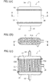
- FIG. 1 (a) is a front view showing one embodiment of a membrane container in accordance with the present invention.
- the membrane container 1 in accordance with the present invention includes a shell part 11, an upper channel part 12, a lower channel part 13, a treated fluid inlet nozzle 14, a treated fluid outlet nozzle 15, and a permeated fluid outlet nozzle 16.
- the shell part 11 is a cylinder having an elliptical cross section, and the upper channel part 12 and the lower channel part 13 are connected to both of the upper and lower ends of the shell part 11 via packings 12a and 13a, respectively.
- the shell part 11 is provided with the permeated fluid outlet nozzle 16, and the upper and lower channel parts 12 and 13 are provided with the treated fluid inlet nozzle 14 and the treated fluid outlet nozzle 15, respectively.
- FIG. 1(b) is a horizontal sectional view, taken along the line A-A of FIG. 1(a) , showing one embodiment of a membrane container in accordance with the present invention.
- FIG. 1(c) is a side sectional view, taken along the line B-B of FIG. 1(b) , showing one embodiment of a membrane container in accordance with the present invention.
- the membrane container 1 in accordance with the present invention can contain several water separating membrane parts 710 arranged in parallel.
- FIG. 1 shows an example in which monolith-type membrane parts are used as the water separating membrane parts 710. However, tubular-type membrane parts may also be used.
- the shell part 11 is a cylinder having an elliptical cross section, and the circle curvature of each end thereof coincides with the circle curvature of the water separating membrane part 710.
- reinforcing walls 17 are arranged in the shell part 11.
- the reinforcing walls 17 can be formed so as to partition individual water separating membrane parts 710.
- the configuration of the reinforcing walls 17 is not limited to this embodiment.
- the reinforcing wall 17 is provided with at least one through hole. Thereby, a fluid flows in the whole of the shell part 11.
- the membrane container 1 in accordance with the present invention can be used in any of a horizontal position, a vertical position, and an inclined position.
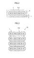
- FIG. 2 is a top view showing the membrane container 1 in accordance with the present invention and the installation space thereof.
- D denotes the installation space for installing the membrane container
- L denotes work space width, piping space width, and measuring space width.
- the plurality of water separating membrane parts have been incorporated in the cylindrical shell, and a plurality of cylindrical shell parts have been installed according to the quantity to be treated. Therefore, the conventional membrane container has a drawback of needing a large installation space.
- the plurality of water separating membrane parts 710 are incorporated in the membrane container 1 according to the quantity to be treated as shown in FIG. 2 . Thereby, the installation space D can be decreased.
- N number of membrane containers is present, and a work space D for installing the membrane container 1 is 0.5 m.
- the work space can be decreased by a factor of 1/(N-1).
- Conventional installation space: N ⁇ D + 0.5 ⁇ 2 ⁇ N ⁇ D + 0.5 ⁇ 2 N ⁇ D + 1 ⁇ 2
- Present invention installation space: N ⁇ D + 0.5 ⁇ 2 ⁇ D + 0.5 ⁇ 2 ND + 1 ⁇ D + 1
- the area of shell outer wall surface is decreased.
- the area of outer wall surface of the membrane container in accordance with the present invention is compared with the area of the conventional outer wall surface.
- Area of conventional outer wall surface ⁇ ⁇ D ⁇ N ⁇ L L : m ⁇ e ⁇ m ⁇ b ⁇ r ⁇ a ⁇ n ⁇ e l ⁇ e ⁇ n ⁇ g ⁇ h ⁇ t
- Area of present invention outer wall surface ⁇ D + N - 1 ⁇ D ⁇ L
- the area of the shell outer wall surface in contact with the atmosphere increases by a factor ofN according to the number N of the water separating membrane parts.
- the membrane container 1 by using the membrane container 1, ( ⁇ 2 - ⁇ )/(N+ ⁇ -1) approaches zero when the number N of the water separating membrane parts is infinite.
- the area of shell outer wall surface can be decreased by a factor of about three as compared with the conventional configuration.
- the water separating membrane used in the present invention separates water by using the pervaporation method in which the supply side is a liquid phase and the permeation side is a gas phase. In this separation method, when the permeating component changes in phase from liquid to gas, the temperature of treated fluid is decreased by latent heat of vaporization.
- the water separating membrane can also be used for the separation in a gas phase or a liquid phase not involving a phase change in a method other than the pervaporation method.
- the permeation rate of water separating membrane is decreased greatly by a decrease in the temperature of treated fluid. Therefore, to keep the temperature of treated fluid constant, a heating means such as a steam heater is necessary.
- the membrane container 1 in accordance with the present invention can reduce the heat radiation loss by decreasing the area of shell outer wall surface. Therefore, by using the membrane container in accordance with the present invention, the decrease in the temperature of treated fluid can be prevented without the use of a heating means.
- FIG. 3 is a top view showing one embodiment of a membrane container unit 30 in which a plurality of membrane containers 1 in accordance with the present invention are arranged in parallel. As shown in FIG. 3 , the several membrane containers 1 are arranged in parallel. Thereby, a proper increase in scale can be achieved easily according to the quantity to be treated.
- the membrane containers 1 may be arranged so that the shell outer wall surface of a membrane container 1 comes into contact with the shell outer wall surface of another membrane container 1. The heat radiation loss can thereby be reduced effectively.
- the steam heater may be arranged in the upper and lower channel parts 12 and 13. Alternatively, the steam heater may be arranged on the side surface of the membrane container 1.
- FIG. 4(a) is a front view of the steam heater provided on the side surface of the membrane container in accordance with the present invention.
- a zigzag-shaped steam heater 41 is arranged on the side surface of the membrane container.
- FIG. 4(b) is a top view of the steam heaters arranged on the side surfaces of the plurality of membrane containers in accordance with the present invention. The zigzag-shaped steam heaters 41 are arranged in the spaces between the membrane containers.
- the steam heaters By arranging the steam heaters appropriately, the decrease in the temperature of treated fluid can be prevented.
- the permeation rate of water separating membrane can be prevented from decreasing.
- One type of common zigzag-shaped steam heater is shown. However, the type of the steam heater is not limited to the above-described zigzag type, and a steam heater of another type can also be used.
- FIG. 5 is a sectional view showing one embodiment of the series-type membrane container in accordance with the present invention.
- the several water separating membrane parts 710 are arranged in parallel in the shell part 11. Therefore, the treated fluid passes through the respective water separating membrane parts 710 at the same time.
- the treated fluid passes through the respective water separating membrane parts 710 one after another.
- the membrane container 5 shown in FIG. 5 contains the several water separating membrane parts 710 in parallel.
- the membrane container 5 includes a shell part 51, an upper channel part 52, a lower channel part 53, a treated fluid inlet nozzle 54, a treated fluid outlet nozzle 55, and a permeated fluid outlet nozzle 56.
- the shell part 51 is a cylinder having an elliptical cross section, and the upper channel part 52 and the lower channel part 53 are connected to both of the upper and lower ends of the shell part 51 via packings 52a and 53a, respectively.
- the shell part 51 is provided with the permeated fluid outlet nozzle 56, and the upper and lower channel part 52 is provided with the treated fluid inlet nozzle 54 and the treated fluid outlet nozzle 55.
- Partition plates 58 are provided in the upper and lower channel parts 52 and 53 in a state of being inserted in end plate parts 58a.
- the treated fluid is caused to pass through the water separating membrane parts 710 one after another by the partition plates 58. Thereby, the flow velocity of treated fluid can be increased, and therefore the movement of substance can be accelerated.
- FIG. 6 is a schematic diagram showing one embodiment of a dehydration system 100 using the membrane containers in accordance with the present invention.
- crude ethanol is assumed as a treated fluid to be dehydrated.
- concentration of the crude ethanol aqueous solution an aqueous solution having an ethanol concentration of 94.5 to 94.8 wt% is assumed. That is to say, crude ethanol containing ethanol as an organic component is used as the treated fluid.
- product fluid obtained finally, that is, product ethanol (dehydrated ethanol) has an ethanol concentration of 99.5 to 99.8 wt%.
- the dehydration system 100 of this embodiment is primarily made up of membrane containers 101 to 110, steam parts 121 to 132, and a cooler 133.
- Each of the membrane containers 101 to 110 has at least one water separating membrane part 710.
- the principle of the dehydration system 100 of this embodiment is the pervaporation method in which the primary side of membrane is a liquid phase, and the secondary side thereof is a gas phase.
- the liquid having permeated the membrane is vaporized by a reduced pressure on the secondary side, and the latent heat of vaporization is supplied by the latent heat of heat from the primary side to the secondary side. Therefore, the inlet temperature of the membrane container 101 is increased by the steam part 131, and intermediate steam heaters 121 to 130 are arranged between the membrane containers 102 to 110, by which the decrease in temperature can be made small. Thereby, the water separation performance of the membrane can be improved.
- the water separation membrane part 710 is a device for separating water from an organic aqueous solution by the pervaporation method.
- the organic aqueous solution is a mixture of water and a liquid soluble in water.
- As the liquid soluble in water ethanol, methanol, isopropyl alcohol, acids such as acetic acid, and ketones such acetone can be cited.
- the liquid soluble in water is not limited to these liquids.
- FIG. 7 (a) is a top view of the monolith-type water separating membrane part 710.
- FIG. 7 (b) is a sectional view of the monolith-type water separating membrane part 710, being a sectional view taken along the line C-C of FIG. 7 (a) .
- the monolith-type water separating membrane part 710 is configured by providing a plurality of flow paths 710c for organic aqueous solution, which are one or more hollow parts extending in the up and down direction to allow the organic aqueous solution to pass through, in a columnar water separating membrane 710d.
- the flow path 710c for organic aqueous solution in the water separating membrane is called the primary side or the supply side of membrane, and the outside of the water separating membrane 710d is called the secondary side or the permeation side.
- the water separating membrane part 710 is preferably provided so that the direction of the flow path is parallel with the vertical direction.
- an organic aqueous solution is supplied from an inlet 710a on the lower side in the vertical direction while the pressure on the permeation side of the water separating membrane part 710 is reduced, being caused to flow in the direction opposite to gravity, and is discharged from an outlet 710b on the upper side in the vertical direction.
- water in the organic aqueous solution is changed to water vapor, and the water vapor is drawn out to the permeation side from the side surface of the columnar water separating membrane 710d.
- the organic aqueous solution recovered from the outlet 710b of the water separating membrane part is dehydrated.
- the monolith-type water separating membrane part 710 shown in FIG. 7 is shown schematically.
- a water separating membrane part provided with thirty holes each having a diameter of 3 mm in a columnar water separating membrane having a diameter of 30 mm can be used.
- a water separating membrane part provided with two hundred holes each having a diameter of 2 mm in a columnar water separating membrane having a diameter of 150 to 200 mm can be used.
- the length of the water separating membrane part can be determined appropriately by one skilled in the art according to the desired membrane performance.
- a water separating membrane part having a length ranging from 150 mm to 1 m can be used.
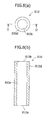
- FIG. 8 (a) is a top view of a tubular-type water separating membrane part 810.
- FIG. 8 (b) is a sectional view, taken along the line D-D of FIG. 8 (a) , of the tubular-type water separating membrane part 810.
- the tubular-type water separating membrane part 810 is a tubular water separating membrane 810d provided with only one flow path 810c for organic aqueous solution therein.
- the tubular-type water separating membrane part 810 has the same installation mode and operation effect as those of the monolith-type water separating membrane part.
- a tubular-type water separating membrane part having an outside diameter of 10 mm and an inside diameter of 7 mm can be used.
- a tubular-type water separating membrane part having an outside diameter of 30 mm and an inside diameter of 22 mm can be used.
- a tubular-type water separating membrane part having a length ranging from 150 mm to 1 m can be used.
- an inorganic porous membrane in which holes on the order of nanometers or smaller are controlled precisely can be used.
- the porous membrane having fine holes achieves a molecule sieving effect of allowing small-molecule gases to pass through and exclude large-molecule gases, and exhibits a behavior of activation diffusion in which the permeation factor thereof increases with the increase in temperature.
- a porous membrane having fine holes a carbon membrane, a silica membrane, and a zeolite membrane can be mentioned.
- a silica- or zeolite-based inorganic water separating membrane having fine holes of 10 Angstroms or less is suitable.
- the inorganic water separating membrane described in Japanese Patent No. 2808479 can also be applied.
- the inorganic water separating membrane described in Japanese Patent No. 2808479 is an acid-resistant composite separation membrane obtained by carrying silica gel obtained through hydrolysis of alkoxysilane containing an ethoxy group or methoxy group in the fine holes of an inorganic porous body.
- the shape, size, and material of the water separating membrane part can be selected appropriately by one skilled in the art according to the intended use.
- all of the membrane containers 101 to 110 may be the same, and some of the membrane containers may be different.
- the membrane containers equipped with the tubular-type water separating membrane parts and the membrane containers equipped with the monolith-type water separating membrane parts can be arranged alternately.
- respective membrane containers can have a different number of water separating membrane parts.
- the cooler 133 may be a cooler capable of cooling a high-temperature organic aqueous solution that has passed through the membrane containers 101 to 110 to an ordinary temperature.
- an ordinary heat exchanger can be used as the cooler 133.
- the dehydration system 100 of this embodiment may be configured so that a detector is installed at the outlet of the membrane container.
- the detector can continuously monitor the state of the membrane container, and can carry out on-line detection of a defect.
- the detector detects a change in temperature and concentration. For example, when the quantity of permeation is decreased by clogging, the detector detects that the decrease in outlet temperature on the primary side is small. Also, when the quantity of permeation is increased by a defect produced in the membrane, the detector can detect that the decrease in temperature on the secondary side is large. Furthermore, the detector can detect that the outlet concentration on the primary side has been changed by means of the quantity of permeation.
- the dehydration system 100 stops the supply of crude ethanol to the membrane containers 101 to 110. Thereby, broken water separating membrane part in the membrane container can be replaced easily.
- the dehydration system 100 of this embodiment can be configured so that a liquid extracting means is provided on the secondary side.
- a TLU trap GP/GT
- the TLV is a mechanical pump in which steam or compressed air is used as an operating gas to send drain or waste liquid under pressure, and carries out the supply control of the operating gas by the switching of supply and exhaust valves due to the movement of a float in a body.
- the TLV is of two types: a GP type exclusively used for sending drain, waste liquid, and the like under pressure, and a GT type incorporating a trap.
- the TLV is a mechanical pump that does not require electricity. Specifically, level control, electricity, and selection are not required at all.
- the TLV is a pump for high-temperature drain without cavitation.
- the TLV has a wide usable range and high capacity. Specifically, the usable range is 0.3 to 10.5 kg/cm 2 , and the capacity is 6650 kg/hour (at the time when the back pressure is 1 kg, and the operating steam pressure is 7 kg). Furthermore, the capacity is 3.0 kg/hour (at the time when the drain amount is 1T/H, the back pressure is 1 kg, and the operating steam pressure is 3.4 kg).
- the TLV can be used as a high-capacity trap because it can be used for an application in which the positive and negative pressures vary. Furthermore, the inlet and outlet pipes and the supply and exhaust pipes need not be separated because maintenance can be performed in the state in which the pipes are installed. Finally, the TLV is highly reliable because it has a unique lever snap-action mechanism.
- FIG. 9 is a graph showing this relationship.
- the flow velocity at the primary side increased by a factor of six, the bulk substance movement was accelerated significantly. This showed that the water separating ability was improved.
Landscapes
- Engineering & Computer Science (AREA)
- Water Supply & Treatment (AREA)
- Chemical & Material Sciences (AREA)
- Chemical Kinetics & Catalysis (AREA)
- Separation Using Semi-Permeable Membranes (AREA)
Applications Claiming Priority (1)
| Application Number | Priority Date | Filing Date | Title |
|---|---|---|---|
| JP2008290783A JP4929269B2 (ja) | 2008-11-13 | 2008-11-13 | 膜容器 |
Publications (2)
| Publication Number | Publication Date |
|---|---|
| EP2196253A2 true EP2196253A2 (de) | 2010-06-16 |
| EP2196253A3 EP2196253A3 (de) | 2014-03-05 |
Family
ID=41647140
Family Applications (1)
| Application Number | Title | Priority Date | Filing Date |
|---|---|---|---|
| EP09158636.2A Withdrawn EP2196253A3 (de) | 2008-11-13 | 2009-04-23 | Membranbehälter |
Country Status (5)
| Country | Link |
|---|---|
| US (1) | US20100116727A1 (de) |
| EP (1) | EP2196253A3 (de) |
| JP (1) | JP4929269B2 (de) |
| BR (1) | BRPI0900960A2 (de) |
| CA (1) | CA2662314C (de) |
Families Citing this family (6)
| Publication number | Priority date | Publication date | Assignee | Title |
|---|---|---|---|---|
| JP5758096B2 (ja) | 2010-09-09 | 2015-08-05 | 三菱重工業株式会社 | 脱水装置 |
| JP5591041B2 (ja) * | 2010-09-17 | 2014-09-17 | 三菱重工業株式会社 | 脱水装置に用いられる膜容器 |
| JP6051830B2 (ja) * | 2012-12-11 | 2016-12-27 | 東亞合成株式会社 | 有機溶剤水溶液からイソプロピルアルコールを回収する方法 |
| WO2016197112A1 (en) * | 2015-06-05 | 2016-12-08 | Advanced Technology Management Group LLC | Passive heat and mass transfer system |
| JP2019532812A (ja) * | 2016-10-28 | 2019-11-14 | セラヘリックス,インコーポレーテッド | フィルター流れ管理のためのシステムおよび方法 |
| CN113816830A (zh) * | 2021-10-12 | 2021-12-21 | 北京石油化工工程有限公司 | 膜分离降低醋酸甲酯加氢反应器中甲醇含量的方法和系统 |
Citations (3)
| Publication number | Priority date | Publication date | Assignee | Title |
|---|---|---|---|---|
| JPS5821629A (ja) | 1981-07-29 | 1983-02-08 | Showa Denko Kk | 無水エタノ−ルの製造方法 |
| JPH02229529A (ja) | 1989-03-01 | 1990-09-12 | Ngk Insulators Ltd | 流体の分離方法、分離装置および分離膜 |
| JP2808479B2 (ja) | 1990-07-02 | 1998-10-08 | 正司 浅枝 | 耐酸性複合分離膜の製造方法 |
Family Cites Families (18)
| Publication number | Priority date | Publication date | Assignee | Title |
|---|---|---|---|---|
| US3728256A (en) * | 1971-06-22 | 1973-04-17 | Abcor Inc | Crossflow capillary dialyzer |
| FR2231421B1 (de) * | 1973-05-30 | 1976-05-07 | Rhone Poulenc Ind | |
| JPS57105205A (en) * | 1980-12-23 | 1982-06-30 | Nitto Electric Ind Co Ltd | Tubular membrane type separating module |
| JPS61167405A (ja) * | 1985-09-07 | 1986-07-29 | Showa Denko Kk | 液体混合物の分離法 |
| US4897191A (en) * | 1988-05-27 | 1990-01-30 | Zenon Environmental Inc. | Tubular membrane module with fluid shear protection |
| DE3905924C2 (de) * | 1989-02-25 | 1997-11-20 | Geesthacht Gkss Forschung | Verfahren zur Trennung und Rückgewinnung von Komponenten von Gemischen mittels Pervaporation |
| JPH04100505A (ja) * | 1990-08-20 | 1992-04-02 | Toto Ltd | セラミックフィルタの製造方法 |
| DE4207614C1 (de) * | 1992-03-10 | 1993-09-23 | Pall Corp., Glen Cove, N.Y., Us | |
| JP3911370B2 (ja) * | 1998-07-24 | 2007-05-09 | 京セラ株式会社 | ガス分離モジュールおよび液体脱気装置 |
| GB9821706D0 (en) * | 1998-10-07 | 1998-12-02 | Bratton Graham J | Membrane structure |
| DE10106722B4 (de) * | 2001-02-14 | 2008-11-06 | Fraunhofer-Gesellschaft zur Förderung der angewandten Forschung e.V. | Spezielles Hohlfaser-Membranmodul für den Einsatz in stark durch fouling beeinträchtigten Prozessen und seine Herstellung |
| US20040079629A1 (en) * | 2002-10-29 | 2004-04-29 | Jim Wu | Distillation and recycling treatment device |
| JP2007160238A (ja) * | 2005-12-14 | 2007-06-28 | National Institute Of Advanced Industrial & Technology | ガス分離膜モジュールおよびガス分離方法 |
| JP4831480B2 (ja) * | 2006-06-21 | 2011-12-07 | 三浦工業株式会社 | 膜濾過システム |
| GB0704797D0 (en) * | 2007-03-13 | 2007-04-18 | Phoenix Ipr Ltd | Membrane structures and their production and use |
| JP4427572B2 (ja) * | 2007-03-15 | 2010-03-10 | 三菱重工業株式会社 | 脱水装置 |
| JP2008221177A (ja) * | 2007-03-15 | 2008-09-25 | Mitsubishi Heavy Ind Ltd | 脱水用膜分離装置 |
| GB0705079D0 (en) * | 2007-03-16 | 2007-04-25 | Phoenix Ipr Ltd | Process and apparatus for treatment of organic solvents |
-
2008
- 2008-11-13 JP JP2008290783A patent/JP4929269B2/ja not_active Expired - Fee Related
-
2009
- 2009-03-25 BR BRPI0900960-4A patent/BRPI0900960A2/pt not_active IP Right Cessation
- 2009-04-09 CA CA2662314A patent/CA2662314C/en not_active Expired - Fee Related
- 2009-04-13 US US12/422,349 patent/US20100116727A1/en not_active Abandoned
- 2009-04-23 EP EP09158636.2A patent/EP2196253A3/de not_active Withdrawn
Patent Citations (3)
| Publication number | Priority date | Publication date | Assignee | Title |
|---|---|---|---|---|
| JPS5821629A (ja) | 1981-07-29 | 1983-02-08 | Showa Denko Kk | 無水エタノ−ルの製造方法 |
| JPH02229529A (ja) | 1989-03-01 | 1990-09-12 | Ngk Insulators Ltd | 流体の分離方法、分離装置および分離膜 |
| JP2808479B2 (ja) | 1990-07-02 | 1998-10-08 | 正司 浅枝 | 耐酸性複合分離膜の製造方法 |
Also Published As
| Publication number | Publication date |
|---|---|
| JP4929269B2 (ja) | 2012-05-09 |
| US20100116727A1 (en) | 2010-05-13 |
| CA2662314C (en) | 2012-08-21 |
| CA2662314A1 (en) | 2010-05-13 |
| EP2196253A3 (de) | 2014-03-05 |
| JP2010115596A (ja) | 2010-05-27 |
| BRPI0900960A2 (pt) | 2010-07-13 |
Similar Documents
| Publication | Publication Date | Title |
|---|---|---|
| US8721890B2 (en) | Dehydrating system and dehydrating method | |
| CA2662314C (en) | Membrane container | |
| US8142662B2 (en) | Dehydrating system and method for control of spare membrane unit | |
| JP5758096B2 (ja) | 脱水装置 | |
| CA2675397C (en) | Dehydrating apparatus, dehydration system, and dehydration method | |
| CA2699729C (en) | Dehydrator comprising multiple membrane separation units having different degrees of vacuum | |
| US20100219128A1 (en) | Dehydration system and dehydration method | |
| EP2226113A1 (de) | Dehydrierungssystem und dehydrierungsverfahren | |
| WO2013021966A1 (ja) | 脱水システム及び脱水方法 | |
| JP5591041B2 (ja) | 脱水装置に用いられる膜容器 | |
| JP5342134B2 (ja) | 脱水方法 | |
| EP2263783B1 (de) | Membran-Dehydrierungssystem | |
| CN103816804B (zh) | 一种原位分离水相中低浓度有机物的方法 | |
| CA2665294C (en) | Dehydrating system | |
| JP4414911B2 (ja) | 円筒型膜モジュール | |
| O'Suilleabhain | Modelling of hydrophilic pervaporation systems |
Legal Events
| Date | Code | Title | Description |
|---|---|---|---|
| PUAI | Public reference made under article 153(3) epc to a published international application that has entered the european phase |
Free format text: ORIGINAL CODE: 0009012 |
|
| AK | Designated contracting states |
Kind code of ref document: A2 Designated state(s): AT BE BG CH CY CZ DE DK EE ES FI FR GB GR HR HU IE IS IT LI LT LU LV MC MK MT NL NO PL PT RO SE SI SK TR |
|
| AX | Request for extension of the european patent |
Extension state: AL BA RS |
|
| 17P | Request for examination filed |
Effective date: 20100623 |
|
| RIC1 | Information provided on ipc code assigned before grant |
Ipc: B01D 63/06 20060101AFI20130918BHEP Ipc: C12P 7/06 20060101ALI20130918BHEP Ipc: C07C 29/76 20060101ALI20130918BHEP |
|
| PUAL | Search report despatched |
Free format text: ORIGINAL CODE: 0009013 |
|
| AK | Designated contracting states |
Kind code of ref document: A3 Designated state(s): AT BE BG CH CY CZ DE DK EE ES FI FR GB GR HR HU IE IS IT LI LT LU LV MC MK MT NL NO PL PT RO SE SI SK TR |
|
| AX | Request for extension of the european patent |
Extension state: AL BA RS |
|
| RIC1 | Information provided on ipc code assigned before grant |
Ipc: C12P 7/06 20060101ALI20140124BHEP Ipc: B01D 63/06 20060101AFI20140124BHEP Ipc: C07C 29/76 20060101ALI20140124BHEP |
|
| STAA | Information on the status of an ep patent application or granted ep patent |
Free format text: STATUS: THE APPLICATION IS DEEMED TO BE WITHDRAWN |
|
| 18D | Application deemed to be withdrawn |
Effective date: 20140906 |